Page is loading ...

November 2022 ACC-SVN237B-EN
SAFETY WARNING
Only qualified personnel should install and service the equipment. The installation, starting up, and servicing of
heating, ventilating, and air-conditioning equipment can be hazardous and requires specific knowledge and training.
Improperly installed, adjusted or altered equipment by an unqualified person could result in death or serious injury.
When working on the equipment, observe all precautions in the literature and on the tags, stickers, and labels that are
attached to the equipment.
Low Ambient Control
Precedent™ Packaged Rooftop Units
6 to 25 Tons
Installation Instructions
Model Number: Used With:
FIALOAM001* 6 to 25 tons T/Y models with Symbio™ controls
FIALOAM002* 6 to 25 tons W/D models with Symbio™ controls

©2022 ACC-SVN237B-EN
Introduction
Read this manual thoroughly before operating or servicing this
unit.
Warnings, Cautions, and Notices
Safety advisories appear throughout this manual as required.
Your personal safety and the proper operation of this machine
depend upon the strict observance of these precautions.
Important Environmental Concerns
Scientific research has shown that certain man-made
chemicals can affect the earth’s naturally occurring
stratospheric ozone layer when released to the atmosphere. In
particular, several of the identified chemicals that may affect
the ozone layer are refrigerants that contain Chlorine, Fluorine
and Carbon (CFCs) and those containing Hydrogen, Chlorine,
Fluorine and Carbon (HCFCs). Not all refrigerants containing
these compounds have the same potential impact to the
environment. Trane advocates the responsible handling of all
refrigerants-including industry replacements for CFCs and
HCFCs such as saturated or unsaturated HFCs and HCFCs.
Important Responsible Refrigerant
Practices
Trane believes that responsible refrigerant practices are
important to the environment, our customers, and the air
conditioning industry. All technicians who handle refrigerants
must be certified according to local rules. For the USA, the
Federal Clean Air Act (Section 608) sets forth the requirements
for handling, reclaiming, recovering and recycling of certain
refrigerants and the equipment that is used in these service
procedures. In addition, some states or municipalities may
have additional requirements that must also be adhered to for
responsible management of refrigerants. Know the applicable
laws and follow them.
The three types of advisories are defined as follows:
WARNING Indicates a potentially hazardous
situation which, if not avoided, could
result in death or serious injury.
CAUTIONsIndicates a potentially hazardous
situation which, if not avoided, could
result in minor or moderate injury. It could
also be used to alert against unsafe
practices.
NOTICE Indicates a situation that could result in
equipment or property-damage only
accidents.
WARNING
Proper Field Wiring and Grounding
Required!
Failure to follow code could result in death or serious
injury. All field wiring MUST be performed by qualified
personnel. Improperly installed and grounded field
wiring poses FIRE and ELECTROCUTION hazards. To
avoid these hazards, you MUST follow requirements for
field wiring installation and grounding as described in
NEC and your local/state/national electrical codes.
WARNING
Personal Protective Equipment (PPE)
Required!
Failure to wear proper PPE for the job being undertaken
could result in death or serious injury. Technicians, in
order to protect themselves from potential electrical,
mechanical, and chemical hazards, MUST follow
precautions in this manual and on the tags, stickers,
and labels, as well as the instructions below:
• Before installing/servicing this unit, technicians
MUST put on all PPE required for the work being
undertaken (Examples; cut resistant gloves/sleeves,
butyl gloves, safety glasses, hard hat/bump cap, fall
protection, electrical PPE and arc flash clothing).
ALWAYS refer to appropriate Safety Data Sheets
(SDS) and OSHA guidelines for proper PPE.
• When working with or around hazardous chemicals,
ALWAYS refer to the appropriate SDS and OSHA/GHS
(Global Harmonized System of Classification and
Labeling of Chemicals) guidelines for information on
allowable personal exposure levels, proper
respiratory protection and handling instructions.
• If there is a risk of energized electrical contact, arc, or
flash, technicians MUST put on all PPE in accordance
with OSHA, NFPA 70E, or other country-specific
requirements for arc flash protection, PRIOR to
servicing the unit. NEVER PERFORM ANY
SWITCHING, DISCONNECTING, OR VOLTAGE
TESTING WITHOUT PROPER ELECTRICAL PPE AND
ARC FLASH CLOTHING. ENSURE ELECTRICAL
METERS AND EQUIPMENT ARE PROPERLY RATED
FOR INTENDED VOLTAGE.

Introduction
ACC-SVN237B-EN 3
Copyright
This document and the information in it are the property of
Trane, and may not be used or reproduced in whole or in part
without written permission. Trane reserves the right to revise
this publication at any time, and to make changes to its content
without obligation to notify any person of such revision or
change.
Trademarks
All trademarks referenced in this document are the trademarks
of their respective owners.
Revision History
• Added FIALOAM002* 6 to 25 tons W/D/G models with
Symbio™ controls.
• Added Valve control harness (FIALOAM002* only) to Parts
List.
• Updated Controller, Temperature Sensor, and Control Box
Wiring information in the Installation chapters.
WARNING
Follow EHS Policies!
Failure to follow instructions below could result in
death or serious injury.
• All Trane personnel must follow the company’s
Environmental, Health and Safety (EHS) policies
when performing work such as hot work, electrical,
fall protection, lockout/tagout, refrigerant handling,
etc. Where local regulations are more stringent than
these policies, those regulations supersede these
policies.
• Non-Trane personnel should always follow local
regulations.

4 ACC-SVN237B-EN
Table of Contents
General Information . . . . . . . . . . . . . . . . . . . . . . . 5
Inspection . . . . . . . . . . . . . . . . . . . . . . . . . . . . . 5
Parts List . . . . . . . . . . . . . . . . . . . . . . . . . . . . . . 5
Installation . . . . . . . . . . . . . . . . . . . . . . . . . . . . . . . 6
General . . . . . . . . . . . . . . . . . . . . . . . . . . . . . . . 6
Controller . . . . . . . . . . . . . . . . . . . . . . . . . . . . . 6
Pressure Transducer . . . . . . . . . . . . . . . . . . . . 6
Controller Settings and Operation . . . . . . . . . . 10
Jumper Position . . . . . . . . . . . . . . . . . . . . . . . 10
Controller Operation . . . . . . . . . . . . . . . . . . . 10
Pressure Setpoint . . . . . . . . . . . . . . . . . . . . . 10
Labels . . . . . . . . . . . . . . . . . . . . . . . . . . . . . . . 10
Close-Up, Fan Inspection, and Restart . . . . 10
Troubleshooting . . . . . . . . . . . . . . . . . . . . . . . . . 11

ACC-SVN237B-EN 5
General Information
This instruction covers installation of the low ambient kit on
Precedent units with 3 phase condenser fan motor(s).
Important: The kit is not designed for use on units with
eFlex™ option (digit 2 = Z).
Inspection
1. Unpack all components of the kit.
2. Check carefully for shipping damage. If any damage is
found, report it immediately, and file a claim against the
transportation company.
3. Visually inspect the components for shipping damage as
soon as possible after delivery, before it is stored.
Concealed damage must be reported within 15 days.
4. If concealed damage is discovered, stop unpacking the
shipment.
5. Do not remove damaged material from the receiving
location. Take photos of the damage, if possible. The
owner must provide reasonable evidence that the damage
did not occur after delivery.
6. Notify the carrier’s terminal of damage immediately by
phone and by mail. Request an immediate joint inspection
of the damage by the carrier and the consignee.
Note: Do not attempt to repair any damaged parts until the
parts are inspected by the carrier’s representative.
Parts List
Table 1. Parts list
Quantity Description
1 Low Ambient Control Module
1 Control mounting bracket
2 8-32 x 1 in. Screws
2 10-16 x 0.5 in. Screws
1 Temperature Sensor
1 Pressure Transducer
1 Pressure Tap Tee
1 Rubber grommet
1 Outdoor Motor power harness
1 Control power harness
1 Temperature Sensor harness
1 Temperature Sensor extension harness
1 Schematic
1 Installation Guide
1 Installed Accessory Label
1 Valve control harness (FIALOAM002* only)

6 ACC-SVN237B-EN
Installation
General
Controller
1. Disconnect all power from the unit.
2. Remove the compressor and control box access panel(s).
3. Use eight 32 x 1-inch screws to mount the controller
bracket. See Figure 1 for orientation.
4. Open the left-side, low voltage door to access the high
voltage section This is where the controller/bracket will be
mounted. See Figure 1 for mounting location.
5. Use 10-16 x 0.5” screws to mount the assembly to the
control box back panel.
Note: The right side of the assembly will slide into the slot
in the back panel. Secure the left side with screws
(supplied in the kit).
Pressure Transducer
1. Install the supplied Tee on the high pressure service port.
See Figure 2
a. Remove cap nut from high pressure service port.
b. Install the pressure sensor on one of the Tee ports. See
Figure 3.
c. Place the tee flare nut with the valve core depressor on
the high pressure tap. See Figure 4.
d. Tighten flare nut securely to the high pressure service
port and check for leaks.
e. Place cap nut on open port tee.
f. Route wires along with existing sensor wires into main
control box. Refer to wire harness installation section
for proper wire routing path back to controller mounting
location.
g. Connect wires to the appropriate controller terminals.
See schematic.
Table 2. Low ambient controller ratings
Volts, AC 208, 240, 380, 415, 480, 600
Control Voltage 18-30 Vac
Frequency 50-60 Hz
Operating Temperature -40ºF + 140ºF (-40ºC to 60ºC)
Full Load Amps 10 Amps
Transducer Pressure Control Range 0-500 psi
WARNING
Hazardous Voltage w/Capacitors!
Failure to disconnect power and discharge capacitors
before servicing could result in death or serious injury.
Disconnect all electric power, including remote
disconnects and discharge all motor start/run
capacitors before servicing. Follow proper lockout/
tagout procedures to ensure the power cannot be
inadvertently energized. Verify with a CAT III or IV
voltmeter rated per NFPA 70E that all capacitors have
discharged.
Figure 1. Mounting location
Figure 2. High pressure service port
Figure 3. Transducer to tee
High Pressure
Service Port

Installation
ACC-SVN237B-EN 7
Temperature Sensor Installation
The existing thermistor, used by the unit controls, measures
the outdoor ambient air temperature.
• 6 to 12.5 tons - existing thermistor is mounted on the
condenser base pan in front of the second compressor.
• 15 to 25 tons - existing thermistor is mounted in the lower,
right corner of the main control box.
The low ambient controller requires a second thermistor. Both
locations are factory designed with a second hole for the
controller temperature sensor.
1. Install grommet in second hole located next to existing
temperature.
2. Insert controller temperature sensor in grommet. Confirm
majority of the sensor is pushed through the grommet.
Figure 4. Tee and transducer installed on high
pressure service port
WARNING
Hazardous Voltage w/Capacitors!
Failure to disconnect power and discharge capacitors
before servicing could result in death or serious injury.
Disconnect all electric power, including remote
disconnects and discharge all motor start/run
capacitors before servicing. Follow proper lockout/
tagout procedures to ensure the power cannot be
inadvertently energized. Verify with a CAT III or IV
voltmeter rated per NFPA 70E that all capacitors have
discharged.

Installation
8 ACC-SVN237B-EN
Control Box Wiring
1. Disconnect ODM1 from power circuit.
a. Unplug PPM79 (orange connector) from underneath
control box.
b. Remove PPF79 from sheet metal opening in control
box wrapper.
2. Install outdoor motor harness in control box as shown in
Figure 6.
a. Plug PPM79 from OFC1 into PPM79B of the power
harness.
b. Snap PPF79B back into the control box wrapper where
PPF79 was originally placed.
c. Refer to schematic for connection points and install
remaining strip lead connections into controller.
3. Install control power harness in control box as shown in
Figure 7.
a. Refer to schematic and install wires to appropriate
terminals on the controller.
b. Route harness across back panel and up onto right low
voltage door to the adapter board.
Note: Following existing wiring paths to adapter board
but routing through horseshoe shaped opening on
low voltage door.
c. Connect P6 from control power harness to AB-J6.
Refer to main unit schematic sheet 4.
d. For heat pump units, install the valve control harness
included in the kit. See figure 9 for connections. Valve
control harness will be routed with control harness.
4. Temperature sensor harness
a. Install temperature sensor harness in control box as
shown in Figure 8.
b. Refer to schematic and connect wires to appropriate
terminals on the controller.
c. Route harness across back panel and into lower right
corner.
– 6 to 12.5 tons - use temperature sensor extension
harness to continue routing down to sensor location.
– 15 to 25 tons - connect to sensor previously mounted in
control box.
d. Connect harness to temperature sensor connector.
5. Final wiring
a. All harnesses in this kit can utilize the factory installed
releasable wire ties in all routing paths.
b. Secure installed wires with wire ties.
WARNING
Hazardous Voltage w/Capacitors!
Failure to disconnect power and discharge capacitors
before servicing could result in death or serious injury.
Disconnect all electric power, including remote
disconnects and discharge all motor start/run
capacitors before servicing. Follow proper lockout/
tagout procedures to ensure the power cannot be
inadvertently energized. Verify with a CAT III or IV
voltmeter rated per NFPA 70E that all capacitors have
discharged.
Figure 5. Panel mount connector location
Figure 6. Outdoor motor power harness
Figure 7. Control power harness
Figure 8. Temperature sensor harness

Installation
ACC-SVN237B-EN 9
c
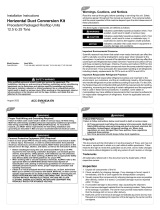
Figure 9. Low ambient controller
REF DES DESCRIPTION LINE NO
LAT LOW AMBIENT TEMP SENSOR 38
LOAM LOW AMBIENT MODULE 24
ODM1 OUTDOOR FAN MOTOR 19
OFC1 OUTDOOR FAN CONTACTOR 18
SOV1 SOLENOID VALVE 40
SYMBIO SYMBIO 700 UC 41
XDCR1 PRESSURE TRANSDUCER CKT1 35
N.C.
PPM127PPM79
37B(BR) 37B(BR)
38B(O) 38B(O)
39B(Y) 39B(Y)
40B(G/Y) 40B(G/Y)
PPF79B
PPM79B
149A(BR)
149A(BR)
150A(O)
150A(O)
151A(Y)
151A(Y)
146A(BR)
146A(BR)
147A(O)
147A(O)
148A(Y)
148A(Y)
37A(BR)
38A(O)
39A(Y)
L1
L2
L3T3
T2
T1
AB-P6
(GY)
(GY)
(BL)
(BL)
(BK)
(BK)
(R)
(R)
(BL/O)
(BL/O)
PPF127
(BR) (BR)
(BR)
(BR)(BR)
J11
P11 J11
PPM11
(BK) (BK)
(R) (R)
PPM16
PPF16
(BK)
(R)
(BK)
(BK)
LOAM
T AMBIENT
C
Y1
Y2
REV VALVE
P1 & P2 BLK
P1 & P2 RED
P1 B.W.G.
P2 B.W.G.
LINE 1
LOAD 1
LINE 2
LOAD 2
LINE 3
LOAD 3
N.O.
HEAT
PUMP
XDCR1
LAT
ODM1
1
2
3
4
1
2
3
4
1
2
3
4
PPF79
1
2
3
4
1
2
3
4
OFC1
1
2
1
2
3
4
1
2
1
2
LOW AMBIENT CONTROLLER
1
2
3
4
SWITCHOVER VALVE 1 OUT
SYMBIO 700 UC
COMMON
COMMON
SWITCHOVER VALVE 2 OUT
1
2
3
4
1
2
3
4
1
2
3
4
1
2
1
2
SOV1
12.5-25T ONLY
6-10T ONLY
WIRE COLOR ABBREVIATION CODES
CODE COLOR COLORCODE
BK BLACK PINKPK
BL BLUE REDR
BR BROWN TURQUOISETQ
G GREEN PURPLEV,(PR)
GY GREY WHITEW
O ORANGE YELLOWY

10 ACC-SVN237B-EN
Controller Settings and Operation
Jumper Position
• For non-heat pump applications, the heat pump select
jumper must be in the default (N.O.) position, and the
REV. VALVE terminal must not be connected.
• For heat pump applications, move the jumper to the (N.C.)
position and wire the REV. VALVE terminal with the REV
Valve harness included in the kit.
Controller Operation
• The LOAM controller is used to maintain head pressure
within an acceptable range when ambient temperature
falls below 50ºF. It reads discharge pressures from both
refrigeration circuits.
• It cycles both outdoor fan motors on and off to maintain the
highest of the two discharge pressures at the selected
setpoint anytime one or more compressors are operating.
Above 50ºF, both fans will be energized continuously.
Pressure Setpoint
Set the pressure setpoint to the recommended value of 245
psig (see Figure 11, p. 10).
At ambient temperatures lower than 50ºF, the controller will
maintain the highest of the two circuits discharge pressures
between 15 psig above and 15 psig below dialed pressure
setpoint.
Labels
Apply self-adhesive labels supplied with the kit to the inside of
the panel covering the main control box:
1. Accessory label: Apply near the unit nameplate.
2. Supplementary wiring diagram label: Schematic can be
placed in schematic pouch already located on back of right
side low voltage door that contains all main unit
schematics.
Close-Up, Fan Inspection, and
Restart
1. Inspect condenser fans:
a. Manually rotate the condenser fans to ensure free
movement and check motor bearings for wear.
b. Verify that all fan mounting hardware and fan hubs are
tight.
2. Connect all power to the unit.
Figure 10. Jumper position
N.O.
Figure 11. Pressure setpoint

ACC-SVN237B-EN 11
Troubleshooting
Confirm the unit is operating properly through the desired
pressure range.
Table 3. Troubleshooting guide
Problem Possible Cause Possible Solution
No fan operation
No 24 volt control voltage Check for 24 Vac at control and verify correct wiring. If wired correctly, check voltage across the
transformer.
No line voltage Check voltage across the brown, orange, and yellow OD motor leads. If no line voltage is
present, verify all wiring is correct.
Improper fan operation
Heat pump jumper not configured
correctly
Refer to the IOM or correct hook-up diagram and verify the heat pump jumper is configured
correctly.
Control is not wired correctly See wiring diagrams. Ensure that the 24 Vac power supply is connected in-phase with the motor
power supply.
No fan modulation
No need to modulate the fan If pressure is equal to or greater than the head pressure control setpoint, the fan will be
operating at full speed.
No input pressure to control Check for proper transducer and Tee installation. Schrader valve depressor must depress
Schrader valve enough to allow refrigerant into pressure transducer.
Miswired Check that the 24Vac signal and the transducer are wired up correctly into the controller.
Erratic fan operation
Control is not wired correctly See wiring diagrams.
Pressure transducer problem Check for proper transducer and Tee installation. Schrader valve depressor must depress
Schrader valve enough to allow refrigerant into pressure transducer.
Dirty or blocked condenser coil Clean condenser coil.
Fan motor is cycling on thermal
overload Dirty or blocked condenser coil Clean condenser coil.
Unit fails to start
Incorrect/No voltage present
Using an AC voltmeter, measure the voltage between the 24 Vac terminals. It should read
approximately 24 volts. Measure line voltage between LINE1, LINE2 and LINE 3 to confirm that
line voltage is present.
Transducer malfunction or not
installed
If lights are flashing alternatively, then no probe is connected or the probe is malfunctioning.
When using a pressure transducer, with power applied to the control, use a voltmeter to
measure volts DC between COMM and P1 or P2, where the wire is connected. The reading
should be according to Table 4 below.
The fuse is blown and/or signs of
damage on the unit Miswired The unit has been mis-wired and may be permanently damaged
Table 4. Pressure vs. voltage
Pressure (psig) Voltage (Vdc)
00.5
50 0.9
100 1.3
150 1.7
200 2.1
250 2.5
300 2.9
350 3.3
400 3.7
450 4.1
500 4.5

©2022
Trane and American Standard have a policy of continuous product and product data improvement and reserve the right to change design and
specifications without notice. We are committed to using environmentally conscious print practices.
Trane and American Standard create comfortable, energy efficient indoor environments for commercial and
residential applications. For more information, please visit trane.com or americanstandardair.com.
ACC-SVN237B-EN 12 Nov 2022
Supersedes ACC-SVN237A-EN (Aug 2022)
/