INSTRUCTIONS
HIGH BAY RAIL® INSTALLATION
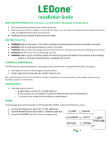
WIRING
the Test Button (Fig. 9)
Connect UNSWITCHED HOT HOT AC
UNSWITCHED circuit, connect UNSWITCHED and
SWITCHED lines together.
SWITCHED circuit, connect SWITCHED HOT
lead to the external.
(V-) DIM lead.
5. DIMDIM
GROUND
connect the BATTERY.
CHARGING
INDICATOR LIGHT
charging.
9. Once the BATTERY
Test Button as
illuminated indicating that the BATTERY
(internal battery)
illumination.
automatically returns to charging mode.
RAIL - IN - 0722 RAB WARRANTY: RAB’s warranty is subject to all terms and conditions found at rablighting.com/warranty
Easy Answers
rablighting.com
Visit our website for product info
Tech Help Line
Call our experts: 888 722-1000
e-mail
Free Lighting Layouts
Answered online or by request
© 2022 RAB LIGHTING Inc.
P-100119
CAUTION: FOR BATTERY BACKUP FIXTURE.
in BATTERY.
BATTERY
(Fig. 8).
NOTE:
UNSWITCHED AC
CAUTION:
FIG. 9
LIGHT
FIXTURE
INSIDE FIXTURE
BATTERY
Pink (or Gray)/DIM–
Black/Switched Line
Green/Ground
White/Neutral
Black/Unswitched Line
Purple/DIM+
BACKUP
DRIVER
BATTERY
CONNECTOR:
CONNECT
ONLY AFTER
AC SUPPLY
POWER IS
CONNECTED
Test Button