13
EN
ATYSg - 541998D - SOCOMEC
CORPORATE HQ CONTACT: SOCOMEC SAS 1-4 RUE DE WESTHOUSE - 67235 BENFELD, FRANCE - WWW.SOCOMEC.COMCORPORATE HQ CONTACT: SOCOMEC SAS 1-4 RUE DE WESTHOUSE - 67235 BENFELD, FRANCE - WWW.SOCOMEC.COM
POWER
AUT
Ø 4 ... 8mm
PROG
OK
AUT
READY
TEST ON LOAD
TEST OFF LOAD
ATyS g
Un
Auto Conf
5
1
10
14
5
1
10
13
0
1
5
10
20
60
0
1
5
10
20
60
G:
H:
E:
F:
REMOTE CONTROL
A: 3 Ph
B: 1 Ph
C: Neutral
D: Neutral
ATyS
Un
N°
PP / PN
1: 220 / 127
2: 380 / 220
3: 400 / 230
4: 415 / 240
5: 480 / 277
6: 208 / 120
7: 220 / 127
8: 230 / 132
9: 240 / 138
10: 380 / 220
11: 400 / 230
12: 415 / 240
13: 480 / 277
5
6
7
8
9
10
11
12
13
14
15
16
18
20
1:
2:
3:
4:
5:
6:
7:
8:
9:
10:
11:
12:
13:
14:
3
3
4
4
5
5
6
6
7
7
8
8
9
10
N°: Δ
U ΔF %
XXX
50 Hz60 Hz
XXXXXXXX
Motorised Changeover Switch
1600A Ref : 95054160
AUT
90°
90°
I II
0
125 A 160 A 200 A 250 A
3 P 4 P 3 P 4 P 3 P 4 P 3 P 4 P
in mm in mm in mm in mm in mm in mm in mm in mm
C
9.61 244 9.61 244 9.61 244 9.61 244 9.61 244 9.61 244 9.61 244 9.61 244
CA
0.39 10 0.39 10 0.39 10 0.39 10 0.39 10 0.39 10 0.59 15 0.59 15
F
11.28 286,5 12.48 317 11.28 286,5 12.48 317 11.28 286,5 12.48 317 12.91 328 14.88 378
M
4.72 120 5.91 150 4.72 120 5.91 150 4.72 120 5.91 150 6.30 160 8.27 210
T
1.42 36 1.42 36 1.42 36 1.42 36 1.42 36 1.42 36 1.97 50 1.97 50
U
0.79 20 0.79 20 0.79 20 0.79 20 0.79 20 0.79 20 0.98 25 0.98 25
W
0.35 9 0.35 9 0.35 9 0.35 9 0.35 9 0.35 9 0.43 11 0.43 11
X
1.10 28 0.87 22 1.10 28 0.87 22 1.10 28 0.87 22 1.30 33 1.30 33
315 A 400 A 500 A 630 A
3 P 4 P 3 P 4 P 3 P 4 P 3 P 4 P
in mm in mm in mm in mm in mm in mm in mm in mm
C
9.61 244 9.61 244 9.61 244 9.61 244 12.64 321 12.64 321 12.64 321 12.64 321
CA
0.59 15 0.59 15 0.59 15 0.59 15 0.59 15 0.59 15 0.79 20 0.79 20
F
12.91 328 14.88 378 12.91 328 14.88 378 14.84 377 17.20 437 14.84 377 17.20 437
M
6.30 160 8.27 210 6.30 160 8.27 210 8.27 210 10.63 270 8.27 210 10.63 270
T
1.97 50 1.97 50 1.97 50 1.97 50 2.56 65 2.56 65 2.56 65 2.56 65
U
1.38 35 1.38 35 1.38 35 1.38 35 1.26 32 1.26 32 1.77 45 1.77 45
W
0.43 11 0.43 11 0.43 11 0.43 11 0.55 14 0.55 14 0.51 13 0.51 13
X
1.30 33 1.30 33 1.30 33 1.30 33 1.67 42,5 1.48 37,5 1.67 42,5 1.48 37,5
3x
Ø 4-8 mm
W
U
CA
5.43
138
6.50
165
X T
Fix. M
F
C
Fix. 7.38
187,5
0.83
21
9.04
229,5
0.49
12,5
0.30
7,5
0.34
8,6
0.64
16,2
0.64
16,2
0.34
8,6
2324
25
26
7
6
2
1
3
4
17
21
22
18
19
16
20
10 118 9 1412 1513
5
Non contractual document.
Subject to change without notice.
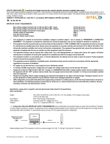
1. MANUAL Mode LED indication.
(Yellow steady light when in Manual Mode).
2. AUTO Mode LED indication
Green steady light when in Auto mode with
no timers running.
Green flashing light when in Auto with timers
running in the background.
3. REMOTE CONTROL Mode LED indication.
Yellow steady light when in remote control
mode.
Remote control mode is achieved with the
Auto/Manu selector switched to Auto and
terminals 312 closed with terminal 317.
Remote control orders are received through
closing 314 to 316 with 317.
4. TEST ON LOAD CONTROL Mode LED
indication. (Yellow steady light when in
TON mode)
5. TEST OFF LOAD CONTROL Mode LED
indication. (Yellow steady light when in
TOF mode).
6. Switch 1 LED position indication.
(Green when in position 1).
7. Source supply I availability LED indication.
(Green when supply I voltage is within the
set limits).
8. Zero position LED indication.
(Yellow when in position 0).
9. Switch 2 LED position indication.
(Green when in position 2).
10. Source supply II availability LED indication.
(Green when supply II voltage is within the
set limits).
11. Sealing screw location 1 for use with
sealing cover (Available as an accessory)
12. Potentiometer 1 : Network Configuration.
(Auto Configuration or refer to the
configuration guide sticker on the front
of the ATyS g when using the predefined
setting positions 1 to 13).
13. Potentiometer 2 : Voltage and Frequency
threshold settings. (Refer to the
configuration guide sticker on the front
of the ATyS g to set the V / Hz threshold.
Positions 1 to 14).
14. Potentiometer 3: Supply FAILURE Time (FT)
Adjustable from 0 to 60 seconds.
15. Potentiometer 4: Supply RETURN Time (RT)
Adjustable from 0 to 60 minutes.
16. READY LED indication
Green steady light : Product in AUTO,
Watchdog OK, Product Available to
changeover.
Green flashing: Settings displayed not
saved or have been changed since last
saved.
(Press PROG OK button in manual mode to
save or revert to last saved settings).
17. Sealing screw location 2 for use with the
sealing cover.
18. FAULT LED indication. (Red steady light in
case of an ATS controller internal fault).
19. Configuration dip switches :
(4 dip switches with 2 positions in each
A to H).
20. PROG OK: Configuration save push button.
(ATTN: Active in Manual Mode ONLY).
Press briefly to confirm and save all set
configuration settings.
Hold pressed for 2 seconds to set the
network supply voltage and frequency by
Auto Configuration.
This is to be followed by pressing briefly to
save the set value configured.
21. Green LED Indication: Power
22. Red LED Indication: Product Unavailable /
Manual Mode / Fault Condition
23. Auto / Manual mode selector switch
(Key version available as an option)
24. Padlocking facility
(Up to 3 padlocks of dia. 4 – 8mm)
25. Emergency manual operation shaft location
(Accessible only in manual mode)
26. Switch position indication window:
I (On switch I) O (Off) II (On switch II).
AUT Mode (RemoteControl)
Imp. ≥60ms maintened
order I
position I
order 0
position 0
order II
position II
Contactor logicImpulse logic
STEP 7B
To enable control, close contact 312 with 317. For
contactor logic bridge contact 316 with 317. To operate:
close the contact corresponding to the desired position.
To force the product to 0 position “OFF” bridge contact
313 with 317.
Dimensions in./mm.
Manual Operation
POWER
AUT
Ø 4 ... 8mm
PROG
OK
AUT
READY
TEST ON LOAD
TEST OFF LOAD
ATyS g
Un
Auto Conf
5
1
10
14
5
1
10
13
0
1
5
10
20
60
0
1
5
10
20
60
G:
H:
E:
F:
REMOTE CONTROL
A: 3 Ph
B: 1 Ph
C: Neutral
D: Neutral
ATyS
Un
N°
PP / PN
1: 220 / 127
2: 380 / 220
3: 400 / 230
4: 415 / 240
5: 480 / 277
6: 208 / 120
7: 220 / 127
8: 230 / 132
9: 240 / 138
10: 380 / 220
11: 400 / 230
12: 415 / 240
13: 480 / 277
5
6
7
8
9
10
11
12
13
14
15
16
18
20
1:
2:
3:
4:
5:
6:
7:
8:
9:
10:
11:
12:
13:
14:
3
3
4
4
5
5
6
6
7
7
8
8
9
10
N°: Δ
U ΔF %
XXX
50 Hz60 Hz
XXXXXXXX
Motorised Changeover Switch
1600A Ref : 95054160
STEP 7C
AUT Mode (AutomaticControl)
STEP 7A
Ensure that the emergency handle is not
inserted in the product and turn the mode
selector to the AUT position.
LED “Power” Green: ON
LED Manuel/Default: OFF
Padlocking Mode
(as standard : in position O)
STEP 7D