
Automatic Transfer Switching Equipment
ATySp
www.socomec.com/en/documentation-atys-p
INSTRUCTION MANUAL
EN

2
EN
ATYSp - 542001E - SOCOMEC
EN
INDEX
1. GENERAL SAFETY INSTRUCTIONS .......................................6
2. INTRODUCTION ......................................................7
3. THE ATYS FAMILY PRODUCT RANGE .....................................8
3.1. THE ATYS RANGE KEY FEATURES ..................................................9
4. QUICK START .......................................................10
4.1. QUICK START ATYSP FRAME B3 TO B5 (125 A TO 630 A) ..............................10
4.2. QUICK START ATYSP FRAME B3 TO B5 (125 A TO 630 A) CONTINUED ...................12
4.3. QUICK START ATYSP FRAME B6 TO B8 (800 A TO 3200 A) .............................14
4.4. QUICK START ATYSP FRAME B6 TO B8 (800 A TO 3200 A) CONTINUED ..................16
5. GENERAL OVERVIEW .................................................18
5.1. PRODUCT INTRODUCTION .......................................................18
5.2. PRODUCT IDENTIFICATION .......................................................19
5.3. ATS CONTROL MODULE INTERFACE ...............................................20
5.4. ENVIRONMENTAL. . . . . . . . . . . . . . . . . . . . . . . . . . . . . . . . . . . . . . . . . . . . . . . . . . . . . . . . . . . . . . .21
5.4.1. IP RATING ................................................................21
5.4.2. OPERATING CONDITIONS ...................................................21
5.4.2.1. TEMPERATURE ........................................................21
5.4.2.2. HYGROMETRY .........................................................21
5.4.2.3. ALTITUDE .............................................................21
5.4.3. STORAGE CONDITIONS ....................................................21
5.4.3.1. TEMPERATURE ........................................................21
5.4.3.2. STORAGE DURATION PERIOD ............................................22
5.4.3.3. STORAGE POSITION ...................................................22
5.4.4. VOLUME AND SHIPPING WEIGHTS BY REFERENCE ATYSP ......................22
5.4.5. CE MARKING .............................................................23
5.4.6. LEAD FREE PROCESS ......................................................23
5.4.7. WEEE ...................................................................23
5.4.8. EMC STANDARD ..........................................................23
5.5. ATYSP ACCESSORIES AVAILABLE ................................................24
6. INSTALLATION .......................................................26
6.1. PRODUCT DIMENSIONS .........................................................26
6.1.1. DIMENSIONS: FRAME B3 TO B5 (125 A TO 630 A) ...............................26
6.1.2. DIMENSIONS: FRAME B6 & B7 (800 A TO 1600 A) ...............................28
6.1.3. DIMENSIONS: FRAME B8 (2000 A TO 3200 A) ...................................29
6.2. MOUNTING ORIENTATION ........................................................30
6.3. ASSEMBLY OF CUSTOMER MOUNTED ACCESSORIES ................................30
6.3.1. CLIP FOR EMERGENCY HANDLE STORAGE ....................................30
6.3.2. BRIDGING BAR INSTALLATION ...............................................31
6.3.3. TERMINAL SHROUDS ......................................................31
6.3.4. TERMINAL SCREENS .......................................................32
6.3.5. COPPER BAR CONNECTION KITS (2000 A TO 3200 A : FRAME B8) .................33
6.3.6. INCOMING COPPER BAR CONNECTION KIT ASSEMBLY ..........................34
6.3.7. OUTGOING BRIDGE CONNECTION ASSEMBLY .................................34
6.3.8. EXTERNAL POWER SUPPLY (400VAC - 230VAC) ................................35
6.3.9. PADLOCKING KEY INTERLOCKS .............................................36
6.3.10. ADDITIONAL AUXILIARY CONTACTS .........................................36
6.4. ATYSP OPTIONAL MODULE INSTALLATION .........................................37

3
EN
ATYSp - 542001E - SOCOMEC
7. CONNECTIONS ......................................................38
7.1. POWER CIRCUITS ..............................................................38
7.1.1. CABLE OR BAR CONNECTIONS ..............................................38
7.1.2. POWER CONNECTION TERMINALS ...........................................38
7.1.3. POWER CONNECTION CROSS-SECTION ......................................38
7.1.4. CONNECTION ............................................................39
7.2. NETWORKS AND POWER CONNECTION POSSIBILITIES ...............................40
7.2.1. TYPE OF NETWORKS ......................................................40
7.2.2. METERING AND SENSING DETAILS ...........................................41
7.3. CONTROL CIRCUITS ............................................................42
7.3.1. TYPICAL ATYSP WIRING ...................................................42
7.3.2. ATYSP INPUT AND OUTPUT CONTACTS ......................................43
7.3.2.1. MOTORISATION MODULE WIRING .........................................43
7.3.2.2. ATS CONTROL MODULE WIRING ..........................................43
7.3.2.3. ATYSP (OPTIONAL MODULE) INPUT / OUTPUT WIRING CONNECTIONS .........44
7.3.2.4. TERMINAL DENOMINATION, DESCRIPTION AND CHARACTERISTICS. ............44
7.4. VOLTAGE SENSING AND POWER SUPPLY KIT .......................................46
7.4.1. STANDARD CONFIGURATION ................................................46
7.4.2. SENSING KIT WIRING DIAGRAM (STANDARD) ..................................47
7.4.3. NETWORK ...............................................................48
7.4.4. PRIORITY SOURCE CONNECTED ON SWITCH I OR II (M-G APPLICATION) ...........49
8. ATYSP OPERATING MODES AND SEQUENCES ............................50
8.1. MANUAL OPERATION ...........................................................51
8.1.1. EMERGENCY MANUAL OPERATION ..........................................51
8.1.2. PADLOCKING .............................................................51
8.2. ELECTRICAL OPERATION ........................................................52
8.2.1. DUAL POWER SUPPLY .....................................................52
8.2.2. VOLTAGE SENSING INPUTS .................................................52
8.2.3. FIXED INPUTS ............................................................53
8.2.3.1. DESCRIPTION .........................................................53
8.2.3.2. REMOTE CONTROL LOGIC ...............................................54
8.2.4. PROGRAMMABLE INPUTS ..................................................54
8.2.4.1. DESCRIPTION .........................................................54
8.2.4.2. TECHNICAL DATA ......................................................55
8.2.5. FIXED OUTPUTS - DRY CONTACTS ...........................................55
8.2.5.1. DESCRIPTION .........................................................55
8.2.5.2. POSITION AUXILIARY CONTACT. . . . . . . . . . . . . . . . . . . . . . . . . . . . . . . . . . . . . . . . . . .55
8.2.5.3. ATYSP PRODUCT AVAILABLE OUTPUT (MOTORISATION) ......................55
8.2.5.4. TECHNICAL DATA ......................................................56
8.2.6. PROGRAMMABLE DRY CONTACT OUTPUT ....................................56
8.3. OPERATING SEQUENCES ........................................................57
9. PROGRAMMING .....................................................58
9.1. PROGRAMMING WITH EASY CONFIG SOFTWARE ....................................58
9.1.1. DOWNLOAD AND INSTALL EASY CONFIG SOFTWARE ...........................59
9.2. PROGRAMMING WITH THE ATYSP KEYPAD ........................................60
10. THE LCD DISPLAY ...................................................60
10.1. PRESENTATION ...............................................................60
10.2. DISPLAY MODE NAVIGATION AND VISUALISATION ..................................61
10.3. IHM D10 / D20 ................................................................61

4
EN
ATYSp - 542001E - SOCOMEC
EN
INDEX
11. LOCAL / REMOTE CONTROL (POSITIONS I – 0 – II) .......................62
12. AUTOMATIC MODE ..................................................62
12.1. MANUAL & AUTOMATIC MODE / MAINS RESTORATION CONDITIONS ...................62
12.2. PRIORITY SOURCE LOSS SEQUENCE M-G .........................................63
12.3. PRIORITY SOURCE LOSS AND RESTORATION SEQUENCE M-M .......................64
12.4. PRIORITY SOURCE AUTOMATIC RESTORATION SEQUENCE ..........................64
12.5. PRIORITY SOURCE RESTORATION SEQUENCE M-G .................................65
13. TEST MODES .......................................................66
13.1. TEST OFF LOAD ...............................................................66
13.2. TEST ON LOAD ...............................................................67
13.3. ENGINE EXERCISER (PERIODIC TEST) .............................................67
14. COMMUNICATION ...................................................68
14.1. GENERAL INFORMATION .......................................................68
14.2. MODBUS
®
PROTOCOL .........................................................68
15. PUTTING THE ATYSP INTO AUTO OPERATION ...........................69
16. CHARACTERISTICS. . . . . . . . . . . . . . . . . . . . . . . . . . . . . . . . . . . . . . . . . . . . . . . . . . 70
17. PREVENTIVE MAINTENANCE ..........................................72
18. TROUBLE SHOOTING GUIDE ..........................................72
18.1. EVENTS DISPLAY .............................................................74
19. ACCESSORIES .....................................................75
19.1. TERMINAL SHROUDS ..........................................................75
19.2. TERMINAL SCREENS ...........................................................75
19.3. INTER-PHASE BARRIER ........................................................75
19.4. BRIDGING BARS ..............................................................76
19.5. COPPER BAR CONNECTION KITS ................................................76
19.6. SOLID NEUTRAL ..............................................................77
19.7. AUTOTRANSFORMER 400/230VAC ...............................................77
19.8. DC POWER SUPPLY ...........................................................77
19.9. VOLTAGE SENSING AND POWER SUPPLY KIT ......................................77
19.10. VOLTAGE RELAY .............................................................78
19.11. DOOR PROTECTIVE SURROUND ................................................78
19.12. AUXILIARY CONTACTS (ADDITIONAL) ............................................78
19.13. 3 POSITION PADLOCKING (I - 0 - II) ..............................................78
19.14. RONIS KEY INTERLOCKING SYSTEM ............................................78
19.15. CURRENT TRANSFORMERS ....................................................79
19.16. PLUG-IN OPTIONAL MODULES .................................................79
19.17. REMOTE INTERFACE ..........................................................80
19.18. CONNECTION CABLE FOR REMOTE INTERFACE ...................................80
19.19. AUTO/MANUAL KEY SELECTOR ................................................80
20. SPARE PARTS ......................................................81
20.1. ELECTRONIC MODULE .........................................................81
20.2. MOTORISATION MODULE .......................................................81
20.3. POWER SECTION ..............................................................81
20.4. KIT OF CONNECTORS ..........................................................81
20.5. METAL MOUNTING BRACKETS ..................................................81

5
EN
ATYSp - 542001E - SOCOMEC
21. ATYS FAMILY: ORDERING INFORMATION ................................82
ANNEXE I. PROGRAMMING WITH THE ATYSP KEYPAD .......................83
ANNEXE I - 1. GETTING STARDED - SOFTWARE VERSION .................................84
ANNEXE I - 2. KEYPAD OPERATIONAL MODES ..........................................84
ANNEXE I - 3. KEYPAD PROGRAMMING - GENERAL INFORMATION ........................85
ANNEXE I - 4. PARAMETER MODIFICATIONS ............................................86
ANNEXE I - 5. CONFIGURATION NAVIGATION SCREEN ....................................87
ANNEXE I - 6. SETUP MENU – KEYPAD NAVIGATION .....................................88
ANNEXE I - 7. VOLTAGE LEVELS MENU – KEYPAD NAVIGATION ............................90
ANNEXE I - 8. FREQUENCY LEVELS MENU – KEYPAD NAVIGATION .........................91
ANNEXE I - 9. POWER LEVELS MENU – KEYPAD NAVIGATION ..............................92
ANNEXE I - 10. TIMERS MENU – KEYPAD NAVIGATION ....................................92
ANNEXE I - 11. I/O MENU – KEYPAD NAVIGATION ........................................94
ANNEXE I - 12. COMMUNICATION MENU – KEYPAD NAVIGATION ...........................99
ANNEXE I - 13. DATE AND TIME – KEYPAD NAVIGATION ..................................100
ANNEXE I - 14. PULSE MODULE – KEYPAD NAVIGATION .................................100
ANNEXE II. MODBUS© COMMUNICATION ADDRESS AND DESIGNATIONDETAILS 101
ANNEXE II - 1. METROLOGY AFFECTED BY CURRENT AND VOLTAGE TRANSFORMERS .......102
ANNEXE II - 2. ENERGY ............................................................102
ANNEXE II - 3. METROLOGY NOT AFFECTED BY CURRENT AND VOLTAGE TRANSFORMERS ...103
ANNEXE II - 4. INPUT/OUTPUT STATE .................................................103
ANNEXE II - 5. CURRENT TRANSFORMER SETTING .....................................104
ANNEXE II - 6. HOUR/DATE SETTING .................................................104
ANNEXE II - 7. ETHERNET MODULE INTERFACE ........................................104
ANNEXE II - 8. ACTION SYSTEM .....................................................105
ANNEXE II - 9. STATUS .............................................................105
ANNEXE II - 10. ENGINE EXERCISER - CUSTOM TIME RANGE STATUS ......................107
ANNEXE II - 11. MEASUREMENT TABLE (NO CT/VT AFFECTED) ............................107
ANNEXE II - 12. ENERGIES AND TIME METERS .........................................109
ANNEXE II - 13. TIMERS STATE ......................................................110
ANNEXE II - 14. OPTION MODULE STATE ..............................................112
ANNEXE II - 15. COMMANDS .......................................................112
ANNEXE II - 16. USER COMMANDS ..................................................113
ANNEXE II - 17. SETUP TIMER .......................................................113
ANNEXE II - 18. SETUP THRESHOLD FOR UPSTREAM VOLTAGES .........................114
ANNEXE II - 19. SETUP USER’S POWER THRESHOLD ...................................115
ANNEXE II - 20. SETUP NETWORK ...................................................115
ANNEXE II - 21. SETUP INPUT/OUTPUT ...............................................116
ANNEXE II - 22. COMMUNICATION SETTINGS ..........................................126
ANNEXE II - 23. PRODUCT COUNTERS ................................................127
ANNEXE II - 24. OUTPUT SET .......................................................127
ANNEXE II - 25. INPUT STATE ........................................................128
ANNEXE II - 26. SETUP PULSE AND 0/4-20MA OPTION MODULES .........................129
ANNEXE II - 27. SETUP CUSTOM TIME ................................................131
ANNEXE II - 28. CUSTOM TIME VALIDATE .............................................132

6
EN
ATYSp - 542001E - SOCOMEC
1. GENERAL SAFETY INSTRUCTIONS
• This manual provides instructions on safety, connections and operation of the ATySp motorised changeover switch
manufactured by SOCOMEC.
• Whether the ATySp is sold as a loose product, as a spare, as an enclosed solution or as any other conguration,
this device must always be installed and commissioned by qualied and experienced personnel, in line with the
manufacturers recommendations, following good engineering practices and after having read and understood the
details in the latest release of the relative product instruction manual.
• Maintenance on the product and any other associated equipment including but not limited to servicing operations must
be performed by adequately trained and qualied personnel.
• Each product is shipped with a label or other form of marking including rating and other important specic product
information. One must also refer to and respect markings on the product prior to installation and commissioning for
values and limits specic to that product.
• Using the product outside the intended scope, outside SOCOMEC recommendations or outside the specied ratings
and limits can cause personal injury and/or damage to equipment.
• This instruction manual must be made accessible so as to be easily available to anyone who may need to read it in
relation with the ATySp.
• The ATySp meets the European Directives governing this type of product and includes CE marking on each product.
• No covers on the ATySp should be opened (with or without voltage) as there may still be dangerous voltages inside the
product such as those from external circuits.
• DonothandleanycontrolorpowercablesconnectedtotheATySpwhenvoltagemaybepresentonthe
productdirectlythroughthemainsorindirectlythroughexternalcircuits.
• Voltages associated with this product may cause injury, electric shock, burns or death. Prior to carry out any
maintenance or other work on live parts or other parts in the vicinity of exposed live parts, ensure that the switch
including all control and associated circuits are de-energized.
DANGER WARNING CAUTION
RISK:
Electric shock, burns, death
RISK:
Possible personal injury
RISK:
Equipment damage
• As a minimum the ATySp comply with the following international standards:
- IEC 60947-6-1
- GB 14048-11
- EN 60947-6-1
- VDE 0660-107
- BS EN 60947-6-1
- NBN EN 60947-6-1
- IEC 60947-3
- IS 13947-3
- EN 60947-3
- NBN EN 60947-3
- BS EN 60947-3
The information provided in this instruction manual is subject to change without notice, remains for general information
only and is non-contractual.

7
EN
ATYSp - 542001E - SOCOMEC
2. INTRODUCTION
ATySp “Automatic Transfer Switching Equipment” (ATSE) is designed for use in power systems for the safe transfer of a
load supply between a normal and an alternate source. The changeover is done in open transition and with minimum supply
interruption during transfer ensuring full compliance with IEC 60947-6-1, GB 14048-11 and other international TSE standards
as listed.
The ATySp is a full load break (switch type) derived transfer switching equipment where the main components are proven
technology devices also fullling requirements in IEC 60947-3 standards.
As a Class PC ATSE, the ATySp is capable of “making and withstanding short circuit currents” assigned to IEC 60947-3
utilization categories of up to AC23A, GB 14048-11, IEC 60947-6-1 and equivalent standards with utilization categories of up
to AC33B.
ATySpmotorisedsourcechangeoverswitchesensure:
• Power Control and Safety between a normal and an alternate source.
• A complete product delivered as a fully assembled and tested solution.
• Intuitive HMI for emergency / local operation.
• Integrated and robust switch disconnection.
• Window with clearly visible position indication I – 0 - II.
• An inherent failsafe mechanical interlock.
• Stable positions (I – 0 – II) non affected by typical vibration and shocks.
• Constant pressure on the contacts non effected by network voltage.
• Energy Efcient with virtually no consumption whilst on the normal, alternate or off positions.
• Quick, easy and safe dual “on-load” emergency manual operation.
(Manual operation is functional with and without the motorization in place).
• Extremely rugged, error free and built in padlocking facility.
• Straight forward installation with effective ergonomics.
• Minimal downtime with the possibility to perform easy maintenance.
• Programmable secure motorization controls interface with remote control.
• Up to 23 user congurable I/O with communication through MODBUS (Ethernet TCP or RS485) Optional
• Webserver access to monitor most parameters available in the ATySp.
• Real time event recording with time stamp and export functionality.
• Load power monitoring with Energy metering capability.
• Engine exerciser for genset management applications.
• ATS conguration through a keypad as well as through EasyCong programming software.
• Integrated auxiliary contacts for switch positions I – 0 - II.
• Dual active “product availability” status feedback for motorisation and ATS controllers.
• Ample accessories to suit specic requirements.
• Fully integrated ATS controller specically designed for Mains / Mains and Mains / Genset applications with power
management and communication capabilities.
• Power supply continuity with power management and communication for most applications.
Mains / Mains Mains / Genset
ATyS p
ATyS D20
ATyS p
ATyS D20

8
EN
ATYSp - 542001E - SOCOMEC
3. THE ATYS FAMILY PRODUCT RANGE
The ATySp has been engineered by the SOCOMEC centre of excellence in France who boasts it’s very own in-house
100MVA instantaneous power test lab accredited by COFRAC and working in partnership with: KEMA, CEBEC, UL, CSA,
ASTA, Lloyd’s Register of Shipping, Bureau Véritas, BBJ-SEP, EZU, GOST-R… and others.
SOCOMEC has been manufacturing power control and safety products since 1922. The rst generation SOCOMEC
“motorised changeover switches” were introduced in 1990 and today the ATyS brand has become trusted by major players in
the power industry worldwide.
The ATyS Family includes a complete range of remotely operated transfer switch equipment (RTSE) as well as automatic fully
integrated products and solutions (ATSE). Selecting the right ATyS will depend on the application as well as the nature of
installation in which the ATyS will be installed.
This instruction manual includes details and instructions specic to the “ATySp” ATSE only. For all other ATyS family of
products please refer to the specic instruction manual related to that product.
(Available for download on www.socomec.com)
An overview of the complete ATyS range is presented below:
(The encircled device is the product detailed in this instruction manual).
JusttherightATySforyourapplication…
ATyS: Small Footprint
Back to Back
Conguration
125A - 3200A
ATyS M: Modular Prole
40A - 160A
40A - 125A
ATySdS
Small Genset
with DPS
ATySS (RTSE)
Small Genset
ATySp
Power / Genset
Management
ATySg
Simple Genset
Management
ATySt
Transformer
Management
ATySd
RTSE (DPS)
ATySr
RTSE
(1)
ATyS
RTSE
ATySpM
Evolved Genset
Management
ATySgM
Simple Genset
Management
ATyStM
Transformer (building)
Management
ATySdM
RTSE (DPS)
Side by Side
Conguration
(1)
The UL version of ATySr is available from 100-400A

9
EN
ATYSp - 542001E - SOCOMEC
3.1. The ATyS Range Key Features
Selecting the right ATyS will depend on the application, the functionality required as well as the nature of the installation in
which the ATyS will be installed. Below is an outline product selection chart listing the key features of each product to help to
select the right ATyS for your needs.
IEC 60947-6-1
ATyS S ATyS Sd ATyS r ATyS d ATyS t ATyS g ATyS p
UL 1008
ATyS
Motorised Changeover with control driven by dry contacts
• • • • • • •
Manual Emergency Operation with external handle
• • • • • • •
Wide band AC control voltage supply
• • • • • • •
Wide band DC control voltage supply
•
Watchdog relay to ensure product availability
• • • • •
Ratings from 40 – 125A as indicated or 125A - 3200A for •
40 –
125A
40 –
125A
UL 100
– 400A
• • • •
Override controls and force switch to zero (off) position
• • • • •
Integrated position auxiliary contacts (I - O - II)
• • • • • • •
Source availability LED display
• • • •
Remote Display module RJ45 connection for D10
• • •
Integrated Dual power supply
• • • • •
Network - Network Applications
• • • • • •
Network - Genset Applications
• • • • • •
Genset - Genset Applications
• • • •
Pre-defined fixed I/O
• 5/1 • 5/1 • 9/2 • 11/3 • 5/2
Programmable I/O
• 6/1
Additional programmable I/O modules (Optional up to 4 modules)
• 8/8
Remotely operated Transfer Switching Equipment (RTSE Class PC)
• • • •
Automatic Transfer Switching Equipment (ATSE Class PC)
• • •
Remote + Manual Control
• • • •
Auto + Remote + Manual Control
• •
Auto + Remote + Local + Manual Control
•
Auto-configuration of voltage and frequency levels
• • •
Switch Position LED display
• • •
Security Sealing Cover
• •
Configuration through potentiometers and dip switches
• •
Test on load functionality
• •
Test off load functionality
• •
Programmable configuration with keypad and LCD display
•
Metering & Measurement: kW; kVar; kVA + kWh; kVarh; kVAh
•
Communication RS485
• •
Ethernet + Ethernet gateway (Optional)
•
Webserver Access through optional Ethernet module (Optional)
•
Easy Configuration software (Through Ethernet/Modbus)
•
Remote Terminal Unit RJ45 connection for D20
•
Data Logger for Event Recording with RTC (Through Ethernet/Modbus)
•
Programmable Engine Exerciser functionality (Through Ethernet/Modbus)
•
Multi level password access
•
Load Shedding function
•
Capacity Management functionality
•
Peak shaving functionality
•
4 - 20mA communication module (Optional)
•
KWh Pulsed output module (Optional)
•
Counters KWh, permutation…
•
LCD display for programming, metering, timers and counters
•
Possibility to add optional functionality
•

10
EN
ATYSp - 542001E - SOCOMEC
4. QUICK START
4.1. Quick Start ATySp Frame B3 to B5 (125 A to 630 A)
QUICK START
125 A-630 A
ATyS p
1
3
2
Max.
0.51 in.
13 mm.
125 A 160 A 200 A 250 A 315 A 400 A 500 A 630 A
35 35 50 95 120 185 2x95 2x120
- - - - - - 2x32x5 2x40x5
50 95 120 150 240 240 2x185 2x300
25 25 25 32 32 32 50 50
M8 M8 M8 M10 M10 M10 M12 M12
73.46/8.3 73.46/8.3 73.46/8.3 177.02 /20 177.02 /20 177.02 /20 354.04/40 354.04/40
115.06/13 115.06/13 115.06/13 230.13/26 230.13/26 230.13/26 398.30/45 398.30/45
Preliminary operations
Check the following upon delivery and after removal of the
packaging:
- Packaging and contents are in good condition
- The product reference corresponds to the order
- Contents should include:
Qty 1 x ATyS p
Qty 1 x Emergency handle and fixing clip
Quick Start instruction sheet
Warning
Risk of electrocution, burns or injury to persons and /
or damage to equipment.
This Quick Start is intended for personnel trained in the
installation and commissioning of this product. For further
details refer to the product instruction manual available on
the SOCOMEC website.
• This product must always be installed and
commissioned by qualified and approved personnel.
• Maintenance and servicing operations should be
performed by trained and authorised personnel.
• Do not handle any control or power cables connected to
the product when voltage may be, or may become
present on the product, directly through the mains or
indirectly through external circuits.
• Always use an appropriate voltage detection device to
confirm the absence of voltage.
• Ensure that no metal objects are allowed to fall in the
cabinet (risk of electrical arcing).
- For 125 - 160 A (Uimp = 8 kV). Terminations must respect
a minimum of 8 mm clearance from live parts to parts
intended to be earthed and between poles.
- For 200 - 630 A (Uimp = 12 kV). Terminations must respect
a minimum of 14 mm clearance from live parts to parts
intended to be earthed and between poles.
Failure to observe good enginering practises as well as to
follow these safety instructions may expose the user and
others to serious injury or death.
Risk of damaging the device
In case the product is dropped or damaged in any way it is
recommended to replace the complete product.
Accessories
• Bridging bars and connection kits.
• Control voltage transformer (400 VAC
230 VAC).
• DC power supply (12/24 VDC
230 VAC).
• Phase barriers.
• Terminal shrouds / Terminal screens.
• Auxiliary contacts (Additional).
• Padlocking in 3 positions (I - O - II).
• Lockout accessories (RONIS - EL 11 AP).
• Door escutcheon frame.
• ATyS D20 Interface (remote control / display unit).
• RJ45 cable for ATyS D20.
• Voltage sensing kit.
• Current transformers.
• Plug-in optional modules: RS485 MODBUS
communication, 2 inputs/2 outputs, Ethernet
communication, Ethernet communication + RS485
JBUS/MODBUS gateway, Analogue outputs, Pulse
outputs.
For further details refer to the product instruction manual
under chapter "Spares and Accessories".
www.socomec.com
To download, brochures, catalogues
and technical manuals:
http://www.socomec.com/en/
documentation-atys-p
549691C
Motorised Source Changeover Switch
Automatic Transfer Switching Equipment
EN
Installation and Commissioning
Installation
500 A, 630 A.125 A to 400 A.
Mounting
Removing covers
Power Terminal Connections
STEP 1
Cabinet / Back
Plate Installation
STEP 3
COMMAND /
CONTROL
terminal
connections
STEP 2
Power Terminal
Connections
STEP 4
Power SUPPLY and
ATS Controller
Terminal
Connections
STEP 5
CHECK
STEP 6
PROGRAMMING
A - Software
B - Keypad
STEP 7A
AUT Mode
(Automatic Control)
STEP 7C
Manual Mode
STEP 7B
AUT Mode
(Remote Control)
STEP 7D
Padlocking Mode
Caution: ensure
that the product
is installed on a
flat rigid surface.
Recommended
orientation
OKOK
FRAME B3 FRAME B4 FRAME B5
Minimum cable section Cu (mm²)
Recommended Cu busbar cross-section (mm²)
Maximum Cu cable cross-section (mm²)
Maximum Cu busbar width (mm)
Type of screw
Recommended tightening torque(lb.in/N.m)
Maximum tightening torque (lb.in/N.m)
To be connected using terminal lugs, rigid or flexable
busbars.
Clip for
storage of
the
emergency
handle
STEP 1
STEP 2
M8 Type Z
M8

11
EN
ATYSp - 542001E - SOCOMEC
2
Dual auxiliary supply:
Uc 208-277V~ +/-20% 50/60Hz
Power comsumption: 22VA
See instruction sheet
ATS CONTROLLER
To D10
To D20
64B 63B
64B 63B
417 416 415 414 413
207 208 209 210
417 416 415 414 413
207 208 209 210
7172 74
7172 74
ATyS t
Dual auxiliary supply:
Uc 208-277V~ +/-20% 50/60Hz
Power comsumption: 22VA
See instruction sheet
ATS CONTROLLER
ATyS p
Dual auxiliary supply:
Uc 208-277V~ +/-20% 50/60Hz
Power comsumption: 22VA
See instruction sheet
ATS CONTROLLER
ATyS g
Dual auxiliary supply:
Uc 208-277V~ +/-20% 50/60Hz
Power comsumption: 22VA
See instruction sheet
ATS CONTROLLER
To D10
To D20
64B 63B
64B 63B
417 416 415 414 413
207 208 209 210
417 416 415 414 413
207 208 209 210
7172 74
7172 74
ATyS t
Dual auxiliary supply:
Uc 208-277V~ +/-20% 50/60Hz
Power comsumption: 22VA
See instruction sheet
ATS CONTROLLER
ATyS p
Dual auxiliary supply:
Uc 208-277V~ +/-20% 50/60Hz
Power comsumption: 22VA
See instruction sheet
ATS CONTROLLER
ATyS g
1
5
6
4
3 2
1
2
7
104 103
312313 314315 316317 63A64A 24 14 04 13
8 9
10
RJ
102 101
105106
414 413415416417
64B 63B
201 202
205 206204203
210209208207
12
13
14
15
11
1
F1
F2
19
20
16
17
18
23
23
24
24
72 71
74
I/1-2 I/3-4 I/5-6 I/7-8
II/1-2 II/3-4 II/5-6 II/7-8
LOAD
21
22
R1 R2 S1 S2 T1 T2
Opt. 3
Opt. 2
Opt. 1
4
Opt. 4
3
2
1
Ensure that the product is in Manual Mode.
CONTROL / COMMAND Terminals
1
preferred source
2
alternate source
1. Position 0 order
2. Position 1 order
3. Position 2 order
4. Zero position priority order
5. Remote Control Enable (Priority
over Auto)
6. Product Available output (Motor)
7. Position II aux contact
8. Position I aux contact
9. Position 0 aux contact
10. O/P to ATyS D20 remote unit
11. Programmable Output Contact.
By default set to ATS Product
Available - Normally Open
12-15. Programmable Inputs 1-4
16-17. Programmable Inputs 5-6
18. Aux. Supply (207/210) to be used
with ATyS optional I/O modules
19. Contact “Start/Stop Genset” : if
S1 is not available the NC contact
(71-72) is close
20. Contact “Start/Stop Genset” : if
S1 is not available the NO contact
(71-74) is open
21. Option Module Slots 1 to 4
22. Current Transformer incoming
cable connections
23. Voltage Sensing Inputs
24. Power Supply Inputs
Power Supply, Sensing and Control wiring (ATS Controller)
Example: Control wiring for a 400 VAC application having a 3 phase and neutral supply.
Slots for optional modules
See on the back "Optional modules"
ATS Module
ControlInputs
(Programmable)
Programmable Inputs
To opt. Module/Common
Progr. Inputs (208-209)
To opt. Module positive
ATS Module
Output Contact
(Programmable)
Genset Start/Stop Signal
NC
Common
NO
Remote interface
RJ45 - to ATyS D20
ATS Voltage
Sensing Input
Source supply I
S I - Phase / Neutral
S I - Phase
S I - Phase
575 VAC (ph-ph) max
S I - Neutral / Phase
332 VAC (ph-n) max
ATS Power Supply
InputI
Power supply I - L/N
Power supply I - N/L
208-277VAC ±20%:
50/60 Hz
Recommanded to use SOCOMEC
Voltage Sensing Kit
(refer to ATyS p
accessories
for details)
ATS Voltage Sensing
Input
Source supply II
S II - Phase / Neutral
S II - Phase
S II - Phase
575 VAC (ph-ph) max
S II - Neutral / Phase
332 VAC (ph-n) max
ATS Power Supply
InputII
Power supply II - L/N
Power supply II - N/L
208-277VAC ±20%:
50/60 Hz
Current Transformer
incomingcable connections
STEP 5
Check
Whilst in manual mode, check the wiring and if ok
power up the product.
LED “Power” Green: ON
LED Manuel/Fault Red: ON
STEP 3
STEP 4
ATyS Voltage
Sensing and
Power supply
Kit excludes the
need for fuses
F1 & F2.
Connect the product with a cable of section of 1,5 to 2,5 mm
2
.
Screw M3 - Tightening torque:
min.: 0.5 Nm - max.: 0.6 Nm / min.: 4.43 lbin - max.: 5.31 lbin
ATyS D20
Remote Control /
Display Unit

12
EN
ATYSp - 542001E - SOCOMEC
4.2. Quick Start ATySp Frame B3 to B5 (125 A to 630 A) continued
x 4
1
SETUP
2
VOLT. LEVELS
3
FREQ. LEVELS
4
PWR. LEVELS
5
TIMERS VALUE
6
I-O
7
COMM
8
DATE/TIME
NETWORK 4NBL OV. U I 115% OV. F I 105% OV.P I 0000 kVA 1FT 0003 SEC IN 1 --- NO DHCP NO (9) YEAR
AUTOCONF NO (7) OV. U HYS I 110% OV. F HYS I 103% OV.P HYS I 0000 kVA 1RT 0180 SEC IN 2 --- NO IP 1-2 192.168.
(9)
MONTH
NEUTRAL AUTO UND. U I 085% UND. F I 095% OV.P I I 0000 kVA 2FT 0003 SEC IN 3 --- NO IP 3-4 .002.001 DAY
ROT PH. --- UND. U HYS I 095% UND. F HYS I 097% OV.P HYS I I 0000 kVA 2RT 0005 SEC (2) IN 4 --- NO GAT1-2 000.000. HOUR
CHECK ROT YES UNB. U I 00% OV. F I I 105% 2AT 0005 SEC (1) IN 5 --- NO GAT3-4 .000.000
(9)
MINUTE
NOM. VOLT 400 V UNB. U HYS I 00% OV. F HYS I I 103% 2CT 0180 SEC (1) IN 6 --- NO MSK1-2 255.255. SECOND
NOM. FREQ 50 Hz OV. U I I 115% UND. F I I 095% 2ST 0030 SEC (1) IN 7 --- NO (8) MSK3-4 .255.000
(9)
APP M-G OV. U HYS I I 110% UND. F HYS I I 097% ODT 0003 SEC IN 8 --- NO (8) ADDRESS 005
PRIO TON NO (1) UND. U I I 085% TOT UNL (1) IN 9 --- NO (8) BDRATE 9600
PRIO EON NO (3) UND. U HYS I I 095% TOT 0010 SEC (1) IN10 --- NO (8) STOP BIT 1
PRIO NET 1 (2) UNB. U I I 00% T3T 0000 SEC (1) IN11 --- NO (8) PARITY NONE
RETRANS NO UNB. U HYS I I 00% TFT UNL (1) IN12 --- NO (8)
RETURN 0 NO TFT 0600 SEC (1) IN13 --- NO (8)
CT PRI 100 E1T 0005 SEC (3) IN14 --- NO (8)
CT SEC 5 E2T UNL (3) OUT 1 POP NO
S1=SW2 NO E2T 0010 SEC (3) OUT 2 --- NO (8)
BACKLGHT INT E3T 0005 SEC (3) OUT 3 --- NO (8)
CODE P 1000 E5T 0005 SEC (4) OUT 4 --- NO (8)
CODE E 0000 E6T LIM (4) OUT 5 --- NO (8)
BACKUP SAVE E6T 0600 SEC (4) OUT 6 --- NO (8)
E7T 0005 SEC (4) OUT 7 --- NO (8)
LST 0004 SEC (5) OUT 8 --- NO (8)
EET 0168 H (6) OUT 9 --- NO (8)
EDT 1800 SEC (6)
17
14
Modbus RS485
Programming the ATyS p
The ATyS p is to be programmed powered up and after wiring verification tests. This may either be done through the front of the ATS Controller using the keypad or with the user-friendly Easy Config
software.
For convenience, we recommend to use the Easy Config software. (Downloadable free from www.socomec.com).
The ATyS p is delivered with default setting values based on most used customer application requirements. The minimum configuration parameters that must be programmed are the type of network
and application together with the voltage and frequency nominal values. ATyS p Auto Configuration makes the setup of Volts, Hz, Phase rotation and Neutral Position quick and easy.
A - Programming with Easy Config Software
To program the ATyS p using Easy Config software simply follow the setting
boxes from left to right until all desired settings in each window have been
completed. Help pop ups are included to show the minimum and maximum
setting values allowed. The software includes most SOCOMEC products so
before programming click NEW and select the product “ATyS p” from the
list of products available.
When the ATyS p is powered and communicating, the software will include
a screen to monitor and display the ATyS p status.
Control through software (such as changing switch position I-O-II) is also
possible when in Super User Mode.
(1) When «APP» is set to «M-G»
(2) When «APP» is set to «M-M»
(3) When one of the I/P is set to «EON»
(4) When one of the I/P is set to «EOF»
(5) When one of the O/P is set to «LSC»
(6) When one of the O/P is set to «EES»
(7) If the product is in manual mode
(8) With optional I/O modules
(9) With Ethernet module
B - Programming with the ATyS p keypad
3 phase / 4 wire 3 phase / 3 wire 2 phase / 3 wire 2 phase / 2 wire 1 phase / 2 wire
4NBL
4BL
1
32
N
3NBL
3BL
1
3
2
2NBL
1
2
3
2BL
1
3
1BL
1
N
Optional Modules
Communication between the software and the ATyS p may be done through the Ethernet/Modbus TCP or Modbus RTU modules that are available as an option. The ETHERNET / MODBUS modules
are to be installed in one of the slots provided in the ATYS p ATS control unit.
Easy Config may be installed on a PC connected through ETHERNET or MODBUS modules for a direct ATyS configuration, either isolated with possibility to create a specific configuration for a later
upload and use in ATyS.
Note: The ATyS p may accept a total of 4 additional Input / Output modules offering an additional 8 programmable inputs and 8programmable outputs. When including a MODBUS module theATySp
accepts a total of 3 I/O modules and when including the ETHERNET module a total of 2 I/O modules.
Refer to the ATyS p accessory section for details.
The Ethernet module
includes a built in Web
Server for Monitoring,
Engine Exerciser Control,
Events...
Extended I/O
2xIP 2xO/P
Modbus
RS485
Pulsed O/P 4-20mA
Ethernet/Modbus
TCP Simple
orGateway
ATyS p devices may also be programmed through the ATS controller keypad.
This programming method is necessary for products not equipped with Ethernet or
Modbus communication modules that facilitate programming through Easy Config
software described above. The keypad is a useful interface and programming
method most especially when changing a few parameters or simply interrogating
the product.
Programming access: Press and hold for 5 s “Validation” push button (17).
Access through the keypad is possible in Automatic or Manual mode, when the
product is in a stable position (I, 0 or II) with at least one supply source available.
Programming is not accessible whilst any cycle sequence is running.
To change the configuration: Enter code (factory code = 1000) using navigation
push buttons (14).
Programming exit: Press and hold for 5 s “Validation” push button (17).
Note 1: Values as listed above are the setting values by default.
Note 2: Ensure that the Default Network Setting and Application match the installation or change accordingly
before using Auto Configuration.
Press 5s
Go To
1
SETUP
Scroll to
AUTOCONF
Enter code
1000
Set to
YES
Press 60 ms
LEDs flash
Save :
press 5s
Setup by Auto Configuration
(Volts, Hz, Neutral pos., Ph rotation)
Note: Source
I
or source
II
must be
available to set by Auto Configuration.
STEP 6

13
EN
ATYSp - 542001E - SOCOMEC
2223
24
25
8
7
2
3
4
5
1
6
15
20
21
17
18
13
14
19
1110 129
16
POWER
AUT
Ø 4 ... 8mm
PROG
OK
AUT
READY
TEST ON LOAD
TEST OFF LOAD
ATyS g
Un
Auto Conf
5
1
10
14
5
1
10
13
0
1
5
10
20
60
0
1
5
10
20
60
G:
H:
E:
F:
REMOTE CONTROL
A: 3 Ph
B: 1 Ph
C: Neutral
D: Neutral
ATyS
Un
N°
PP / PN
1: 220 / 127
2: 380 / 220
3: 400 / 230
4: 415 / 240
5: 480 / 277
6: 208 / 120
7: 220 / 127
8: 230 / 132
9: 240 / 138
10: 380 / 220
11: 400 / 230
12: 415 / 240
13: 480 / 277
5
6
7
8
9
10
11
12
13
14
15
16
18
20
1:
2:
3:
4:
5:
6:
7:
8:
9:
10:
11:
12:
13:
14:
3
3
4
4
5
5
6
6
7
7
8
8
9
10
N°: Δ
U ΔF %
XXX
50 Hz60 Hz
XXXXXXXX
Motorised Changeover Switch
1600A Ref : 95054160
AUT
90°
90°
I II
0
125 A 160 A 200 A 250 A
3 P 4 P 3 P 4 P 3 P 4 P 3 P 4 P
in mm in mm in mm in mm in mm in mm in mm in mm
C
9.61 244 9.61 244 9.61 244 9.61 244 9.61 244 9.61 244 9.61 244 9.61 244
CA
0.39 10 0.39 10 0.39 10 0.39 10 0.39 10 0.39 10 0.59 15 0.59 15
F
11.28 286,5 12.48 317 11.28 286,5 12.48 317 11.28 286,5 12.48 317 12.91 328 14.88 378
M
4.72 120 5.91 150 4.72 120 5.91 150 4.72 120 5.91 150 6.30 160 8.27 210
T
1.42 36 1.42 36 1.42 36 1.42 36 1.42 36 1.42 36 1.97 50 1.97 50
U
0.79 20 0.79 20 0.79 20 0.79 20 0.79 20 0.79 20 0.98 25 0.98 25
W
0.35 9 0.35 9 0.35 9 0.35 9 0.35 9 0.35 9 0.43 11 0.43 11
X
1.10 28 0.87 22 1.10 28 0.87 22 1.10 28 0.87 22 1.30 33 1.30 33
315 A 400 A 500 A 630 A
3 P 4 P 3 P 4 P 3 P 4 P 3 P 4 P
in mm in mm in mm in mm in mm in mm in mm in mm
C
9.61 244 9.61 244 9.61 244 9.61 244 12.64 321 12.64 321 12.64 321 12.64 321
CA
0.59 15 0.59 15 0.59 15 0.59 15 0.59 15 0.59 15 0.79 20 0.79 20
F
12.91 328 14.88 378 12.91 328 14.88 378 14.84 377 17.20 437 14.84 377 17.20 437
M
6.30 160 8.27 210 6.30 160 8.27 210 8.27 210 10.63 270 8.27 210 10.63 270
T
1.97 50 1.97 50 1.97 50 1.97 50 2.56 65 2.56 65 2.56 65 2.56 65
U
1.38 35 1.38 35 1.38 35 1.38 35 1.26 32 1.26 32 1.77 45 1.77 45
W
0.43 11 0.43 11 0.43 11 0.43 11 0.55 14 0.55 14 0.51 13 0.51 13
X
1.30 33 1.30 33 1.30 33 1.30 33 1.67 42,5 1.48 37,5 1.67 42,5 1.48 37,5
3x
Ø 4-8 mm
W
U
CA
5.43
138
6.50
165
X T
Fix. M
F
C
Fix. 7.38
187,5
0.83
21
9.04
229,5
0.49
12,5
0.30
7,5
0.34
8,6
0.64
16,2
0.64
16,2
0.34
8,6
CORPORATE HQ CONTACT: SOCOMEC SAS 1-4 RUE DE WESTHOUSE - 67235 BENFELD, FRANCE - WWW.SOCOMEC.COM
Non contractual document.
Subject to change without notice.
1. MANUAL Mode LED indication. (Yellow
steady light when in Manual Mode).
2. AUTO Mode LED indication Green steady
light when in Auto mode with no timers
running.
Green flashing light when in Auto with timers
running.
3. LOCAL / REMOTE CONTROL Mode LED
indication.
Yellow steady light when in Local / Remote
control mode.
Remote control mode is achieved with the
Auto/Manu selector switched to Auto and
terminals 312 closed with terminal 317.
Remote control orders are received through
closing 314 to 316 with 317.
REMOTE Control is also achievable
through EasyConfig ATyS p software when
connected to the product through Ethernet
or MODBUS. (Optional modules). Local
Control selectable and operable through the
ATyS p keypad.
4. TEST ON LOAD CONTROL Mode LED
indication. (Yellow steady light when in TON/
EONmode)
5. TEST OFF LOAD CONTROL Mode LED
indication. (Yellow steady light when in TOF/
EOF mode).
6. Load Supply On LED. (Green when the load
is supplied).
7. Switch 1 LED position indication. (Green
when in position 1).
8. Source supply I availability LED indication.
(Green when supply I voltage is within the
set limits).
9. Zero position LED indication. (Yellow when
in position 0).
10. Switch 2 LED position indication. (Green
when in position 2).
11. Source supply II availability LED indication.
(Green when supply II voltage is within the
set limits).
12. LCD Display Screen : (Status,
measurement, timers, counters, events,
faults, programming …. )
13. MODE key to shift between operation
modes.
14. Navigation Keys to browse through the
ATyS p menus without software.
15. FAULT LED indication. (Red steady light
in case of an ATS controller internal fault.
Switch the product from Auto to Manual
and back to Auto to reset a fault condition).
16. READY LED indication. (Green steady
light : Product is powered and in AUTO,
Watchdog OK, The Product is Available to
changeover).
17. Enter Key used to enter Prog Mode (Press
and hold for 5 seconds) and to validate the
settings programmed through the keypad.
18. ESC key used to escape from a specific
screen up to the main menu.
19. Lamp test key to check the LED’s and
LCD screen.
20. Green LED Indication: Power
21. Red LED Indication: Product Unavailable /
Manual Mode / Fault Condition
22. Auto / Manual mode selector switch
(Key version available as an option)
23. Padlocking facility
(Up to 3 padlocks of dia. 4 - 8mm)
24. Emergency manual operation shaft location
(Accessible only in manual mode)
25. Switch position indication window:
I (On switch I) O (Off) II (On switch II).
AUT Mode (RemoteControl)
Imp. ≥60ms maintened
order I
position I
order 0
position 0
order II
position II
Contactor logicImpulse logic
STEP 7B
To enable control, close contact 312 with 317. For
contactor logic bridge contact 316 with 317. To operate:
close the contact corresponding to the desired position.
To force the product to 0 position “OFF” bridge contact
313 with 317.
Dimensions in./mm.
Manual Operation
POWER
AUT
Ø 4 ... 8mm
PROG
OK
AUT
READY
TEST ON LOAD
TEST OFF LOAD
ATyS g
Un
Auto Conf
5
1
10
14
5
1
10
13
0
1
5
10
20
60
0
1
5
10
20
60
G:
H:
E:
F:
REMOTE CONTROL
A: 3 Ph
B: 1 Ph
C: Neutral
D: Neutral
ATyS
Un
N°
PP / PN
1: 220 / 127
2: 380 / 220
3: 400 / 230
4: 415 / 240
5: 480 / 277
6: 208 / 120
7: 220 / 127
8: 230 / 132
9: 240 / 138
10: 380 / 220
11: 400 / 230
12: 415 / 240
13: 480 / 277
5
6
7
8
9
10
11
12
13
14
15
16
18
20
1:
2:
3:
4:
5:
6:
7:
8:
9:
10:
11:
12:
13:
14:
3
3
4
4
5
5
6
6
7
7
8
8
9
10
N°: Δ
U ΔF %
XXX
50 Hz60 Hz
XXXXXXXX
Motorised Changeover Switch
1600A Ref : 95054160
STEP 7C
AUT Mode (AutomaticControl)
STEP 7A
Ensure that the emergency handle is not
inserted in the product and turn the mode
selector to the AUT position.
LED “Power” Green: ON
LED Manuel/Default: OFF
Padlocking Mode
(as standard : in position O)
STEP 7D

14
EN
ATYSp - 542001E - SOCOMEC
4.3. Quick Start ATySp Frame B6 to B8 (800 A to 3200 A)
QUICK START
ATyS p
800 A-3200 A
1
2
800 A 1000 A 1250 A 1600 A 2000 A 2500 A 3200 A
2x185 - - - - - -
2x50x5 2x63x5 2x63x7 2x100x5
3x100x5 2x100x10 3x100x10
4x185
4x185 4x185 6x185
- - -
63 63 63 100
100 100 100
M8 M8 M10 M12 M12 M12 M12
73.46/8.3 73.46/8.3 177.02/20 354.04/40 354.04/40 354.04/40 354.04/40
115.06/13 115.06/13 230.13/26 398.30/45 398.30/45 398.30/45 398.30/45
549702C
Motorised Source Changeover Switch
Automatic Transfer Switching Equipment
EN
Installation and Commissioning
Installation
Power Terminal Connections
M8 Type Z
M8
Caution: ensure that the
product is installed on a
flat rigid surface.
Recommended
orientation
OK OK
www.socomec.com
To download, brochures, catalogues
and technical manuals:
http://www.socomec.com/en/
documentation-atys-p
STEP 1
Cabinet / Back
Plate Installation
STEP 3
COMMAND /
CONTROL
terminal
connections
STEP 2
Power Terminal
Connections
STEP 4
Power SUPPLY and
ATS Controller
Terminal
Connections
STEP 5
CHECK
STEP 6
PROGRAMMING
A - Software
B - Keypad
STEP 7A
AUT Mode
(Automatic Control)
STEP 7C
Manual Mode
STEP 7B
AUT Mode
(Remote Control)
STEP 7D
Padlocking Mode
FRAME B6 FRAME B7 FRAME B8
Minimum cable section Cu (mm²)
Recommended cable section Cu (mm²)
Maximum Cu cable cross-section (mm²)
Maximum Cu busbar width (mm)
Type of screw
Recommended tightening torque(lb.in/N.m)
Maximum tightening torque (lb.in/N.m)
To be connected using terminal lugs, rigid or flexable busbars.
Preliminary operations
Check the following upon delivery and after removal of the
packaging:
- Packaging and contents are in good condition.
- The product reference corresponds to the order.
- Contents should include:
Qty 1 x ATyS p
Qty 1 x Emergency handle and fixing clip
Quick Start instruction sheet
Warning
Risk of electrocution, burns or injury to persons and /
or damage to equipment.
This Quick Start is intended for personnel trained in the
installation and commissioning of this product. For further
details refer to the product instruction manual available on
the SOCOMEC website.
• This product must always be installed and
commissioned by qualified and approved personnel.
• Maintenance and servicing operations should be
performed by trained and authorised personnel.
• Do not handle any control or power cables connected to
the product when voltage may be, or may become
present on the product, directly through the mains or
indirectly through external circuits.
• Always use an appropriate voltage detection device to
confirm the absence of voltage.
• Ensure that no metal objects are allowed to fall in the
cabinet (risk of electrical arcing).
- For 800 - 3200 A (Uimp = 12 kV). Terminations must respect
a minimum of 14 mm clearance from live parts to parts
intended to be earthed and between poles.
Failure to observe good enginering practises as well as to
follow these safety instructions may expose the user and
others to serious injury or death.
Risk of damaging the device
In case the product is dropped or damaged in any way it is
recommended to replace the complete product.
Accessories
• Bridging bars and connection kits.
• Control voltage transformer (400 VAC
230 VAC).
• DC power supply (12/24 VDC
230 VAC).
• Phase barriers.
• Terminal shrouds / Terminal screens.
• Auxiliary contacts (Additional).
• Padlocking in 3 positions (I - O - II).
• Lockout accessories (RONIS - EL 11 AP).
• Door escutcheon frame.
• ATyS D20 Interface (remote control / display unit).
• RJ45 cable for ATyS D20.
• Voltage sensing kit.
• Current transformers.
• Plug-in optional modules: RS485 MODBUS
communication, 2 inputs/2 outputs, Ethernet
communication, Ethernet communication + RS485
JBUS/MODBUS gateway, Analogue outputs, Pulse
outputs.
For further details refer to the product instruction manual
under chapter "Spares and Accessories".
STEP 1
STEP 2
Clip for
storage of
the
emergency
handle

15
EN
ATYSp - 542001E - SOCOMEC
2
Dual auxiliary supply:
Uc 208-277V~ +/-20% 50/60Hz
Power comsumption: 22VA
See instruction sheet
ATS CONTROLLER
To D10
To D20
64B 63B
64B 63B
417 416 415 414 413
207 208 209 210
417 416 415 414 413
207 208 209 210
7172 74
7172 74
ATyS t
Dual auxiliary supply:
Uc 208-277V~ +/-20% 50/60Hz
Power comsumption: 22VA
See instruction sheet
ATS CONTROLLER
ATyS p
Dual auxiliary supply:
Uc 208-277V~ +/-20% 50/60Hz
Power comsumption: 22VA
See instruction sheet
ATS CONTROLLER
ATyS g
Dual auxiliary supply:
Uc 208-277V~ +/-20% 50/60Hz
Power comsumption: 22VA
See instruction sheet
ATS CONTROLLER
To D10
To D20
64B 63B
64B 63B
417 416 415 414 413
207 208 209 210
417 416 415 414 413
207 208 209 210
7172 74
7172 74
ATyS t
Dual auxiliary supply:
Uc 208-277V~ +/-20% 50/60Hz
Power comsumption: 22VA
See instruction sheet
ATS CONTROLLER
ATyS p
Dual auxiliary supply:
Uc 208-277V~ +/-20% 50/60Hz
Power comsumption: 22VA
See instruction sheet
ATS CONTROLLER
ATyS g
1
5
6
4
3 2
1
2
7
104 103
312313 314315 316317 63A64A 24 14 04 13
8 9
10
RJ
102 101
105106
414 413415416417
64B 63B
201 202
205 206204203
210209208207
12
13
14
15
11
1
F1
F2
19
20
16
17
18
23
23
24
24
72 71
74
I/1-2 I/3-4 I/5-6 I/7-8
II/1-2 II/3-4 II/5-6 II/7-8
LOAD
21
22
R1 R2 S1 S2 T1 T2
Opt. 3
Opt. 2
Opt. 1
4
Opt. 4
3
2
1
Ensure that the product is in Manual Mode.
CONTROL / COMMAND Terminals
1
preferred source
2
alternate source
1. Position 0 order
2. Position 1 order
3. Position 2 order
4. Zero position priority order
5. Remote Control Enable (Priority
over Auto)
6. Product Available output (Motor)
7. Position II aux contact
8. Position I aux contact
9. Position 0 aux contact
10. O/P to ATyS D20 remote unit
11. Programmable Output Contact.
By default set to ATS Product
Available - Normally Open
12-15. Programmable Inputs 1-4
16-17. Programmable Inputs 5-6
18. Aux. Supply (207/210) to be used
with ATyS optional I/O modules
19. Contact “Start/Stop Genset” : if
S1 is not available the NC contact
(71-72) is close
20. Contact “Start/Stop Genset” : if
S1 is not available the NO contact
(71-74) is open
21. Option Module Slots 1 to 4
22. Current Transformer incoming
cable connections
23. Voltage Sensing Inputs
24. Power Supply Inputs
Power Supply, Sensing and Control wiring (ATS Controller)
Example: Control wiring for a 400 VAC application having a 3 phase and neutral supply.
Slots for optional modules
See on the back "Optional modules"
ATS Module
ControlInputs
(Programmable)
Programmable Inputs
To opt. Module/Common
Progr. Inputs (208-209)
To opt. Module positive
ATS Module
Output Contact
(Programmable)
Genset Start/Stop Signal
NC
Common
NO
Remote interface
RJ45 - to ATyS D20
ATS Voltage
Sensing Input
Source supply I
S I - Phase / Neutral
S I - Phase
S I - Phase
575 VAC (ph-ph) max
S I - Neutral / Phase
332 VAC (ph-n) max
ATS Power Supply
InputI
Power supply I - L/N
Power supply I - N/L
208-277VAC ±20%:
50/60 Hz
Recommanded to use
SOCOMEC Voltage
Sensing Kit
(refer to ATyS p
accessories
for details)
ATS Voltage Sensing
Input
Source supply II
S II - Phase / Neutral
S II - Phase
S II - Phase
575 VAC (ph-ph) max
S II - Neutral / Phase
332 VAC (ph-n) max
ATS Power Supply
InputII
Power supply II - L/N
Power supply II - N/L
208-277VAC ±20%:
50/60 Hz
Current Transformer
incomingcable connections
STEP 5
Check
Whilst in manual mode, check the wiring and if ok
power up the product.
LED “Power” Green: ON
LED Manuel/Fault Red: ON
STEP 3
STEP 4
ATyS D20
Remote Control /
Display Unit
ATyS Voltage
Sensing and
Power supply
Kit excludes the
need for fuses
F1 & F2.
Connect the product with a cable of section of 1,5 to 2,5 mm
2
.
Screw M3 - Tightening torque:
min.: 0.5 Nm - max.: 0.6 Nm / min.: 4.43 lbin - max.: 5.31 lbin

16
EN
ATYSp - 542001E - SOCOMEC
4.4. Quick Start ATySp Frame B6 to B8 (800 A to 3200 A) continued
x 4
1
SETUP
2
VOLT. LEVELS
3
FREQ. LEVELS
4
PWR. LEVELS
5
TIMERS VALUE
6
I-O
7
COMM
8
DATE/TIME
NETWORK 4NBL OV. U I 115% OV. F I 105% OV.P I 0000 kVA 1FT 0003 SEC IN 1 --- NO DHCP NO (9) YEAR
AUTOCONF NO (7) OV. U HYS I 110% OV. F HYS I 103% OV.P HYS I 0000 kVA 1RT 0180 SEC IN 2 --- NO IP 1-2 192.168.
(9)
MONTH
NEUTRAL AUTO UND. U I 085% UND. F I 095% OV.P I I 0000 kVA 2FT 0003 SEC IN 3 --- NO IP 3-4 .002.001 DAY
ROT PH. --- UND. U HYS I 095% UND. F HYS I 097% OV.P HYS I I 0000 kVA 2RT 0005 SEC (2) IN 4 --- NO GAT1-2 000.000. HOUR
CHECK ROT YES UNB. U I 00% O V. F I I 105% 2AT 0005 SEC (1) IN 5 --- NO GAT3-4 .000.000
(9)
MINUTE
NOM. VOLT 400 V UNB. U HYS I 00% OV. F HYS I I 103% 2CT 0180 SEC (1) IN 6 --- NO MSK1-2 255.255. SECOND
NOM. FREQ 50 Hz OV. U I I 115% UND. F I I 095% 2ST 0030 SEC (1) IN 7 --- NO (8) MSK3-4 .255.000
(9)
APP M-G OV. U HYS I I 110% UND. F HYS I I 097% ODT 0003 SEC IN 8 --- NO (8) ADDRESS 005
PRIO TON NO (1) UND. U I I 085% TOT UNL (1) IN 9 --- NO (8) BDRATE 9600
PRIO EON NO (3) UND. U HYS I I 095% TOT 0010 SEC (1) IN10 --- NO (8) STOP BIT 1
PRIO NET 1 (2) UNB. U I I 00% T3T 0000 SEC (1) IN11 --- NO (8) PARITY NONE
RETRANS NO UNB. U HYS I I 00% TFT UNL (1) IN12 --- NO (8)
RETURN 0 NO TFT 0600 SEC (1) IN13 --- NO (8)
CT PRI 100 E1T 0005 SEC (3) IN14 --- NO (8)
CT SEC 5 E2T UNL (3) OUT 1 POP NO
S1=SW2 NO E2T 0010 SEC (3) OUT 2 --- NO (8)
BACKLGHT INT E3T 0005 SEC (3) OUT 3 --- NO (8)
CODE P 1000 E5T 0005 SEC (4) OUT 4 --- NO (8)
CODE E 0000 E6T LIM (4) OUT 5 --- NO (8)
BACKUP SAVE E6T 0600 SEC (4) OUT 6 --- NO (8)
E7T 0005 SEC (4) OUT 7 --- NO (8)
LST 0004 SEC (5) OUT 8 --- NO (8)
EET 0168 H (6) OUT 9 --- NO (8)
EDT 1800 SEC (6)
17
14
Modbus RS485
Programming the ATyS p
The ATyS p is to be programmed powered up and after wiring verification tests. This may either be done through the front of the ATS Controller using the keypad or with the user-friendly Easy Config
software.
For convenience, we recommend to use the Easy Config software. (Downloadable free from www.socomec.com).
The ATyS p is delivered with default setting values based on most used customer application requirements. The minimum configuration parameters that must be programmed are the type of network
and application together with the voltage and frequency nominal values. ATyS p Auto Configuration makes the setup of Volts, Hz, Phase rotation and Neutral Position quick and easy.
A - Programming with Easy Config Software
To program the ATyS p using Easy Config software simply follow the setting
boxes from left to right until all desired settings in each window have been
completed. Help pop ups are included to show the minimum and maximum
setting values allowed. The software includes most SOCOMEC products so
before programming click NEW and select the product “ATyS p” from the
list of products available.
When the ATyS p is powered and communicating, the software will include
a screen to monitor and display the ATyS p status.
Control through software (such as changing switch position I-O-II) is also
possible when in Super User Mode.
(1) When «APP» is set to «M-G»
(2) When «APP» is set to «M-M»
(3) When one of the I/P is set to «EON»
(4) When one of the I/P is set to «EOF»
(5) When one of the O/P is set to «LSC»
(6) When one of the O/P is set to «EES»
(7) If the product is in manual mode
(8) With optional I/O modules
(9) With Ethernet module
B - Programming with the ATyS p keypad
3 phase / 4 wire 3 phase / 3 wire 2 phase / 3 wire 2 phase / 2 wire 1 phase / 2 wire
4NBL
4BL
1
32
N
3NBL
3BL
1
3
2
2NBL
1
2
3
2BL
1
3
1BL
1
N
Optional Modules
Communication between the software and the ATyS p may be done through the Ethernet/Modbus TCP or Modbus RTU modules that are available as an option. The ETHERNET / MODBUS modules
are to be installed in one of the slots provided in the ATYS p ATS control unit.
Easy Config may be installed on a PC connected through ETHERNET or MODBUS modules for a direct ATyS configuration, either isolated with possibility to create a specific configuration for a later
upload and use in ATyS.
Note: The ATyS p may accept a total of 4 additional Input / Output modules offering an additional 8 programmable inputs and 8programmable outputs. When including a MODBUS module theATySp
accepts a total of 3 I/O modules and when including the ETHERNET module a total of 2 I/O modules.
Refer to the ATyS p accessory section for details.
The Ethernet module
includes a built in Web
Server for Monitoring,
Engine Exerciser Control,
Events...
Extended I/O
2xIP 2xO/P
Modbus
RS485
Pulsed O/P 4-20mA
Ethernet/Modbus
TCP Simple
orGateway
ATyS p devices may also be programmed through the ATS controller keypad.
This programming method is necessary for products not equipped with Ethernet or
Modbus communication modules that facilitate programming through Easy Config
software described above. The keypad is a useful interface and programming
method most especially when changing a few parameters or simply interrogating
the product.
Programming access: Press and hold for 5 s “Validation” push button (17).
Access through the keypad is possible in Automatic or Manual mode, when the
product is in a stable position (I, 0 or II) with at least one supply source available.
Programming is not accessible whilst any cycle sequence is running.
To change the configuration: Enter code (factory code = 1000) using navigation
push buttons (14).
Programming exit: Press and hold for 5 s “Validation” push button (17).
Press 5s
Go To
1
SETUP
Scroll to
AUTOCONF
Enter code
1000
Set to
YES
Press 60 ms
LEDs flash
Save :
press 5s
Setup by Auto Configuration
(Volts, Hz, Neutral pos., Ph rotation)
Note: Source
I
or source
II
must be
available to set by Auto Configuration.
Note 1: Values as listed above are the setting values by default.
Note 2: Ensure that the Default Network Setting and Application match the installation or change accordingly
before using Auto Configuration.
STEP 6

17
EN
ATYSp - 542001E - SOCOMEC
POWER
AUT
Ø 4 ... 8mm
PROG
OK
AUT
READY
TEST ON LOAD
TEST OFF LOAD
ATyS g
Un
Auto Conf
5
1
10
14
5
1
10
13
0
1
5
10
20
60
0
1
5
10
20
60
G:
H:
E:
F:
REMOTE CONTROL
A: 3 Ph
B: 1 Ph
C: Neutral
D: Neutral
ATyS
Un
N°
PP / PN
1: 220 / 127
2: 380 / 220
3: 400 / 230
4: 415 / 240
5: 480 / 277
6: 208 / 120
7: 220 / 127
8: 230 / 132
9: 240 / 138
10: 380 / 220
11: 400 / 230
12: 415 / 240
13: 480 / 277
5
6
7
8
9
10
11
12
13
14
15
16
18
20
1:
2:
3:
4:
5:
6:
7:
8:
9:
10:
11:
12:
13:
14:
3
3
4
4
5
5
6
6
7
7
8
8
9
10
N°: Δ
U ΔF %
XXX
50 Hz60 Hz
XXXXXXXX
Motorised Changeover Switch
1600A Ref : 95054160
3x
Ø 4-8 mm
POWER
AUT
Ø 4 ... 8mm
PROG
OK
AUT
READY
TEST ON LOAD
TEST OFF LOAD
ATyS g
Un
Auto Conf
5
1
10
14
5
1
10
13
0
1
5
10
20
60
0
1
5
10
20
60
G:
H:
E:
F:
REMOTE CONTROL
A: 3 Ph
B: 1 Ph
C: Neutral
D: Neutral
ATyS
Un
N°
PP / PN
1: 220 / 127
2: 380 / 220
3: 400 / 230
4: 415 / 240
5: 480 / 277
6: 208 / 120
7: 220 / 127
8: 230 / 132
9: 240 / 138
10: 380 / 220
11: 400 / 230
12: 415 / 240
13: 480 / 277
5
6
7
8
9
10
11
12
13
14
15
16
18
20
1:
2:
3:
4:
5:
6:
7:
8:
9:
10:
11:
12:
13:
14:
3
3
4
4
5
5
6
6
7
7
8
8
9
10
N°: Δ
U ΔF %
XXX
50 Hz60 Hz
XXXXXXXX
Motorised Changeover Switch
1600A Ref : 95054160
800 A 1000 A 1250 A 1600 A 2000 A 2500 A 3200 A
3 P 4 P 3 P 4 P 3 P 4 P 3 P 4 P 3 P 4 P 3 P 4 P 3 P 4 P
in mm in mm in mm in mm in mm in mm in mm in mm in mm in mm in mm in mm in mm in mm
C
15.39 391 15.39 391 15.39 391 15.39 391 15.39 391 15.39 391 15.39 391 15.39 391 523 20.59 523 20.59 523 20.59 523 20.59 523 20.59 523 20.59
F
19.84 504 22.99 584 19.84 504 22.99 584 19.84 504 22.99 584 23.46 596 28.19 716 23.46 596 28.19 716 23.46 596 28.19 716 23.46 596 28.19 716
M
10.04 255 13.19 335 10.04 255 13.19 335 10.04 255 13.19 335 13.66 347 18.39 467 13.66 347 18.39 467 13.66 347 18.39 467 13.66 347 18.39 467
T
3.15 80 3.15 80 3.15 80 3.15 80 3.15 80 3.15 80 4.72 120 4.72 120 4.72 120 4.72 120 4.72 120 4.72 120 4.72 120 4.72 120
X
1.87 47.5 1.87 47.5 1.87 47.5 1.87 47.5 1.87 47.5 1.87 47.5 2.09 53 2.09 53 2.11 53,5 2.11 53,5 2.11 53,5 2.11 53,5 2.11 53,5 2.11 53,5
90°
90°
I
II
0
POWER
AUT
Ø 4 ... 8mm
PROG
OK
AUT
READY
TEST ON LOAD
TEST OFF LOAD
ATyS g
Un
Auto Conf
5
1
10
14
5
1
10
13
0
1
5
10
20
60
0
1
5
10
20
60
G:
H:
E:
F:
REMOTE CONTROL
A: 3 Ph
B: 1 Ph
C: Neutral
D: Neutral
ATyS
Un
N°
PP / PN
1: 220 / 127
2: 380 / 220
3: 400 / 230
4: 415 / 240
5: 480 / 277
6: 208 / 120
7: 220 / 127
8: 230 / 132
9: 240 / 138
10: 380 / 220
11: 400 / 230
12: 415 / 240
13: 480 / 277
5
6
7
8
9
10
11
12
13
14
15
16
18
20
1:
2:
3:
4:
5:
6:
7:
8:
9:
10:
11:
12:
13:
14:
3
3
4
4
5
5
6
6
7
7
8
8
9
10
N°: Δ
U ΔF %
XXX
50 Hz60 Hz
XXXXXXXX
Motorised Changeover Switch
1600A Ref : 95054160
AUT
5.43
138
8.43
214
X
T
Fix. M
F
C
C
Fix. 9.84
250
11.02
280
11.02
280
0.83
21
0.83
21
0.35
9
0.49
12.5
0.33
8,5
0.62
15,75
0.62
15,75
0.20
5
0.20
5
0.63x0.43
16x11
ø 0.35
ø 9
ø 0.59
ø 15
0.59
15
ø 0.49
ø 12,5
0.59
15
1.12
28,5
1.12
28,5
0.33
8,5
1.97
50
2.36
60
3.54
90
1.30
33
1.18
30
1.18
30
1.77
45
1.77
45
0.98
25
0.98
25
1.30
33
0.39
10
800 A - 1000 A
2000 A - 3200 A
800 A - 1600 A
1250 A
1600 A -
3200 A
CORPORATE HQ CONTACT: SOCOMEC SAS 1-4 RUE DE WESTHOUSE - 67235 BENFELD, FRANCE - WWW.SOCOMEC.COM
2223
24
25
8
7
2
3
4
5
1
6
15
20
21
17
18
13
14
19
1110 129
16
Padlocking Mode
(as standard : in position O)
To enable control, close contact 312 with 317. For
contactor logic bridge contact 316 with 317. To operate:
close the contact corresponding to the desired position.
To force the product to 0 position “OFF” bridge contact
313 with 317.
Non contractual document.
Subject to change without notice.
1. MANUAL Mode LED indication. (Yellow
steady light when in Manual Mode).
2. AUTO Mode LED indication Green steady
light when in Auto mode with no timers
running.
Green flashing light when in Auto with timers
running.
3. LOCAL / REMOTE CONTROL Mode LED
indication.
Yellow steady light when in Local / Remote
control mode.
Remote control mode is achieved with the
Auto/Manu selector switched to Auto and
terminals 312 closed with terminal 317.
Remote control orders are received through
closing 314 to 316 with 317.
REMOTE Control is also achievable
through EasyConfig ATyS p software when
connected to the product through Ethernet
or MODBUS. (Optional modules). Local
Control selectable and operable through the
ATyS p keypad.
4. TEST ON LOAD CONTROL Mode LED
indication. (Yellow steady light when in TON/
EONmode)
5. TEST OFF LOAD CONTROL Mode LED
indication. (Yellow steady light when in TOF/
EOF mode).
6. Load Supply On LED. (Green when the load
is supplied).
7. Switch 1 LED position indication. (Green
when in position 1).
8. Source supply I availability LED indication.
(Green when supply I voltage is within the
set limits).
9. Zero position LED indication. (Yellow when
in position 0).
10. Switch 2 LED position indication. (Green
when in position 2).
11. Source supply II availability LED indication.
(Green when supply II voltage is within the
set limits).
12. LCD Display Screen : (Status,
measurement, timers, counters, events,
faults, programming …. )
13. MODE key to shift between operation
modes.
14. Navigation Keys to browse through the
ATyS p menus without software.
15. FAULT LED indication. (Red steady light
in case of an ATS controller internal fault.
Switch the product from Auto to Manual
and back to Auto to reset a fault condition).
16. READY LED indication. (Green steady
light : Product is powered and in AUTO,
Watchdog OK, The Product is Available to
changeover).
17. Enter Key used to enter Prog Mode (Press
and hold for 5 seconds) and to validate the
settings programmed through the keypad.
18. ESC key used to escape from a specific
screen up to the main menu.
19. Lamp test key to check the LED’s and
LCD screen.
20. Green LED Indication: Power
21. Red LED Indication: Product Unavailable /
Manual Mode / Fault Condition
22. Auto / Manual mode selector switch
(Key version available as an option)
23. Padlocking facility
(Up to 3 padlocks of dia. 4 - 8mm)
24. Emergency manual operation shaft location
(Accessible only in manual mode)
25. Switch position indication window:
I (On switch I) O (Off) II (On switch II).
AUT Mode (RemoteControl)
Imp. ≥60ms maintened
order I
position I
order 0
position 0
order II
position II
Contactor logicImpulse logic
STEP 7B
AUT Mode (AutomaticControl)
STEP 7A
Ensure that the emergency handle is not
inserted in the product and turn the mode
selector to the AUT position.
LED “Power” Green: ON
LED Manuel/Default: OFF
STEP 7D
Dimensions in./mm.
Manual Operation
STEP 7C
AUT

18
EN
ATYSp - 542001E - SOCOMEC
5. GENERAL OVERVIEW
5.1. Product introduction
1
7
8
9
10
12131415162018 17
19
2 3 4 5 6
11
1. Power Section: Changeover switch assembly with inherent mechanical interlock
2. Front: Switch number 1 terminals (3 or 4 pole)
3. Back-plate mounting ATyS xing lugs
4. Back: Switch number 2 terminals (3 or 4 pole)
5. Switch position indication window: I (On) – O (Off) – II (On)
6. ATS control module with integrated dual power supply
7. Motorized Control Unit
8. Motor housing
9. Green LED Indication: Power
10. Auto / Manual mode selector switch
11. Emergency manual operation “Direct Handle”
12. Red LED Indication: Product Unavailable / Manual Mode / Fault Condition
13. Padlocking facility (Up to 3 padlocks of dia. 4 – 8mm)
14. Output contacts x 4 (Position indication I-O-II and product availability outputs)
15. Facility for locking all controls in the zero position using a RONIS EL11AP Lock
16. Input contacts x 5:
Position order I-O-II
Remote control enable
Override controls and force to Off position
17. Sliders for Terminal Shields
18. Fixing holes for terminal Shields
19. Emergency manual operation shaft location (Accessible only in manual mode)
20. Clip for emergency handle storage

19
EN
ATYSp - 542001E - SOCOMEC
5.2. Product identication
8
7
10 131112
1
2 3 45 46
9
1. Main changeover switch identication label:
Electrical characteristics
Applicable standards and
Terminal incoming and outgoing wiring details.
2. Product serial number, barcode & CE marking.
3. Switch 1 (Front) and Switch 2 (back) identication labels
4. ATS controller terminal contact identication labels
5. Network status and switch position pictogram with LED’s
6. ATySp LCD Screen .
7. ATySproduct type identication. (ATySt, ATySg or ATySp)
8. Motor barcode and serial number
9. Emergency manual operation direction of rotation indication
10. ATySp product current rating and reference number label
11. Output contacts identication label
12. Input contacts identication label
13. Reset button (Push and hold for at least 1s to restart the ATS controller)

20
EN
ATYSp - 542001E - SOCOMEC
5.3. ATS Control module interface
10
9
8
1112131415161819 17
1
2
3
4
5 6 7
1. Load Supply On LED (Steady green when the load is normally supplied and ashing green when the load is supplied
with load shedding output LSC active).
2. Switch 1 LED position indication. (Green when in position I).
3. Switch 2 LED position indication. (Green when in position II).
4. Zero position LED indication. (Yellow when in position 0).
5. Source supply I availability LED indication. (Green when supply I voltage is within the set limits).
6. Source supply II availability LED indication. (Green when supply II voltage is within the set limits).
7. LCD Display Screen: (Status, measurement, timers, counters, events, faults, programming…)
8. ATySp Keypad for direct access to the product conguration, programming and parameters.
(Navigation Keys to browse through the ATySp menus without software).
9. FAULT LED indication. (Red steady light in case of an ATS controller internal fault.
Switch the product from Auto to Manual and back to Auto to reset a fault condition).
10. READY LED indication. (Green steady light: Product is powered and in AUTO, Watchdog OK.
The Product is Available to changeover).
11. Enter Key used to enter Prog Mode (Press and hold for 5 seconds)
and to validate the settings programmed through the keypad.
12. ESC key used to escape from a specic screen up to the main menu.
13. MODE key to shift between operation modes.
14. Lamp test key to check the LED’s and LCD screen.
15. MANUAL Mode LED indication. (Yellow steady light when in Manual Mode).
16. AUTO Mode LED indication
Green steady light when in Auto mode with no timers running.
Green ashing light when in Auto with timers running.
17. LOCAL / REMOTE CONTROL Mode LED indication.
Yellow steady light when in Local / Remote control mode.
Local Control selectable and operable through the ATySp keypad.
Remote control mode is achieved with the Auto/Manu selector switched to Auto and terminals 312 closed
with terminal 317. Remote control orders are received through closing 314 to 316 with 317.
REMOTE Control is also achievable through EasyCong ATySp software when connected to the product through
Ethernet or MODBUS. (Optional modules)
18. TEST ON LOAD CONTROL Mode LED indication. (Yellow steady light when in TON mode).
19. TEST OFF LOAD CONTROL Mode LED indication. (Yellow steady light when in TOF mode).
Page is loading ...
Page is loading ...
Page is loading ...
Page is loading ...
Page is loading ...
Page is loading ...
Page is loading ...
Page is loading ...
Page is loading ...
Page is loading ...
Page is loading ...
Page is loading ...
Page is loading ...
Page is loading ...
Page is loading ...
Page is loading ...
Page is loading ...
Page is loading ...
Page is loading ...
Page is loading ...
Page is loading ...
Page is loading ...
Page is loading ...
Page is loading ...
Page is loading ...
Page is loading ...
Page is loading ...
Page is loading ...
Page is loading ...
Page is loading ...
Page is loading ...
Page is loading ...
Page is loading ...
Page is loading ...
Page is loading ...
Page is loading ...
Page is loading ...
Page is loading ...
Page is loading ...
Page is loading ...
Page is loading ...
Page is loading ...
Page is loading ...
Page is loading ...
Page is loading ...
Page is loading ...
Page is loading ...
Page is loading ...
Page is loading ...
Page is loading ...
Page is loading ...
Page is loading ...
Page is loading ...
Page is loading ...
Page is loading ...
Page is loading ...
Page is loading ...
Page is loading ...
Page is loading ...
Page is loading ...
Page is loading ...
Page is loading ...
Page is loading ...
Page is loading ...
Page is loading ...
Page is loading ...
Page is loading ...
Page is loading ...
Page is loading ...
Page is loading ...
Page is loading ...
Page is loading ...
Page is loading ...
Page is loading ...
Page is loading ...
Page is loading ...
Page is loading ...
Page is loading ...
Page is loading ...
Page is loading ...
Page is loading ...
Page is loading ...
Page is loading ...
Page is loading ...
Page is loading ...
Page is loading ...
Page is loading ...
Page is loading ...
Page is loading ...
Page is loading ...
Page is loading ...
Page is loading ...
Page is loading ...
Page is loading ...
Page is loading ...
Page is loading ...
Page is loading ...
Page is loading ...
Page is loading ...
Page is loading ...
Page is loading ...
Page is loading ...
Page is loading ...
Page is loading ...
Page is loading ...
Page is loading ...
Page is loading ...
Page is loading ...
Page is loading ...
Page is loading ...
Page is loading ...
Page is loading ...
Page is loading ...
Page is loading ...
Page is loading ...
Page is loading ...
-
 1
1
-
 2
2
-
 3
3
-
 4
4
-
 5
5
-
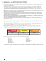 6
6
-
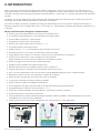 7
7
-
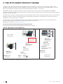 8
8
-
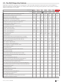 9
9
-
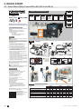 10
10
-
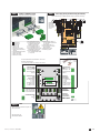 11
11
-
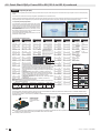 12
12
-
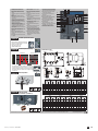 13
13
-
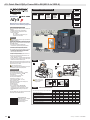 14
14
-
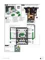 15
15
-
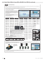 16
16
-
 17
17
-
 18
18
-
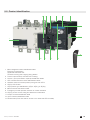 19
19
-
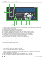 20
20
-
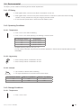 21
21
-
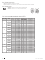 22
22
-
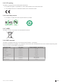 23
23
-
 24
24
-
 25
25
-
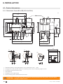 26
26
-
 27
27
-
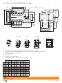 28
28
-
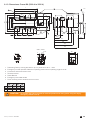 29
29
-
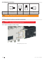 30
30
-
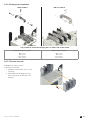 31
31
-
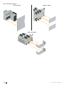 32
32
-
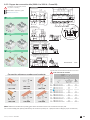 33
33
-
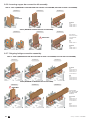 34
34
-
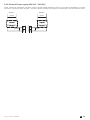 35
35
-
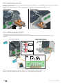 36
36
-
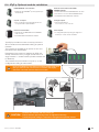 37
37
-
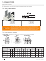 38
38
-
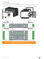 39
39
-
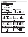 40
40
-
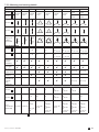 41
41
-
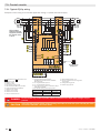 42
42
-
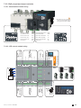 43
43
-
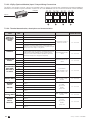 44
44
-
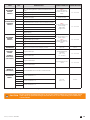 45
45
-
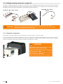 46
46
-
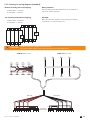 47
47
-
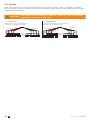 48
48
-
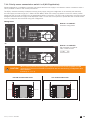 49
49
-
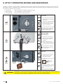 50
50
-
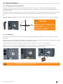 51
51
-
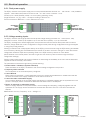 52
52
-
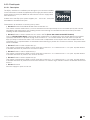 53
53
-
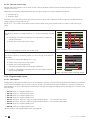 54
54
-
 55
55
-
 56
56
-
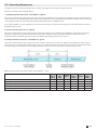 57
57
-
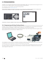 58
58
-
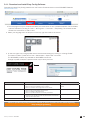 59
59
-
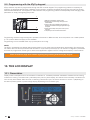 60
60
-
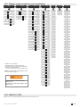 61
61
-
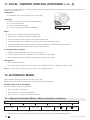 62
62
-
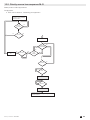 63
63
-
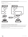 64
64
-
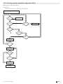 65
65
-
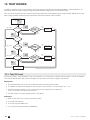 66
66
-
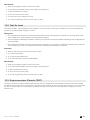 67
67
-
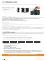 68
68
-
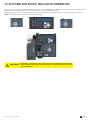 69
69
-
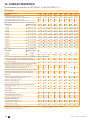 70
70
-
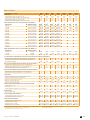 71
71
-
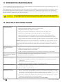 72
72
-
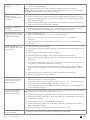 73
73
-
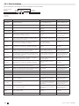 74
74
-
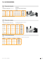 75
75
-
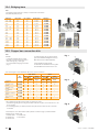 76
76
-
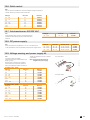 77
77
-
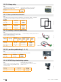 78
78
-
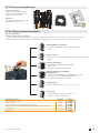 79
79
-
 80
80
-
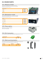 81
81
-
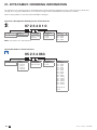 82
82
-
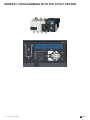 83
83
-
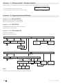 84
84
-
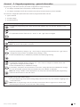 85
85
-
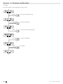 86
86
-
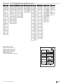 87
87
-
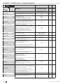 88
88
-
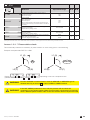 89
89
-
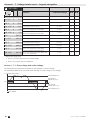 90
90
-
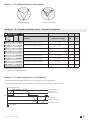 91
91
-
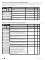 92
92
-
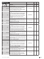 93
93
-
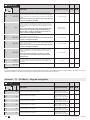 94
94
-
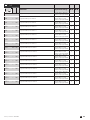 95
95
-
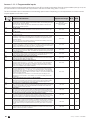 96
96
-
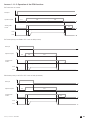 97
97
-
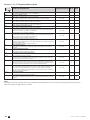 98
98
-
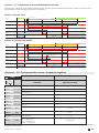 99
99
-
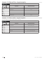 100
100
-
 101
101
-
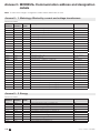 102
102
-
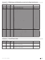 103
103
-
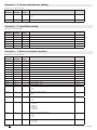 104
104
-
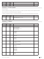 105
105
-
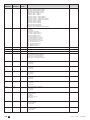 106
106
-
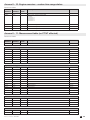 107
107
-
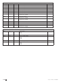 108
108
-
 109
109
-
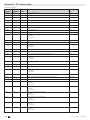 110
110
-
 111
111
-
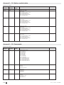 112
112
-
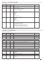 113
113
-
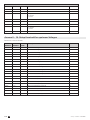 114
114
-
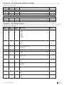 115
115
-
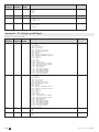 116
116
-
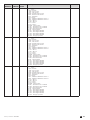 117
117
-
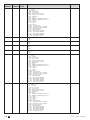 118
118
-
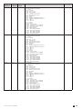 119
119
-
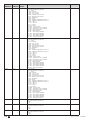 120
120
-
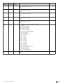 121
121
-
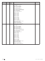 122
122
-
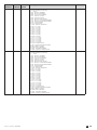 123
123
-
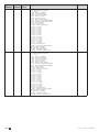 124
124
-
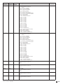 125
125
-
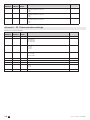 126
126
-
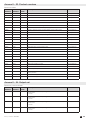 127
127
-
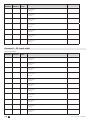 128
128
-
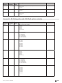 129
129
-
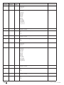 130
130
-
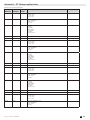 131
131
-
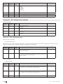 132
132
-
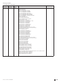 133
133
-
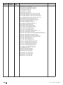 134
134
-
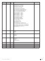 135
135
-
 136
136


Ask a question and I''ll find the answer in the document
Finding information in a document is now easier with AI
Related papers
-
Socomec ATyS g Operating instructions
-
-
Socomec ATyS t Operating instructions
-
-
Socomec ATyS r - ATyS d Operating instructions
-
-
-
Socomec ATyS C25 Operating instructions
-
-
Other documents
-
Hager HIC4 A Series Quick Start
-
UniGuard GPS Padlock Owner's manual
-
Emerson 381333234 E User manual
-
ICT ICT180S-12IRC Owner's manual
-
wanwu communication DTS866 User manual
-
Smartgen HMU15N User manual
-
Toshiba Power Supply 1700 User manual
-
 Mikro RX380 User manual
-
-
 Ditel KOS1720 User manual

