Superior Fireplaces BRT4000 Operating instructions
- Category
- Stoves
- Type
- Operating instructions
This manual is also suitable for

BRT4336TEN-B
BRT4536TEN-B
BRT4342TEN-B
BRT4542TEN-B
BRT4336TEP-B
BRT4536TEP-B
BRT4342TEP-B
BRT4542TEP-B
- Do not store or use gasoline or other flammable
vapors and liquids in the vicinity of this or any
other appliance.
- WHAT TO DO IF YOU SMELL GAS
• Do not try to light any appliance.
• Do not touch any electrical switch; do not use
any phone in your building.
• Leave the building immediately.
• Immediately call your gas supplier from a neigh-
bor’s phone. Follow the gas supplier’s instruc-
tions.
• If you cannot reach your gas supplier, call the
fire department.
- Installation and service must be performed by
a qualified installer, service agency or the gas
supplier.
WARNING:
FIRE OR EXPLOSION HAZARD
Failure to follow safety warnings exactly could
result in serious injury, death, or property damage.
AVERTISSEMENT:
RISQUED’INDENDIE OU D’EXPLOSION
Le non-respect Des avertissements de sécurité
pourrait d’entraîner des blessures graves, la mort
ou des dommages matériels.
- Ne pas entreposer ni utilizer d’essence ni d’autres
vapeurs ou liquides inflammables dans le voisinage
de cet appareil ou de tout autre appareil.
- QUE FAIRE SI VOUS SENTEZ UNE ODEUR DE GAZ:
• Ne pas tenter d’allumer d’appareil.
• Ne touchez à aucan interrupteur. Ne pas vous servir
des téléphones se trouvant dans le bâtiment où
vous trouvez.
• Sortez immédiatement de bâtiment.
• Appelez immédiatement votre fournisseur de
gaz depuis un voisin. Suivez les instructions du
fournisseur.
• Si vous ne pouvez rejoindre le fournisseur de gaz,
appelez le service des incindies.
- L’installation et l’entretien doivent être assurés par
un installateur ou un service d’entretien qualifié
ou par le fournisseur de gaz.
INSTALLER: Leave this manual with the appliance.
CONSUMER: Retain this manual for future
reference.
Installateur : Laissez cette notice avec l’appareil.
Consommateur : Conservez cette notice pour
consultation ultérieure.
Decorative Product: Not for use as a heating
appliance.
NOTICE: Fireplace is not to be operated by a
thermostat.
This appliance may be installed in an aftermarket permanently located, manufactured home (USA only) or mobile
home, where not prohibited by local codes. This appliance is only for use with the type of gas indicated on the
rating plate. This appliance is not convertible for use with other gases, unless a certified kit is used.
Cet appareil peut installé dans une maison préfabriquée (mobile) déjà installée à demeure, si les réglements
locaux le permettent. Ce appareil doit être utilisé uniquement avec le type de gaz indiqué sure la plaque
signalétique. Cet appareil ne peut être converti à d’autres gaz, sauf si une trousse de conversion est utilsée.
Installation and Operation Instructions
Models
PFS
®
USC
Report No. F09-143
Ce manuel est disponible en francais, simplement en
faire la demande. Numéro de la pièce 900807-03.
P/N 900807-00 REV. E 03/2019
Custom Series Decorative B-Vent Fireplace
Electronic Ignition System
P900807-00

SuperiorFireplaces.us.com 900807-00E2
SAFETY
Thank you for your purchase. We appreciate your
business!
Please carefully read and follow all instructions in this manual. Pay
special attention to all warnings and safety information.
Following these safety, care, and operation instructions will help
ensure many years of dependable and enjoyable service from your
fireplace.
Please read and understand these instructions before installing
or operating.
TABLE OF CONTENTS
WARNING: Improper installation, adjustment,
alteration, service or maintenance can cause injury
or property damage. Refer to this manual for correct
installation and operational procedures. For assistance
or additional information consult a qualified installer,
service agency or the gas supplier.
SAVE THIS BOOK
This book is valuable. In addition to instructing you
on how to install and maintain your appliance, it also
contains information that will enable you to obtain
replacement parts or optional accessory items when
needed. Keep it with your other important papers.
This fireplace may not be installed in manufactured
(mobile) housing constructed to HUD standards. The
fireplace may be installed in aftermarket, non-HUD
manufactured housing provided its installation com-
plies with State and Local Codes and in the absence of
these codes complies with the National Fuel Gas Code
ANSI Z223.1/NFPA 54, or the Natural Gas and Propane
Installation Code,CSA B149.1.
NOTICE: Young children should be carefully super-
vised when they are in the same room as the appli-
ance. Toddlers, young children, and others may be
susceptible to accidental burns. A physical Children
and adults should be alerted is recommended if there
are to be at-risk individuals in the house. To restrict
access to a fireplace or stove, install an adjustable
safety gate to keep toddlers, young children, and other
at-risk individuals out of and away from hot surfaces.
State of Massachusetts: The installation must be made
by a licensed plumber or gas fitter in the Commonwealth
of Massachusetts.
Due to high temperatures, the appliance should be lo-
cated out of traffic and away from furniture and draperies.
NOT FOR USE WITH SOLID FUEL CHECK LOCAL
CODES PRIOR TO INSTALLATION
Safety ............................................................................................. 2
Unpacking ...................................................................................... 4
Introduction ................................................................................... 4
Selecting Location .......................................................................... 5
Requirements for the Commonwealth of Massachusetts .............. 5
Product Specifi cations ................................................................... 6
Pre-installation Preparation ............................................................ 7
Venting Installation ........................................................................ 9
Installation ................................................................................... 11
Operation .................................................................................... 17
Inspecting Pilot And Burner Flame Patterns ................................. 18
Cleaning and Maintenance ........................................................... 18
Wiring Diagram ............................................................................ 19
Service Hints ................................................................................ 20
Technical Service ......................................................................... 20
Replacement Parts ....................................................................... 20
Troubleshooting ........................................................................... 21
Parts ............................................................................................ 23
Accessories .................................................................................. 27
Warranty ...................................................................................... 31
WARNING
This product can expose you to chemicals including
Carbon Black, which is known to the State of California
to cause cancer, and Carbon Monoxide, which is known
to the State of California to cause birth defects or other
reproductive harm. For more information go to www.
P65Warnings.ca.gov
AVERTISSEMENT
Ce produit peut vous exposer à des produits chimiques,
y compris du carbone noir qui est reconnu par l'État
de Californie comme un produit cancérigène, et du
monoxyde de carbone, qui est reconnu par l'État de
Californie comme pouvant causer des déformations
fœtales ou perturber la fonction reproductive. Pour plus
d’information, aller sur www.P65Warnings.ca.gov

SuperiorFireplaces.us.com900807-00E 3
3. If you smell gas
• shut off gas supply
• do not try to light any appliance
• Leave the building immediately.
• do not touch any electrical switch; do not use any phone in your
building
• immediately call your gas supplier from a neighbor’s phone.
Follow the gas supplier's instructions
• if you cannot reach you gas supplier, call the fire department.
4. Never install the fireplace
• in a recreational vehicle
• where curtains, furniture, clothing or other flammable objects are
less than 36" from front and 42" from top of fireplace. For side
clearances see Figure 6, Page 7
• in high traffic areas
• in windy or drafty areas
5. This fireplace reaches high temperatures. Keep children and
adults away from hot surfaces to avoid burns or clothing ignition.
Fireplace will remain hot for a time after shutdown. Allow surfaces
to cool before touching.
6. Carefully supervise young children when they are in the room with
fireplace.
7. A hearth extension is not required with this appliance. If one is
installed, it is for aesthetic purposes only and does not have to
meet the standard requirements.
8. Turn fireplace off and let cool before servicing or repairing. Only
a qualified service person should install, service or repair this
fireplace. Have fireplace inspected annually by a qualified service
person.
9. You must keep control compartments, burners and circulating air
passages clean. More frequent cleaning may be needed due to exces-
sive lint and dust from carpeting, bedding material, etc. Turn off the
gas valve and pilot light before cleaning fireplace.
10. Have venting system inspected annually by a qualified service
person. If needed, have venting system cleaned or repaired. See
Cleaning and Maintenance, Page 18.
11. Keep the area around your fireplace clear of combustible materi-
als, gasoline and other flammable vapor and liquids. Do not run
fireplace where these are used or stored. Do not place items such
as clothing or decorations on or around fireplace.
12. Do not use this fireplace to cook food or burn paper or other
objects.
13. Do not use any solid fuels (wood, coal, paper, cardboard, etc.)
in this fireplace. Use only the gas type indicated on fireplace
nameplate.
14. This appliance, when installed, must be electrically grounded in
accordance with local codes or, in the absence of local codes,
with the National Electrical Code, ANSI/NFPA 70 or the Canadian
Electrical Code, CSA C22.1.
15. Do not obstruct the flow of combustion and ventilation air in any
way. Provide adequate clearances around air openings into the
combustion chamber along with adequate accessibility clearance
for servicing and proper operation.
16. Do not install fireplace directly on carpeting, vinyl tile or any
combustible material other than wood. The fireplace must set on
a metal or wood panel extending the full width and depth of the
fireplace.
17. Do not use fireplace if any part has been exposed to or under
water. Immediately call a qualified service person to arrange for
replacement of the unit.
18. Do not operate fireplace if any log is broken.
19. Do not use a blower insert, heat exchanger insert or other acces-
sory not approved for use with this fireplace.
WARNING: This product contains and/or generates
chemicals known to the State of California to cause
cancer or birth defects or other reproductive harm.
WARNING: Any change to this fireplace or its controls
can be dangerous.
DANGER: Carbon monoxide poisoning may lead
to death!
IMPORTANT: Read this owner’s manual carefully and
completely before trying to assemble, operate or service
this fireplace. Improper use of this fireplace can cause
serious injury or death from burns, fire, explosions,
electrical shock and carbon monoxide poisoning.
This fireplace is a vented product. This fireplace will not produce any
gas leakage into your home if properly installed. This fireplace must be
properly installed by a qualified service person. If this unit is not properly
installed by a qualified service person, gas leakage can occur.
Carbon Monoxide Poisoning: Early signs of carbon monoxide poisoning
resemble the flu, with headaches, dizziness or nausea. If you have these
signs, the fireplace may not have been installed properly. Get fresh air at
once! Have fireplace inspected and serviced by a qualified service person.
Some people are more affected by carbon monoxide than others. These
include pregnant women, people with heart or lung disease or anemia,
those under the influence of alcohol and those at high altitudes.
Propane/LP gas and natural gas are both odorless. An odor-making
agent is added to each of these gases. The odor helps you detect a
gas leak. However, the odor added to these gases can fade. Gas may
be present even though no odor exists.
Make certain you read and understand all warnings. Keep this manual for
reference. It is your guide to safe and proper operation of this fireplace.
1. This appliance is only for use with the type of gas indicated on the
rating plate. This appliance is not convertible for use with other
gases unless a certified kit is used.
2. For propane/LP fireplace, do not place propane/LP supply tank(s)
inside any structure. Locate propane/LP supply tank(s) outdoors.
To prevent performance problems, do not use propane/LP fuel
tank of less than 100 lbs. capacity.
SAFETY Continued
IMPORTANT: This appliance uses room air for com-
bustion. It is imperative that provisions for adequate
combustion and ventilation air be made. This appliance
is NOT designed to and will not operate in a significant
negative pressure environment (pressure within the
home is less than pressures outside). Significant neg-
atively pressured environments caused by weather,
home design, or other devices will impact the operation
of these appliances. Negative pressures may result in
poor flame appearance, sooting, damage to property
and/or severe personal injury. Contact your dealer if
you suspect a negative pressure situation exists.

SuperiorFireplaces.us.com 900807-00E4
COMMONWEALTH OF MASSACHUSETTS REQUIREMENTS
These appliances are approved for installation in the US state of Mas-
sachusetts if the following additional requirements are met:
• Install this appliance in accordance with Massachusetts Rules and
Regulations 248 C.M.R. Sections 4.00 through 8.00.
• Installation and repair must be done by a plumber or gas fitter
licensed in the Commonwealth of Massachusetts.
• The flexible gas line connector used shall not exceed 36 inches
(92 centimeters) in length.
• The individual manual shut-off must be a T-handle type valve.
INTRODUCTION
All 36" and 42" models listed within this manual are vented gas fireplaces
that use an electronic control valve and electronic ignition system. A 6"
B-Type venting system and a listed type vent cap are not supplied but are
required for proper operation. See venting instructions on Pages 9 and 10.
WARNING: This gas appliance must not be con-
nected to a chimney flue serving a separate solid-fuel
burning appliance.
BEFORE YOU BEGIN
Before beginning the installation of your appliance, read these instruc-
tions through completely.
This INNOVATIVE HEARTH PRODUCTS, LLC (IHP) appliance and
its approved components are safe when installed according to this
installation manual and are operated as recommended by IHP. Unless
you use IHP approved components tested for this appliance, YOU
MAY CAUSE A FIRE HAZARD!
The IHP warranty will be voided by and IHP disclaims any responsibil-
ity for the following actions :
A) Modification of the appliance or any of the components.
B) Use of any component part not approved by IHP in combination
with this appliance.
C) Installation and/or operation in a manner other than instructed in
this manual.
D)
Burning of anything other than the type of gas approved for use in
this gas appliance.
UNPACKING
The following items are packed inside the firebox. Remove before
positioning firebox into framing.
• Transition Collar - For vent connection
• Ceramic Log Pack - Shrink-wrapped on cardboard
• Three (3) plastic bags containing volcanic stone rock, pan and
ember materials
• Rear Log - Remove the two plastic quick ties from around the
burner and grate
• Grate Stand - Lift off of burner pan
Check all items for any shipping damage. If damaged, promptly inform
dealer or distributor where you purchased the product.
Safely retain these items for later installation.
CODES AND STANDARDS
These fireplaces comply with National Safety Standards and are
tested and listed by PFS Corporation (Report No. F09-143) to ANSI
Z21.50 (in Canada, CSA-2.22) in both USA and Canada, as vented
gas fireplaces. The installation must conform to local codes or, in the
absence of local codes, with the National Fuel Gas Code, ANSI Z223.1/
NFPA 54—latest edition (In Canada, the current CAN/CGA-B149.1
installation code). The fireplace, when installed, must be electrically
grounded and wired in accordance with local codes or, in the absence
of local codes, with the National Electrical Code, ANSI/NFPA 70—lat-
est edition, or the Canadian Electrical Code, CSA C22.1—latest edition.
These appliances comply with CSA P.4.1-2015 “Testing Method for
Measuring Annual Fireplace Efficiency. P4 (EnerGuide) is a measure-
ment of the Canadian Office of Energy Efficiency.
SAFETY Continued
20. Provide adequate clearances around air openings.
21. Children and adults should be alerted to the hazards of high sur-
face temperature and should stay away to avoid burns or clothing
ignition.
22. Clothing or other flammable material should not be placed on or
near the appliance.
23. The draft hood be installed so as to be in the same atmospheric
pressure zone as the combustion air inlet to the appliance and
shall be located so that the relief opening is accessible for checking
vent operation.
Based on CSA P. 4.1-2015

SuperiorFireplaces.us.com900807-00E 5
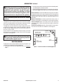
INTRODUCTION Continued
2. Consider a location where heat output would not be affected by drafts,
air conditioning ducts, windows or doors.
3. A location that avoids the cutting of joists or roof rafters will make instal-
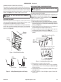
lation easier. Figure 1 shows a plan view of a few common locations.
Flush installations are recommended where living space is limited or
at a premium and since the space required to enclose the appliance
would be located beyond an outside wall, this would also reduce the
cutting of joists, roof rafters and such. Check local codes for any
restrictions.
Projected installations can extend any distance into the room. A
projection may be ideal for a new addition on an existing, finished wall.
Corner installations make use of space that may not normally be
used and provides a wider and more efficient range for radiant heat
transference.
Internal wall installations provide a discreet option for room separa-
tion and can also be ideal as an addition to an existing wall.
Figure 1 - Possible Locations for Installing Appliance
INTERNAL WALL
INSTALLATION
CORNER
INSTALLATION
FULL
PROJECTION
INSTALLATION
FLUSH
INSTALLATION
WARNING: Installation of this appliance should be
done by a qualified service person well trained in the
installation of such appliances. You will also need a
building permit from your local Building and Safety
Commissioner before installing this appliance; other-
wise your insurance co. may not cover this appliance.
NOTICE: Decorative product not for use as a heating
appliance.
The appliance and it’s individual shutoff valve must be disconnected
from the gas supply piping system during any pressure testing of
that system at test pressures in excess of 1/2 psi (3.5 kPa).
The appliance must be isolated from the gas supply piping system
by closing its individual manual shutoff valve during any pressure
testing of the gas supply piping system at test pressures equal to or
less than 1/2 psi (3.5 kPa).
For the purpose of input adjustment two pressure taps (for IN and
OUT pressures) are provided on the gas control valve for test gauge
connections to the appliance.
SELECTING LOCATION
To determine the safest and most efficient location for your appliance, you
must take into consideration the following guidelines:
1. The location must allow for proper clearances (see Clearances,
Page 7).
CAUTION: Do not connect appliance before pressure
testing gas piping. Damage to gas valve may result and
an unsafe condition may be caused.

SuperiorFireplaces.us.com 900807-00E6
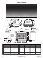
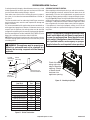
PRODUCT SPECIFICATIONS
X
Outside Air
Kit Location
(Optional)
Glass Door
(Optional)
Alternate Gas
Supply Inlet
7" (178 mm)
7"
(178 mm)
7" (178 mm)
1-1/2" (38 mm)
13-1/2" (343 mm)
A
E
F
R
P
Q
S
I
J
L
N
O
W
V
M
K
T
G
H
D
C
B
Stand Off
Collar
For Use With
6"Ø Type B-1
Vent Pipe Only
DIMENSIONS
HEARTH AREA
Figure 2 - Appliance Dimensions
GAS RATING - NATURAL
BRT 4336TEN-B, 4536TEN-B BRT 4342TEN-B, 4542TEN-B
Max. Input Rating: 40,000 Btu/Hr 45,000 Btu/Hr
Manifold Pressure: 3.5" WC (.87 kPa) 3.5" WC (.87 kPa)
Minimum Supply Pressure: 4.5" WC (1.12 kPa) 4.5" WC (1.12 kPa)
Maximum Supply Pressure: 10.5" WC (2.62 kPa) 10.5" WC (2.62 kPa)
Orifice Size: # 31 # 29
GAS RATING - PROPANE/LP
BRT 4336TEP-B, 4536TEP-B BRT 4342TEP-B, 4542TEP-B
Max. Input Rating: 40,000 Btu/Hr 45,000 Btu/Hr
Manifold Pressure: 10" WC (2.50 kPa) 10" WC (2.50 kPa)
Minimum Supply Pressure: 11" WC (2.74 kPa) 11" WC (2.74 kPa)
Maximum Supply Pressure: 13" WC (3.23 kPa) 13" WC (3.23 kPa)
Orifice Size: # 52 # 50
Model 36 Model 42 Model 36 Model 42 Model 36 Model 42
A 29" (737 mm) 36" (915 mm) I 40
1
/
4
" (1023 mm) 44
1
/
4
" (1124 mm) Q 13
7
/
8
" (353 mm) 14" (356 mm)
B 5/8" (16 mm) 5/8" (16 mm) J 21" (534 mm) 24" (610 mm) R 10
1
/
2
" (267 mm) 12
1
/
2
" (318 mm)
C 41" (1042 mm) 48" (1220 mm) K 8" (204 mm) 9" (229 mm) S 2
1
/
2
" (64 mm) 2
1
/
2
" (64 mm)
D 12" (305 mm) 14" (356 mm) L 34
3
/
4
" (883 mm) 42" (1067 mm) T 8
1
/
8
" (207 mm) 8
1
/
8
" (207 mm)
E 21
1
/
4
" (540 mm) 23" (585 mm) M 42" (1067 mm) 49" (1245 mm) U 11" (280 mm) 12
3
/
4
" (324 mm)
F 22
1
/
4
" (566 mm)
24" (610 mm) w/o Brick
29
1
/
4
" (743mm)
31" (788 mm) w/o Brick
N 36" (915 mm) 40" (1016 mm) V 7" (178 mm) 7" (178 mm)
G 32
5
/
8
" (829 mm)
34" ( 864 mm) w/o Brick
39
1
/
2
" (1004 mm)
41
1
/
4
" (1048 mm) w/o Brick
O 37" (940 mm) 41" (1042 mm) W 2
1
/
4
" (58 mm) 2
1
/
4
" (58 mm)
H 15
3
/
4
" (400 mm)
16
3
/
4
" (426 mm) w/o Brick
17
3
/
4
" (451 mm)
18
3
/
4
" (477 mm) w/o Brick
P 8
5
/
8
" (220 mm) 10
1
/
2
" (267 mm) X 5" (127 mm) 4
1
/
2
" (115 mm)

SuperiorFireplaces.us.com900807-00E 7
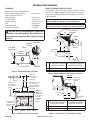
PRE-INSTALLATION PREPARATION
Figure 3 - Minimum Clearances (Top View)
0 cm/
po
0 cm/po
Clearance
Nailing
Flange
Front Face
Left Side
Surround
Back
Drywall
2 x 4 Stud
Figure 4 - Minimum Clearances (Front View)
*
*
**
42" (106.7 cm)
Min. Clearance
from Opening to
Ceiling
0" Clearance
Ceiling
1" (2.5 cm)
Min. Clearance
to "B" Vent's
Outer Pipe
Maintain 2" (5.1 cm)
Min. Clearance to
Transition Pipe as
Measured at Outer
Vent Collar
Required air
spaces are
indicated with
an "
*
". Do not
pack with
insulation or
any other
material.
DO NOT BLOCK
OR OBSTRUCT
OPENINGS
0" Clearance to
Combustible or
Noncombustible
Flooring
Spacer
3" (7.6 cm)
1
1
/
2
"
(3.8 cm) Max.
B
6" (15.2 cm)
A
12"
(22.9 cm)
Combustible
Materials
Header
Figure 5 - Mantel Clearances - Side View (Cross Section)
Figure 6 - Side Clearances - Top View (Cross Section)
CLEARANCES
Minimum clearances to combustibles are:
Back and Sides of Outer Surround 0" (0 mm) min.
Drywall to Sides of Front Face
(Nailing Flanges) 0" (0 mm) min.
“B” Vent Surfaces 1" (26 mm) min.
Ceiling to Opening 42" (1067 mm) min.
Floor 0" (0 mm) min.
Perpendicular Wall See Figure 6
Front Service Clearances 3' (0.9 M)
BRT 4336TEN-B, 4536TEN-B,
4336TEP-B, 4536TEP-B
BRT 4342TEN-B, 4542TEN-B,
4342TEP-B, 4542TEP-B
A
9" (229 mm) 6" (153 mm)
B
12" (305 mm) 9" (229 mm)
BRT 4336TEN-B, 4536TEN-B,
4336TEP-B, 4536TEP-B
BRT 4342TEN-B, 4542TEN-B,
4342TEP-B, 4542TEP-B
A
14" (35.6 cm) 15" (38 cm)
B
8" (20.3 cm) 9" (22.9 cm)
MANTEL CLEARANCES AND WALL DETAILS
A combustible mantel shelf maybe installed a maximum 12" (22.9
cm) from wall. Figures 5 and 6 show the minimum allowable dis-
tances from various combustible mantel components in relation to
fireplace opening.
CAUTION: Do not block required air spaces with
insulation or any other material. Do not obstruct ef-
fective opening of appliance with any type of facing
material.
Minimum clearance requirements include any projections such as
shelves, window sills, mantels, etc. above the appliance.
1
1
/
2
"
(3.8 cm)
Max.
3" (7.6 cm)
Max.
6" (15.2 cm)
Max.
A
B
Outer Surround
Combustible
Material May
Be Used
TOP VIEW
SAFE
ZONE
Perpendicular
Wall
NOTE: To avoid heat-related finish damage, we recommend the use of high
temperature paint (rated 175° F or higher) on the underside of the mantel.

SuperiorFireplaces.us.com 900807-00E8
PRE-INSTALLATION PREPARATION Continued
Figure 7 - Rough Opening for Installing in Wall
B
C
A
Figure 8 - Corner Installation Guidelines
A
B
C
D
These Dimensions Allow for a 3/4" Clearance
at Sides and Back of Fireplace. However, 0"
Clearance is Permitted
3/4" Clearance Not
Required at Nailing Flanges
Figure 9 - Installing Transition Pipe and Starter Collar
B-Vent Piping
Transition Pipe
Starter Collar
Vent Collar
36 INCH MODELS 42 INCH MODELS
A
40
3
/
8
" (102 cm) 44
3
/
8
" (112 cm)
B
21
3
/
8
" (54.3 cm) 23
1
/
8
" (58.7 cm)
C
41
1
/
4
" (104.8 cm) 48
1
/
4
" (122.6 cm)
BRT 4336TEN, 4536TEN,
4336TEP, 4536TEP
BRT 4342TEN, 4542TEN,
4342TEP, 4542TEP
A
24
1
/
2
" (62.2 cm) 27
9
/
16
" (70 cm)
B
73
7
/
8
" (187.6 cm) 83
7
/
8
" (213 cm)
C
52
3
/
16
" (132.6 cm) 59
5
/
16
" (150.6 cm)
D
17
1
/
4
" (43.8 cm) 19
1
/
2
" (49.5 cm)
FRAMING
1. Frame appliance enclosure as illustrated in Figures 7 and 8.
NOTE: If a wall covering is used to line enclosure, then all measurements
must be from surface of covering.
2. Place appliance into framing and secure.
NOTE: If appliance is to be raised above floor level, a platform must be
built to support appliance.
3. Install supply line to appliance using a 1/2" NPT black iron gas line
terminating 2-5/16" above bottom of appliance. The gas line must be
installed through lower left side access point or alternate access hole
in the bottom of appliance (see Figure 17, Page 12).
4. Repack insulation around gas line to cover any remaining openings in
conduit sleeve. Prepare incoming gas line with teflon tape or pipe joint
compound and hook up incoming gas line to flexible gas line.
NOTE: If 1/2" NPT black iron pipe does not mate with fitting at the end
of flexible gas line, remove fitting and replace with a 37 degree flare
3/4"-12, 1/2" NPT (female) fitting.
INSTALLING TRANSITION PIPE AND STARTER COLLAR
The transition pipe and starter collar shown in Figure 9 are supplied
with fireplace, unattached and ready for installation. Remove starter
collar and set aside. Slide transition pipe over vent collar and attach
with a minimum of three screws. Replace starter collar over transition
pipe and attach using four screws located on leg stands (five used
on 42" models). To install B-vent piping, slide first piece of B-vent
over transition pipe and attach with either a minimum of two screws
or other means approved by the vent manufacturer.
WARNING: When finishing appliance, do not
overlap combustible material onto the black front
face. Brick, tile or other noncombustible materials
may be applied to the face provided that any gap is
between the material used and the face is caulked
with a noncombustible caulking.

SuperiorFireplaces.us.com900807-00E 9
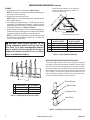
VENTING INSTALLATION
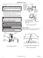
Example 2: Shows a multiple offset each at 45° of inclination. Mul-
tiple offsets are permitted if they do not exceed 45° of inclination.
The total lengths of the two offsets are not required to meet the 75%
allowable rule.
Example 3: Shows a single offset at 45° of inclination and therefore
the lateral length at 10 feet of offset does not have to meet the 75%
rule.
In each case the offsets must be supported and firestops must be
positioned wherever the vent must pass through a sub-floor, ceiling
joist or an attic overhang. The vent pipe must terminate vertically into a
listed type vent cap and extend a sufficient height through an approved
roof flashing, roof jack or a roof thimble (38FST recommended). At
all points the listed clearances must be maintained.
Vent terminations must be located in accordance with height and
proximity rules of ANSI Z223.1/NFPA 54, or the Natural Gas and
Propane Installation Code, CSA B149.1. These rules apply to vents
at 12" diameter or less and require a minimum height in accordance
with the roof pitch and a minimum of 8 ft. distance from a vertical
wall or obstruction (see Figure 11, Page 10).
A B-type venting system must be connected to appliance for venting
to the outside of building.
The following section is provided as a guide to a standard B-type
vent installation.
Standing codes requirements concerning B-type vent installations
may vary within your state, province or local codes jurisdiction.
Therefore, it is recommended that you check with your local building
codes for specific requirements or in absence of local codes, follow
"Venting of Equipment" section of the current National Fuel Gas Code
ANSI Z223.1/NFPA 54, or the Natural Gas and Propane Installation
Code, CSA B149.1.
This gas appliance must be vented to the outdoors only and may not
be terminated into an attic space or into a chimney flue servicing a
solid-fuel burning appliance.
This appliance may be vented through a manufactured chimney
system or a masonry chimney using a B-vent adaptor or a chimney
liner system if all are listed, inspected and approved by local codes
and/or building authorities.
The examples shown in Figure 10 are typical of most B-vent installa-
tions and codes practices. A minimum of 3 feet vertical rise (off the
top of the unit) before offset is recommended.
Example 1: Shows the minimum allowable system height and lateral
offset for a 60° or greater inclination. Code specifies that offsets at
60° or greater are considered horizontal and must follow the 75%
rule for lateral to total vertical system height. Codes also allow only
one offset in the total system when at 60° or greater. The total vertical
height in this example represents the minimum height of 8 feet and
therefore the allowable lateral is 6 feet when the 75% rule applies. If
the lateral length must exceed 75% then the system must be sized
in accordance with the Category I venting tables.
Maintain
Listed
Clearance
Maintain
Listed
Clearance
12' Min.
12' Min.
45°
45°
6'
8'
12' Min.
60°
45°
Position
Firestop
Position
Firestop
Position
Firestop
Listed
Vent Cap
Listed
Vent Cap
Listed
Vent Cap
Maintain
Listed
Clearance
Maintain
Listed
Clearance
Maintain
Listed
Clearance
Maintain
Listed
Clearance
Support Each
Lateral At
Least Every
6 Feet
Maintain
Listed
Clearance
10'
EXAMPLE 3EXAMPLE 2
EXAMPLE 1
Figure 10 - Typical B-Vent Configuration
IMPORTANT NOTICE
ANSI Z223.1/NFPA 54 (USA), or CSA B149.1 (Canada)
defines minimum space requirements for the instal-
lation of this appliance.
This fireplace must be installed in an unconfined space
with a minimum of 50 cubic feet per 1,000 BTUs of gas
output. Therefore 36” models require 2,650 cubic feet,
42” models require 3,100 cubic feet and 50” models
require 3,300 cubic feet. If the space you wish to in-
stall the fireplace does not meet these requirements
ANSI Z223.1/NFPA 54 or CSA B149.1 details several
actions that may be taken.

SuperiorFireplaces.us.com 900807-00E10
VENTING INSTALLATION Continued
If venting horizontally through a side wall becomes necessary, a listed
thimble approved for use with B-type vent must be used. Check with
your local codes before venting through a side wall.
Some codes areas allow the use of existing B-type vent systems if
the system is at or above the recommended diameter of the flue, in
this case 6".
The flue connection must be made using listed B-type connectors
and the existing system must be code inspected for damage and
proper installation.
It is not recommended that this appliance be common vented with an
existing gas burning appliance. However, if it becomes necessary to
common vent this appliance, the venting system must be sized and
configured in accordance with the common venting guides Appendix
G of the current National Fuel Gas Code ANSI Z223.1/NFPA 54, or the
Natural Gas and Propane Installation Code, CSA B149.1.
NOTE: Before connecting this appliance to an existing vent system or
a common venting system consult with your local architect, planner
or building official.
Lowest
Discharge
Opening
Listed
Vent Cap
8 Ft. Min.
Roof Pitch x/12
Listed Clearance
12
x
Listed
Gas
Vent
H (Min)
Height
From Roof
Figure 11 - B-Vent Terminations
Roof Pitch
H (Min.)
Feet Meter
Flat to 6/12 1.0 0.30
6/12 to 7/12 1.25 0.38
Over 7/12 to 8/12 1.5 0.46
Over 8/12 to 9/12 2.0 0.61
Over 9/12 to 10/12 2.5 0.76
Over 10/12 to 11/12 3.25 0.99
Over 11/12 to 12/12 4.0 1.22
Over 12/12 to 14/12 5.0 1.52
Over 14/12 to 16/12 6.0 1.83
Over 16/12 to 18/12 7.0 2.13
Over 18/12 to 20/12 7.5 2.27
Over 20/12 to 21/12 8.0 2.44
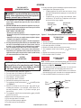
CHECKING FOR PROPER VENTING
After completing and checking electrical, gas and vent connections,
follow the lighting instructions and allow the main burner to run for
approximately 5 minutes. Hold a lighted match or cigarette near the
top edge of fireplace opening and play it along entire length of open-
ing (see Figure 12). Proper venting should tend to draw the flame or
smoke into the appliance. Improper venting or escaping of spillage of
burned gas, is indicated when the match flickers or goes out. Smoke
from a cigarette will also tend to disperse away from the appliance.
If the appliance is found to be improperly venting, shut it off and
notify your installer or a qualified service agency to inspect the vent-
ing system.
Figure 12 - Checking for Spillage
Check this area
along entire top
edge of replace
opening. Smoke
or ame should
be drawn into
appliance opening.
WARNING: This appliance must be properly con-
nected to a system and must not be connected to a
chimney flue servicing a separate solid fuel burning
appliance.
NOTICE: This appliance is equipped with a vent safety
shutoff switch which will shut down the appliance in
the case of a venting problem. Do not bypass the vent
safety switch. If the appliance should shut down, con-
tact a qualified installer, service agency or your gas
supplier to have the vent inspected before operating.

SuperiorFireplaces.us.com900807-00E 11
INSTALLATION
Figure 13 - Removing Front Refractory Access Panel
Figure 14 - Installing WRC Remote Receiver
Fireplace
Receptacle
Remote
Control
Receiver
Extension Cord
Ignition
Module Plug
WALL SWITCH INSTALLATION
The installation of a wall switch allows you to activate the gas con-
trol valve and turn the fireplace on and off. The wall switch is to be
connected to the incoming 120 volt regular household wiring that
supplies electricity to the fireplace. Refer to wiring diagram in this
manual on Page 19.
OPTIONAL REMOTE CONTROL INSTALLATION (Model WRC)
NOTE: If using optional wireless hand-held remote control, wall switch
must be in the ON position to be operational. The remote control then
becomes the switching mechanism for fireplace operation.
1. Remove front refractory access panel by lifting up and angling
out of firebox opening (see Figure 13).
2. The WRC model receiver does not require a battery. Receiver can
be installed by plugging the short extension cord into fireplace
receptacle. Plug receiver unit into extension cord. Plug ignition
module plug into receiver unit (see Figure 14).
3. Activate remote handset battery by removing insulating tab on
back of handset (see Figure 15). Battery is included pre-installed.
4. Once the battery is activated unit is ready to use.
5. Replace front refractory access panel.
Figure 16 - Manual Shutoff Valve Installation
Typical Exterior Wall Gas Shutoff Installation
Key
Extension
Shutoff
Valve
Figure 15 - Installing Battery into Back of Handset
Pull to Remove
Insulation Tab
Battery Cover
12 Volt Battery
Back of
Handset
WARNING: Gas line hookup should be done by your
gas supplier or a qualified service person.
WARNING: Before you proceed, make sure your
gas supply is OFF.
CAUTION: Do not kink flexible gas line.
GAS LINE HOOK-UP
A manual shutoff valve has been included in the appliance’s gas sup-
ply system. You may consider installing an extra gas shutoff valve
outside appliance’s enclosure (check with local codes) where it can
be accessed more conveniently with a key through a wall as shown
in Figure 16.
In conformance with local codes, route a 1/2" NPT gas line to appliance
through hole in left side of firebox or sub-floor as shown in Figure 17.
IHP recommends that a black iron gas line be routed from the gas
source, through a sediment trap (shown in Figure 18, Page 12) and
into appliance. Once connected through appliance, a flexible gas line
may be used for ease of installation to gas control valve (see Figure
19, Page 11).
Before connecting black iron gas line to inside of appliance a sediment
trap must be included outside appliance between gas line and gas
shutoff valve. It must extend down 3" beyond center of pipe. Prepare
incoming black iron gas line with teflon tape or pipe joint compound
(Check with local building codes).

SuperiorFireplaces.us.com 900807-00E12
INSTALLATION Continued
A
B
1/2" NPT Incoming
Black Iron Gas Line
Flexible Gas Line
(1 Provided) Can
Be Extended Out
Either Side
7"
7"
Alternate Gas Supply
Through Sub-Floor
Figure 18 - Sediment Trap
Figure 17 - Routing Incoming Gas Line
3" Min.
(7.6 cm)
Side Wall
Of Appliance
Incoming 1/2" Gas
Line Permitted by
Local Codes
Sediment
Trap (Not
Supplied)
BRT, 4336TEN-B, 4536TEN-B,
4336TEP-B, 4536TEP-B
BRT 4342TEN-B, 4542TEN-B,
4342TEP-B, 4542TEP-B
A
8
5
/
8
" (21.9 cm) 10
1
/
2
" (26.7 cm)
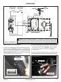
Figure 19 - Connecting Flexible Gas Line to Millivolt Valve
P
I
L
O
T
ON
OFF
IN OUT
Gas Shutoff
Valve
Flexible Gas Line
Do NOT Kink
1/2" NPT
Incoming
Gas Line
NOTE:
1) Wire Connections
Not Shown for Clarity
2) * 1/8" NPT Plugged
Tapping
Red Surface Indicates For
Propane/LP Use Only
Pilot
Adj
Inlet Pressure Tap
Outlet
Pressure Tap
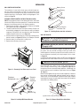
Figure 20 - Place Vermiculite on Burner Pan per Instructions
Figure 21 - Ember Material on Surface of Pan Material (Vermiculite)
Vermiculite
(Pan Material)
Burner Pan
Grate
Ember
Material
Burner
Pan
Vermiculite (Pan Material)
Grate
EMBER AND PAN MATERIAL PLACEMENT
1. Open bag(s) of vermiculite and fill until it is even across burner
pan (see Figure 20).
2. Smooth pan material just even with edges of burner pan.
3. Remove ember material from bag and flatten small amounts into
quarter size pieces and lay on top of surface of pan material (see
Figure 21).
4. Place just enough ember material to cover burner pan material.
Leave a 1/2" space between pieces.
CAUTION: Compounds used on threaded joints of
gas piping shall be resistant to the action of Liquefied
Petroleum (LP or propane) and should be applied lightly
to ensure excess sealant does not enter the gas line.
WARNING: All gas piping and connections must be
tested for leaks after the installation is completed.
After ensuring that the gas valve is on, apply a com-
mercial leak detection solution to all connections and
joints. If bubbles appear, leaks can be detected and
corrected.
Do not use an open flame for leak testing and do not
operate any appliance if a leak is detected.
Complete your gas installation by connecting incoming gas line
with flexible gas line. Secure tightly with wrench but DO NOT OVER-
TIGHTEN.
Figure 22 - Completed Installation of Vermiculite and Embers

SuperiorFireplaces.us.com900807-00E 13
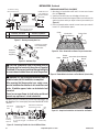
Figure 23 - Installing Logs 1 and 2
Figure 24 - Installing Logs 3 and 4
Figure 25 - Installing Logs 5 and 6
INSTALLATION Continued
LOG PLACEMENT FOR MODEL BRT 4336TEN-B, 4536TEN-B,
4336TEP-B, 4536TEP-B
1. Place small front right log (log 1) on right front of grate as shown
in Figure 23.
2. Place large back log (log 2) onto grate making sure notches rest
over grate as shown in Figure 23.
3. Place log 3 into notch on log 2, resting front end on top of log 1
(see Figure 24).
4. Place upper end of log 4 into notch on log 2 as shown in Figure
24. Rest lower end of log 4 onto middle grate finger as shown in
Figure 25.
5. Place upper end of log 5 into notch on left of log 2 (see Figure
25). Rest lower end of log 5 on grate as shown in Figure 26.
6. Insert lower end of log 6 between first two grate fingers as
shown in Figure 26 and position upper end of log 6 into notched
area on front of log 2 as shown in Figure 26.
As an option to enhance the look of the hearth, you may place volcanic
stone provided around front and sides of burner.
NOTE: It is important to ensure proper log placement per the manual
when installing these units. Verify pilot flame is not obstructed. See
Inspecting Pilot and Burner Flame Patterns on Page 18.
NOTICE: Do not put volcanic stone inside the burner
pan or around the air mixer fitting. Placing volcanic
stone inside the burner pan or blocking the openings
of the propane/LP air mixer could cause performance
problems.
1 J4246 LOG, FIREPIT SPLIT 9"
2 J7241 LOG, REAR 22"
3 J4242 LOG, TOP ROUND 11-3/4"
4 J4243 LOG, TOP SPLIT 16"
5 J4244 LOG, Y TOP SPLIT 13-1/2"
6 J4245 LOG, TOP 11"
Log 1
Log 2
Notch
Log 3
Log 4
Notches
1
2
Log 5
Log 6
Notch
Notch
3
4
2
1
Figure 26 - Logs Installed for 36" Models
1
2
3
4
5
6

SuperiorFireplaces.us.com 900807-00E14
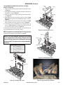
INSTALLATION Continued
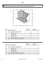
LOG PLACEMENT FOR MODEL BRT 4342TEN-B, 4542TEN-B,
4342TEP, 4542TEP
1. Place large back log (log 1) onto grate making sure notches
rest over grate (see Figure 27).
2. Insert lower end of log 2A between first two grate fingers and posi-
tion upper end into notch on front of log 1. See Figure 27. Place
log 2B on front right side of grate as shown in Figure 27.
3. Place log 3 into notch on top left of log 1, resting lower end on
left two grate fingers (see Figure 28).
4. Place upper end of log 4 into notch on log 1 as shown in Figure
28. Rest lower end of log 4 on the middle grate finger as shown
in Figure 29.
5. Place upper end of log 5 into notch on top inner right of log 1
(see Figure 29). Rest lower end of log 5 on middle grate finger
as shown in Figure 30.
6. Place log 6 into notch on top right of log 1 (see Figure 29). Rest
lower end of log 6 on top of log 2B (see Figure 30).
As an option to enhance the look of the hearth, you may place volcanic
stone provided around front and sides of burner pan.
NOTE: It is important to ensure proper log placement per the manual
when installing these units. Verify pilot flame is not obstructed. See
Inspecting Pilot and Burner Flame Patterns on Page 18.
Figure 27 - Installing Logs 1, 2A and 2B
NOTICE: Do not put volcanic stone inside the burner
pan or around the air mixer fitting. Placing volcanic
stone inside the burner pan or blocking the openings
of the propane/LP air mixer could cause performance
problems.
Log 2A
Log 2B
Log 1
Notch
1 J7242 Log, Rear 27"
2A J4245 Log, Top 11"
2B J4262 Log, Fire Pit Rnd "Y" 15-3/4"
3 J4244 Log, Y Top Split 13-1/2"
4 J4261 Log, Firepit Split 15-3/4"
5 J4243 Log, Top Split 16"
6 J4242 Log, Top Round 11-3/4"
Figure 28 - Installing Logs 3 and 4
Figure 29 - Installing Logs 5 and 6
Figure 30 - Logs Installed for 42" Models
1
3
4
5 6
2
A
2
B
1
2
B
3
4
Log 6
Log 5
Notch
Log 4
Log 3
Notches
1
2
B
2
A
2
A

SuperiorFireplaces.us.com900807-00E 15
Figure 31 - Air Kit Handle Location
Air Kit
Handle
Screen
Pocket
Figure 32 - Sealing Between Appliance and Framing
Side
Framing
Side
Framing
Caulk Here
Pack Insulation
Figure 33 - Installing Optional Glass Door
Spring Clip
Insert Pin Into Spring Clip
Insert Bottom Pivot Pin Into
Pivot Plate and Swing Door
Into Vertical Position
Pivot Plate
Slide Top
Pin Into
Door Track
INSTALLATION Continued
6. Repeat process for opposite door assembly.
7. To adjust doors, slide them partially open. Using a screwdriver,
loosen hold-down screws in the spring clip (see Figure 34, Page
16) and pivot plate.
8. Close both doors until evenly joined at the middle and note gap at
outer edges of face.
9. Reopen one door at a time and retighten upper and lower hold-
down screws.
CAUTION: Air inlet ducts are not to terminate in
attic space.
CAUTION: Use only glass doors certified for use
with this appliance.
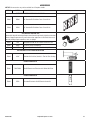
COMBUSTION AIR KIT MODEL AK4 (OPTIONAL)
The outside air kit may be installed on the left side of fireplace only.
The vent can be installed through any outside wall a minimum of three
feet below fireplace termination cap. The handle to operate damper
door for outside air inlet will be located inside left “screen pocket” of
firebox (see Figure 31). Pull handle to open or push to close.
APPLIANCE ENCLOSURE
Before finishing enclosure around appliance, inspect all joints around
outer surround. Any gaps between nailing flanges and framing should
be sealed with noncombustible insulation or caulking.
If appliance is mounted on a raised platform, it must be a continuous
surface and not on blocks without a solid surface. This will prevent
entry of cold air by means of conduction through the total bottom of
appliance (see Figure 32).
INSTALLING OPTIONAL GLASS DOOR ACCESSORY
NOTE: Glass door may be heavy for some individuals. If this is the
case, please request help if needed.
The BRT4336, BRT4536, BRT4342 and BRT4542 B-vent fireplaces are
approved for use with optional bi-fold glass doors (see Accessories,
Page 27). Glass panels may be ordered and installed anytime after
fireplace installation is complete.
Follow these steps to install left and right panels:
1. With handle at the bottom, completely fold panel on its hinges.
2. With handle facing center of firebox opening, insert lower pivot pin on
glass door panel into hole in pivot plate on bottom edge of fireplace
opening (see Figure 33).
3. Keeping folded door tilted, slide upper two pins into guide track
found under upper facial edge of firebox opening.
4. Tilt glass assembly fully vertical until outer pivot pin snaps into
mounting hole in upper spring clip (see Figure 33).
5. Once top and bottom pins are secured, unfold door into the closed
position.

SuperiorFireplaces.us.com 900807-00E16
INSTALLATION Continued
Figure 34 - Adjusting Glass Doors
Spring
Clip
Hold-Down
Screw
Side
Front
Face
Partially
Opened
Door
Figure 35 - Removing Glass Doors
Spring Clip
Press
Spring Clip
to Release
Pivot Pin
Remove Bottom Pin
From Pivot Plate While
Sliding Door Out of the
Upper Track
Pivot Plate
Fold Bi-Fold
Door After
Releasing
Spring Clip
and Slide
Door Out of
Upper Track
CLOSEOPEN
VENT DAMPER MUST BE LOCKED
IN THE FULL OPEN POSITION
TO OPERATE THE APPLIANCE
Figure 36 - Opening Vent Damper
OPENING VENT DAMPER
Vent damper must be locked in the full open position before operating
fireplace. If vent damper is not open, fireplace will not light.
CAUTION: The glass panels become very hot while
the appliance is operating. Do not attempt to adjust
or clean the glass doors until the appliance has fully
cooled.
CAUTION: Always operate the appliance with the
doors either fully opened or fully closed. Operating
the appliance with the doors partially open can result
in improper venting of flue products.
WARNING: Discontinue use of the appliance im-
mediately if doors are damaged and contact a quali-
fied installer for repair. Only doors certified with the
appliance shall be used.
WARNING: Do not slam or strike doors. Damage
can result in a hazardous condition.
10. Repeat process until both doors are evenly joined, spaced and
working freely.
The doors may be removed for replacement or cleaning as follows:
1. Partially open door and press up on upper spring clip with a screw
driver until outer top pivot pin is free of clip.
2. Fully fold frame assembly and slide upper edge towards center of
firebox opening until guide pins are free of frame rail (see Figure 35).

SuperiorFireplaces.us.com900807-00E 17
OPERATION
14. Visually locate pilot. Igniter should begin to spark and main burner
should ignite once flame appears at pilot.
• If lighting appliance for the first time each season, it may
take several attempts before supply gas can reach pilot and
main burner.
• If appliance will not stay lit after several attempts, follow
instructions in To Turn Off Gas To Appliance, and call your
service technician or gas supplier.
Figure 37 - Turning Equipment Shutoff Valve to the OFF Position
Equipment
Shutoff Valve
Adjustment
Screw
`FOR YOUR SAFETY
READ BEFORE LIGHTING
WARNING: If you do not follow these instructions
exactly, a fire or explosion may result causing property
damage, personal injury or loss of life.
A. This appliance has a pilot that is equipped with an ignition
device which automatically lights the pilot. Do not light the
pilot by hand.
B. BEFORE LIGHTING smell all around the appliance area for gas.
Be sure to smell next to the floor because some gas is heavier
than air and will settle on the floor.
WHAT TO DO IF YOU SMELL GAS
• Do not try to light any appliance.
• Do not touch any electric switch; do not use any phone in your
building.
• Immediately call your gas supplier from a neighbor’s phone.
Follow the gas supplier’s instructions.
• If you cannot reach your gas supplier, call the fire department.
C. Use only your hand to push in or turn the gas control knob. Never
use tools. If the knob will not push in or turn by hand, don’t try
to repair it, call a qualified service technician or gas supplier.
Force or attempted repair may result in a fire or explosion.
D. Do not use this appliance if any part has been under water.
Immediately call a qualified service technician to inspect the
appliance and to replace any part of the control system and any
gas control which has been under water.
LIGHTING
INSTRUCTIONS
NOTICE: During initial operation of new fireplace, burn-
ing logs will give off a paper-burning smell. Orange
flame will also be present. Open damper or window
to vent smell. This will only last a few hours.
1. STOP! Read the safety information, column 1.
2. Turn wall switch (if installed) to the OFF position.
3. Turn off all electric power to appliance.
4. Place damper in full open position.
5. Fully open glass doors if installed.
6. Remove front refractory brick access panel.
7. Turn equipment shutoff valve clockwise to the OFF position
(see Figure 37).
8. Wait five (5) minutes to clear out any gas. Then smell for gas,
including near the floor. If you smell gas, STOP! Follow “B” in
the safety information, column 1. If you don’t smell gas, go to
the next step.
9. Turn equipment shutoff valve counterclockwise to the ON
position. Do not force.
10. Replace front refractory brick access panel.
11. Fully close glass doors if installed.
12. Turn on all electric power to appliance.
13. Turn Wall switch to the ON position.
TO TURN OFF GAS
TO APPLIANCE
1. Turn off wall switch.
2. Turn off all electric power to appliance if service is to be performed.
3. Fully open glass doors if installed.
4. Remove front hearth brick and control access panel.
5. Turn equipment shutoff valve clockwise to OFF. Do not
force.
6. Replace front refractory brick access panel.
7. Fully close glass doors if installed.
OPTIONAL REMOTE
OPERATION
NOTE: The WRC receiver and hand-held remote control kit must be
purchased separately (see Accessories, Page 27). Follow installation
instructions on Page 10.
1. Turn equipment shutoff valve to ON position. You can now turn
burner on and off with the hand-held remote control unit.
IMPORTANT: Be sure to press ON/OFF buttons on hand-held re-
mote control unit for up to 3 seconds to assure proper operation.
2. Press the ON/OFF button to turn burner on and off.
Figure 38 - Pilot
Sensing
Rod
Pilot
Burner
Igniter

SuperiorFireplaces.us.com 900807-00E18
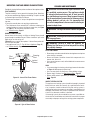
INSPECTING PILOT AND BURNER FLAME PATTERNS
Figure 39 - Correct Pilot Flame Pattern
Figure 40 - Typical Flame Pattern
Pilot
Burner
Igniter/
Sensor
Sensing
Rod
Periodically check pilot flame pattern and burner flame patterns often.
PILOT ASSEMBLY
The pilot assembly is factory preset for the proper flame. Alterations
may have occurred during shipping and handling. The pilot is located
on the back right hand side of the burner.
The flame must envelope 1/4" of top of the igniter/sensor and ground-
ing stem.
If your pilot assembly does not meet these requirements:
• Turn adjustment screw marked PILOT clockwise to decrease or
counterclockwise to increase the flame to proper size (see Figure
37, Page 17). Do not remove adjustment screw.
• see Troubleshooting, Page 21
BURNER FLAME PATTERN
Burner flames will be steady, not lifting or floating. Flames should
go up through the middle of log set. Flames should not "spill" to the
edges of pan or sides of log set.
Figure 40 shows a typical flame pattern. If burner flame pattern dif-
fers from that described:
• turn appliance off (see To Turn Off Gas to Appliance, Page 17)
• see Troubleshooting, Page 21
CLEANING AND MAINTENANCE
WARNING: Installation and repair should be done
by a qualified service person. The appliance should
be inspected before each use and at least annually
by a qualified service person. More frequent cleaning
may be required due to excessive lint from carpeting,
bedding material, pet hair, etc. It is imperative that
the control compartments, burners and circulating air
system be kept clean.
WARNING: Turn off gas and electrical power before
servicing appliance.
WARNING: Failure to keep the primary air
opening(s) of the burner(s) clean may result in sooting
and property damage.
WARNING: The logs can be hot. Handle only when
cool.
PILOT AND BURNER
• Remove logs and ember material before cleaning burner and replace
when cleaning is complete.
• Burner and controls should be cleaned with compressed air to
remove dust, dirt or lint.
• Use a vacuum cleaner or small, soft bristled brush to remove excess
dust, dirt or lint.
LOGS
• If you remove logs for cleaning, refer to log placement information
on Pages 13-14 to properly replace logs.
• Use a vacuum cleaner to remove any carbon buildup on logs.
• Replace log(s) if broken. See Replacement Parts, Page 20.
• Replace ember material periodically as needed. See Replacement
Parts, Page 20.
INSPECT VENTING SYSTEM
The appliance and venting system should be thoroughly inspected
before initial use and at least annually by a qualified service techni-
cian (inspection should include ensuring that venting system is
unobstructed and vent components are properly assembled and not
damaged). Homeowner must contact a qualified service technician
at once if any abnormal condition is observed.
If the venting system is disassembled for any reason, a qualified ser-
vice technician should follow vent installation instructions for proper
reassembly and proper sealing of the venting system components.

SuperiorFireplaces.us.com900807-00E 19
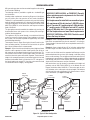
WIRING DIAGRAM
EV2
EV1
MV
P/MV
HIGH VOLTAGE
PV
GND
TH
TR
BLACK
BLACK
BLACK
GAS VALVE
MICRO SWITCH
(IF EQUIPPED)
LIMIT SWITCH
(IF EQUIPPED)
NO NC
PILOT
BURNER
IGNITOR
ORANGE
RED
RED
BLUE
WHITE
BLACK
TRANSFORMER
GROUND
24 VAC
MODULE
IGNITION CONTROL
BLUE
GREEN
120 VAC
IGNITION MODULE
WARNING: Electrical Grounding Instructions - This appliance is equipped with a three-prong
(grounding) plug for your protection against shock hazard and should be plugged directly into a
properly grounded three-prong receptacle. Do not cut or remove the grounding prong from this plug.
Figure 41 - Wiring Diagram
MANUALLY-RESET SAFETY LIMIT SWITCH
This appliance is equipped with a manually-reset blocked flue safety
limit switch. Refer to Figure 42 for its location. If, during appliance
operation, the flame goes out (independently of the burner on/off wall
switch), it may be due to the operation of this safety limit switch. First
allow the appliance to cool, then reset the safety switch by pressing
the red reset button on the back of the switch.
Figure 42 - Blocked Flue Safety Switch, Removal and Reinstallation
Figure 43- Blocked Flue Safety Switch, Red Reset Button
To access the blocked flue safety limit switch, refer to Figure 42:
1. To access the blocked flue safety switch, remove the two (2)
phillips head screws (shown in Figure 42) and pull out switch.
2. Press the red reset button on the switch (see Figure 43).
3. Reinstall switch.
The appliance should then relight and remain lit. If this does not oc-
cur, turn off the appliance and call a qualified service technician.
Blocked Flue Safety
Limit Switch
Red Reset Button
Blocked Flue Safety
Limit Switch
Use Phillips Head Tool

SuperiorFireplaces.us.com 900807-00E20
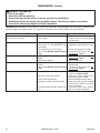
SERVICE HINTS
When Gas Pressure Is Too Low
• pilot will not stay lit
• burner will have delayed ignition
• fireplace will not produce specified heat
• for propane/LP unit, propane/LP gas supply may be low
You may feel your gas pressure is too low. If so, contact your local
gas supplier.
TECHNICAL SERVICE
You may have further questions about installation, operation, or
troubleshooting. Please contact your IHP dealer for any questions
or concerns. When contacting your dealer please have your model
and serial numbers of your fireplace ready. You can also visit our web
site at SuperiorFireplaces.us.com.
REPLACEMENT PARTS
See Pages 23 to 26 for a complete replacement parts list. Use only
parts supplied from the manufacturer.
Normally, all parts should be ordered through your IHP distributor
or dealer. Parts will be shipped at prevailing prices at time of order.
When ordering repair parts, always give the following information:
1. The model number of the fireplace.
2. The serial number of the fireplace.
3. The part number.
4. The description of the part.
5. The quantity required.
6. The installation date of the fireplace.
If you encounter any problems or have any questions concerning the
installation or application of this fireplace, please contact your dealer.
IHP
1769 East Lawrence Street
Russellville, AL 35654
Visit us at SuperiorFireplaces.us.com
Page is loading ...
Page is loading ...
Page is loading ...
Page is loading ...
Page is loading ...
Page is loading ...
Page is loading ...
Page is loading ...
Page is loading ...
Page is loading ...
Page is loading ...
Page is loading ...
-
 1
1
-
 2
2
-
 3
3
-
 4
4
-
 5
5
-
 6
6
-
 7
7
-
 8
8
-
 9
9
-
 10
10
-
 11
11
-
 12
12
-
 13
13
-
 14
14
-
 15
15
-
 16
16
-
 17
17
-
 18
18
-
 19
19
-
 20
20
-
 21
21
-
 22
22
-
 23
23
-
 24
24
-
 25
25
-
 26
26
-
 27
27
-
 28
28
-
 29
29
-
 30
30
-
 31
31
-
 32
32


Superior Fireplaces BRT4000 Operating instructions
- Category
- Stoves
- Type
- Operating instructions
- This manual is also suitable for
Ask a question and I''ll find the answer in the document
Finding information in a document is now easier with AI
Related papers
-
Superior Fireplaces Mossy Oak Outdoor Operating instructions
-
-
-
-
-
-
-
-
-
Other documents
-
Astria Fireplaces WRE30 Instruction Sheet
-
-
Heat & Glo 4000INC Installation guide
-
-
-
 Heatmaster H-SS Installation guide
-
FMI BTC-8 Operating instructions
-
-
Outdoor Lifestyles Mezmer Installation guide
-
HEARTH HOME MZMR-18 Operating instructions
