MacDon D50 & D60 User manual
- Category
- Power universal cutters
- Type
- User manual

D50 and D60 Harvest Headers
®
For Self-Propelled Windrowers
OPERATOR’S MANUAL
Revision
B
Part #169441 $15

This Manual contains instructions for “SAFETY”, “OPERATION”, and “MAINTENANCE/SERVICE” information for your
new MacDon Models D50 and D60 Harvest Header
®
for self-propelled windrowers.
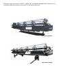
D50 HARVEST HEADER
®
D60 HARVEST HEADER
®

Form 169441 1 Revision B
1 INTRODUCTION
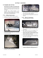
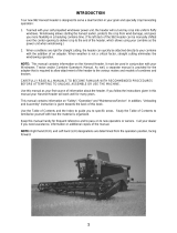
This instructional manual contains operating and maintenance information on the MacDon D50/D60 Harvest
Headers. They are designed to serve a dual function in your grain, hay, and specialty crop harvesting operation.
Teamed with your self-propelled windrower power unit and optional hay conditioner, the D50 and D60 Harvest
Headers will cut and lay crop into uniform fluffy windrows.
Windrowing allows starting the harvest earlier, protects the cop from wind damage, and gives you more flexibility in
scheduling combine time.
CAREFULLY READ ALL THE MATERIAL PROVIDED BEFORE ATTEMPTING TO UNLOAD, ASSEMBLE, OR
USE THE MACHINE.
Use this manual as your first source of information about the machine. If you follow the instructions given here, your
Header will work well for many years.
If you require more detailed service information, a Service Manual is available from your MacDon Dealer.
Use the Table of Contents and the Index to guide you to specific areas. Study the Table of Contents to familiarize
yourself with how the material is organized.
This manual must be used in conjunction with your Self-Propelled Windrower Operator's Manual.
Keep this manual handy for frequent reference and to pass on to new Operators or Owners.
A storage case for this manual is located inside the header left endshield.
Call your MacDon Dealer if you need assistance, information, or additional copies of this manual.
Published: October 2010

Form 169441 2 Revision B
2 MODEL AND SERIAL NUMBER
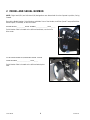
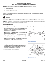
NOTE: Right hand (RH) and Left-hand (LH) designations are determined from the Operator’s position, facing
forward.
Record the Model Number, Serial Number and Model Year of the Header, and Slow Speed Transport/Stabilizer
Wheel Option (if installed), on the lines below:
HEADER MODEL___________SERIAL NUMBER________________YEAR______
Serial Number Plate is located on the left hand endsheet, near the knife
drive motor.
SLOW SPEED TRANSPORT/STABILIZER WHEEL OPTION
SERIAL NUMBER__________________YEAR______
Serial Number Plate is located on the left hand wheel pivot
tube.

TABLE OF CONTENTS
Form 169441 3 Revision B
1
INTRODUCTION ............................................................................................................................................ 1
2 MODEL AND SERIAL NUMBER ................................................................................................................... 2
3 SAFETY ......................................................................................................................................................... 6
3.1 SAFETY ALERT SYMBOL .................................................................................................................... 6
3.2 SIGNAL WORDS .................................................................................................................................. 6
3.3 SAFETY SIGNS .................................................................................................................................... 6
3.3.1 Safety Sign Installation ................................................................................................................. 6
3.3.2 Safety Sign Locations ................................................................................................................... 7
3.4 GENERAL SAFETY ............................................................................................................................ 16
4 DEFINITIONS ............................................................................................................................................... 18
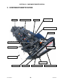
5 COMPONENT IDENTIFICATION ................................................................................................................ 19
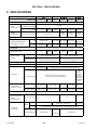
6 SPECIFICATIONS ....................................................................................................................................... 20
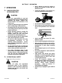
7 OPERATION ................................................................................................................................................ 22
7.1 OWNER/OPERATOR RESPONSIBILITIES ....................................................................................... 22
7.2 OPERATIONAL SAFETY .................................................................................................................... 22
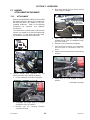
7.3 HEADER ATTACHMENT/DETACHMENT ......................................................................................... 23
7.3.1 Attachment .................................................................................................................................. 23
7.3.2 Detachment ................................................................................................................................. 24
7.4 BREAK-IN PERIOD ............................................................................................................................ 26
7.5 PRE-SEASON CHECK ....................................................................................................................... 26
7.6 DAILY START-UP CHECK ................................................................................................................. 27
7.7 SHUTDOWN PROCEDURE ............................................................................................................... 27
7.8 HEADER CONTROLS ........................................................................................................................ 28
7.9 HEADER LIFT CYLINDER LOCK-OUTS ........................................................................................... 28
7.10 REEL PROPS ..................................................................................................................................... 29
7.11 HEADER SET-UP ............................................................................................................................... 30
7.12 HEADER OPERATING VARIABLES .................................................................................................. 34
7.12.1 Cutting Height ............................................................................................................................. 34
7.12.2 Header Float ............................................................................................................................... 36
7.12.3 Header Angle .............................................................................................................................. 37
7.12.4 Reel Speed ................................................................................................................................. 38
7.12.5 Ground Speed ............................................................................................................................. 39
7.12.6 Draper Speed .............................................................................................................................. 40
7.12.7 Knife Speed ................................................................................................................................. 40
7.12.8 Reel Height ................................................................................................................................. 43
7.12.9 Reel Fore-Aft Position ................................................................................................................. 43
7.12.10 Reel Tine Pitch ............................................................................................................................ 48
7.12.11 Crop Dividers and Rods .............................................................................................................. 50
7.13 DELIVERY OPENING/DECK SHIFT .................................................................................................. 53
7.13.1 Delivery Opening - D60 ............................................................................................................... 53
7.13.2 Delivery Opening - D50 ............................................................................................................... 54
7.14 DOUBLE WINDROWING .................................................................................................................... 55
7.14.1 Hydraulic Deck Shift .................................................................................................................... 55
7.14.2 Manual Deck Shift ....................................................................................................................... 55
7.15 WINDROW TYPES ............................................................................................................................. 57
7.16 HAYING TIPS ...................................................................................................................................... 58
7.16.1 Curing .......................................................................................................................................... 58
7.16.2 Topsoil Moisture .......................................................................................................................... 58
7.16.3 Weather And Topography ........................................................................................................... 58
7.16.4 Windrow Configuration ................................................................................................................ 58
7.16.5 Driving on Windrow ..................................................................................................................... 58
7.16.6 Raking And Tedding.................................................................................................................... 58
7.16.7 Chemical Drying Agents ............................................................................................................. 59
7.17 DRAPER DEFLECTORS .................................................................................................................... 60
7.17.1 Deflector Replacement ............................................................................................................... 60

TABLE OF CONTENTS
Form 169441 4 Revision B
7.17.2 Deflector Rework ......................................................................................................................... 60
7.18 HEADER LEVELLING ......................................................................................................................... 61
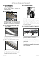
7.19 UNPLUGGING CUTTERBAR ............................................................................................................. 61
7.20 UPPER CROSS AUGER ..................................................................................................................... 62
7.21 TRANSPORTING HEADER ................................................................................................................ 63
7.21.1 On The Windrower ...................................................................................................................... 63
7.21.2 Towing ......................................................................................................................................... 63
7.21.3 Converting from Transport to Field Position ................................................................................ 64
7.21.4 Converting from Field to Transport Position ................................................................................ 69
7.22 STORAGE ........................................................................................................................................... 71
8 MAINTENANCE AND SERVICING .............................................................................................................. 72
8.1 PREPARATION FOR SERVICING ..................................................................................................... 72
8.2 RECOMMENDED SAFETY PROCEDURES ...................................................................................... 72
8.3 MAINTENANCE SPECIFICATIONS ................................................................................................... 73
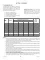
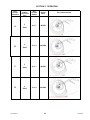
8.3.1 Recommended Torques .............................................................................................................. 73
8.3.2 Roller Chain Installation............................................................................................................... 75
8.3.3 Sealed Bearing Installation .......................................................................................................... 75
8.3.4 Recommended Fluids and Lubricants ......................................................................................... 76
8.3.5 Conversion Chart ......................................................................................................................... 76
8.4 ENDSHIELDS ...................................................................................................................................... 77
8.4.1 Hinged ......................................................................................................................................... 77
8.4.2 Non-Hinged ................................................................................................................................. 79
8.5 LUBRICATION ..................................................................................................................................... 80
8.5.1 Greasing Procedure .................................................................................................................... 80
8.5.2 Lubrication Points ........................................................................................................................ 80
8.5.3 Oiling Requirements .................................................................................................................... 86
8.5.4 Hoses and Lines .......................................................................................................................... 87
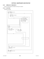
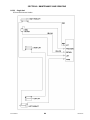
8.5.5 Hydraulic Schematics .................................................................................................................. 88
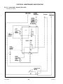
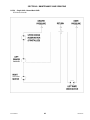
8.6 ELECTRICAL ....................................................................................................................................... 92
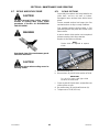
8.7 SICKLE AND SICKLE DRIVE ............................................................................................................. 93
8.7.1 Sickle Sections ............................................................................................................................ 93
8.7.2 Sickle Removal ............................................................................................................................ 94
8.7.3 Sickle Head Bearing Replacement .............................................................................................. 94
8.7.4 Sickle Installation ......................................................................................................................... 95
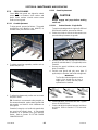
8.7.5 Spare Sickle (Single Knife Headers) ........................................................................................... 95
8.7.6 Sickle Guards .............................................................................................................................. 96
8.7.7 Sickle Hold-Downs ...................................................................................................................... 99
8.7.8 Sickle Drive Belts - Non-Timed Drive ........................................................................................ 100
8.7.9 Sickle Drive Belts - Timed Drive ................................................................................................ 101
8.7.10 Wobble Box ............................................................................................................................... 106
8.8 DRAPERS ......................................................................................................................................... 109
8.8.1 Draper Tension Adjustment ....................................................................................................... 109
8.8.2 Replacing Split Draper ............................................................................................................... 110
8.8.3 Replacing Endless Draper ......................................................................................................... 111
8.8.4 Draper Alignment ....................................................................................................................... 113
8.8.5 Draper Roller Maintenance ....................................................................................................... 114
8.8.6 Deck Height ............................................................................................................................... 117
8.9 REEL AND REEL DRIVE .................................................................................................................. 118
8.9.1 Reel Clearance to Cutterbar ...................................................................................................... 118
8.9.2 Reel Frown Adjustment ............................................................................................................. 119
8.9.3 Reel Centering ........................................................................................................................... 120
8.9.4 Reel Drive Chain - D60.............................................................................................................. 121
8.9.5 Reel Drive Chain - D50.............................................................................................................. 125
8.9.6 Reel Drive Sprocket - D60 ......................................................................................................... 126
8.9.7 Reel Drive Sprocket - D50 ......................................................................................................... 127
8.9.8 Reel Drive U-Joint - D60............................................................................................................ 128
8.9.9 Reel Drive Motor - D60 .............................................................................................................. 129
8.9.10 Reel Drive Motor - D50 .............................................................................................................. 130

TABLE OF CONTENTS
Form 169441 5 Revision B
8.9.11 Reel Speed Sensor ................................................................................................................... 131
8.9.12 Reel Tines ................................................................................................................................. 132
8.9.13 Tine Tube Bushings .................................................................................................................. 134
8.10 TRANSPORT SYSTEM .................................................................................................................... 138
8.10.1 Wheel Bolt Torque .................................................................................................................... 138
8.10.2 Axle Bolts .................................................................................................................................. 138
8.10.3 Tire Inflation .............................................................................................................................. 138
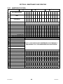
8.11 MAINTENANCE SCHEDULE ........................................................................................................... 139
8.11.1 Break-In Inspections ................................................................................................................. 139
8.11.2 Interval Maintenance ................................................................................................................. 140
8.11.3 Maintenance Record ................................................................................................................. 141
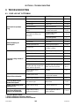
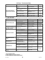
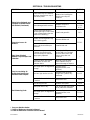
9 TROUBLESHOOTING ............................................................................................................................... 142
9.1 CROP LOSS AT CUTTERBAR ......................................................................................................... 142
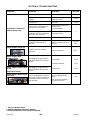
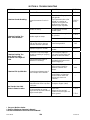
9.2 CUTTING ACTION AND SICKLE COMPONENTS .......................................................................... 143
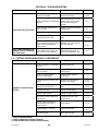
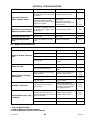
9.3 REEL DELIVERY .............................................................................................................................. 145
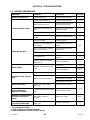
9.4 HEADER AND DRAPERS ................................................................................................................ 147
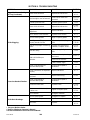
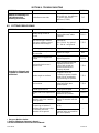
9.5 CUTTING EDIBLE BEANS ............................................................................................................... 148
9.6 WINDROW FORMATION ................................................................................................................. 151
10 OPTIONS AND ATTACHMENTS .............................................................................................................. 152
10.1 CUTTERBAR POLY .......................................................................................................................... 152
10.2 ADJUSTABLE SKID SHOES WITH POLY COVER ......................................................................... 152
10.3 STUB GUARD CONVERSION KIT ................................................................................................... 152
10.4 STABILIZER WHEELS ..................................................................................................................... 152
10.5 STABILIZER/TRANSPORT WHEELS .............................................................................................. 152
10.6 LODGED CROP REEL FINGER KIT ................................................................................................ 153
10.7 VERTICAL KNIFE MOUNTS ............................................................................................................ 153
10.8 UPPER CROSS AUGER KIT ............................................................................................................ 153
10.9 REEL ENDSHIELD KIT ..................................................................................................................... 153
10.10 DOUBLE DRAPER DRIVE ............................................................................................................... 153
10.11 DRAPER EXTENSION KIT ............................................................................................................... 154
10.12 RICE DIVIDER KIT ........................................................................................................................... 154
10.13 KNIFE HEAD SHIELD ....................................................................................................................... 154
10.14 SWATH FORMING RODS ................................................................................................................ 154
10.15 HYDRAULIC DECK SHIFT ............................................................................................................... 154
10.16 DOUBLE WINDROW ATTACHMENT .............................................................................................. 154
10.17 HAY CONDITIONER ......................................................................................................................... 155
10.18 ROCK RETARDER KIT .................................................................................................................... 155
10.19 HYDRAULIC REEL FORE-AFT POSITIONER ................................................................................. 155
11 UNLOADING AND ASSEMBLY ................................................................................................................ 156
INDEX ................................................................................................................................................................ .157

SECTION 3. SAFETY
Form 169441 6 Revision B
3 SAFETY
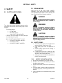
3.1 SAFETY ALERT SYMBOL
This safety alert symbol indicates important safety
messages in this manual and on safety signs on the
machine.
This symbol means:
• ATTENTION!
• BECOME ALERT!
• YOUR SAFETY IS INVOLVED!
Carefully read and follow the safety message
accompanying this symbol.
WHY IS SAFETY IMPORTANT TO YOU?
• ACCIDENTS DISABLE AND KILL.
• ACCIDENTS COST.
• ACCIDENTS CAN BE AVOIDED.
3.2 SIGNAL WORDS
Note the use of the signal words DANGER,
WARNING, and CAUTION with safety messages.
The appropriate signal word for each message has
been selected using the following guidelines:
DANGER
Indicates an imminently hazardous situation
that if not avoided, will result in death or
serious injury.
WARNING
Indicates a potentially hazardous situation
that if not avoided, could result in death or
serious injury. It is also used to alert against
unsafe practices.
CAUTION
Indicates a potentially hazardous situation
that if not avoided, may result in minor or
moderate injury. It is also used as a reminder
of good safety practices.
3.3 SAFETY SIGNS
• The safety signs appear on the header at the
locations shown in the Section 3.3.2.
• Keep safety signs clean and legible at all
times.
• Replace safety signs that are missing or
become illegible.
• If original parts on which a safety sign was
installed are replaced, be sure the repair part
also bears the current safety sign.
• Safety signs are available from your MacDon
Dealer Parts Department.
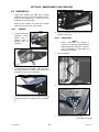
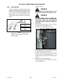
3.3.1 SAFETY SIGN INSTALLATION
a. Be sure the installation area is clean and dry.
b. Decide on the exact location before you remove
the decal backing paper.
c. Remove the smaller portion of the split backing
paper.
d. Place the decal in position and slowly peel back
the remaining paper, smoothing the decal as it is
applied.
e. Small air pockets can be smoothed out or pricked
with a pin.

SECTION 3. SAFETY
Form 169441 7 Revision B
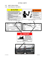
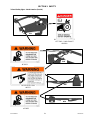
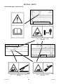
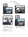
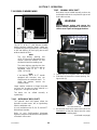
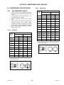
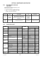
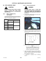
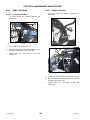
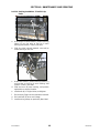
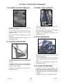
3.3.2 SAFETY SIGN LOCATIONS
3.3.2.1 3-Panel Safety Signs - North America
D60 15 FT
D60 20 FT
BACK TUBE #134070
BACK TUBE & DECKS - BOTH ENDS #172147
A
LL
BACK TUBE - BOTH ENDS #109843

SECTION 3. SAFETY
Form 169441 8 Revision B
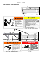
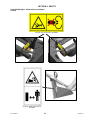
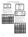
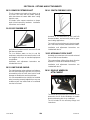
3-Panel Safety Signs - North America (Cont’d)
D50, D60 - 30, 35, 40 FT
D60 25 FT
BACK TUBE BOTH ENDS
#172147
BACK TUBE #134070
BACK TUBE - DOUBLE REEL ONLY
#42122
D50, D60 - 25, 30, 35, 40, FT
BACK TUBE - BOTH ENDS #109843

SECTION 3. SAFETY
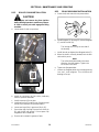
Form 169441 9 Revision B
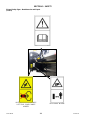
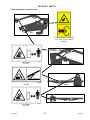
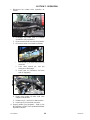
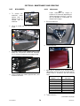
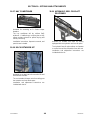
3-Panel Safety Signs - North America (Cont’d)
ALL
D60
BOTH ENDS - DOUBLE KNIFE
LEFT END - SINGLE KNIFE
#142909
LH & RH REEL ARM
#42122
D50
D50
REEL ARMS
#174633
LH & RH REEL ARMS
#174633

SECTION 3. SAFETY
Form 169441 10 Revision B
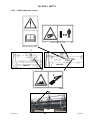
3.3.2.2 2-Panel Safety Signs - North America
and Export
TOW-BAR
#193113
FRONT TRANSPORT LEG
#193147
TOW-BAR
#129261
D50/D60 - 25, 30, 35 FT, D60 - 40 FT

SECTION 3. SAFETY
Form 169441 11 Revision B
2-Panel Safety Signs - North America and Export
(Cont’d)
UPPER CROSS AUGER #174682
LH & RH VERTICAL KNIFE
#174684

SECTION 3. SAFETY
Form 169441 12 Revision B
2-Panel Safety Signs - North America and Export
(Cont’d)
BOTH ENDS #113482
BOTH ENDS - DOUBLE KNIFE
LEFT END - SINGLE KNIFE
#184371
BOTH ENDS #174436

SECTION 3. SAFETY
Form 169441 13 Revision B
3.3.2.3 2-Panel Safety Signs - Export
D60 20 FT
D60 15 FT
ALL
BACKTUBE #174474
BACKTUBE & DECKS #174434
BOTH ENDS #113482

SECTION 3. SAFETY
Form 169441 14 Revision B
2-Panel Safety Signs – Export (Cont’d)
D50, D60 - 30, 35, 40 FT
D60 25 FT
BACK TUBE - BOTH ENDS
#174434
BACK TUBE - DOUBLE REEL ONLY
#174432
BACK TUBE - BOTH ENDS
#174474
D50, D60 - 25, 30, 35, 40 FT
BOTH ENDS #113482

SECTION 3. SAFETY
Form 169441 15 Revision B
2-Panel Safety Signs - Export (Cont’d)
ALL
D60
D50
D50
BOTH ENDS - DOUBLE KNIFE
LEFT END - SINGLE KNIFE
#184371
REEL ARMS
#174632
LH & RH REEL ARM
#174432
REEL ARMS
#174632

SECTION 3. SAFETY
Form 169441 16 Revision B
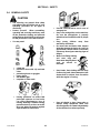
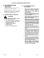
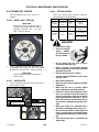
3.4 GENERAL SAFETY
CAUTION
• The following are general farm safety
precautions that should be part of your
operating procedure for all types of
machinery.
• Protect yourself. When assembling,
operating and servicing machinery, wear
all the protective clothing and personal
safety devices that COULD be necessary
for the job at hand. Don't take chances.
• You may need:
• a hard hat.
• protective shoes with slip resistant
soles.
• protective glasses or goggles.
• heavy gloves.
• wet weather gear.
• respirator or filter mask.
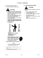
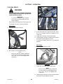
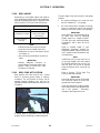
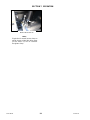
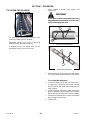
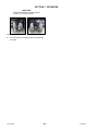
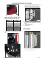
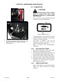
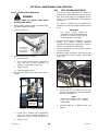
• hearing protection. Be aware that
prolonged exposure to loud noise
can cause impairment or loss of
hearing. Wearing a suitable hearing
protective device such as ear muffs
(A) or ear plugs (B) protects against
objectionable or loud noises.
• Provide a first-aid kit for use in case of
emergencies.
• Keep a fire extinguisher on the machine.
Be sure the extinguisher is properly
maintained and be familiar with its proper
use.
• Keep young children away from
machinery at all times.
• Be aware that accidents often happen
when the Operator is tired or in a hurry to
get finished. Take the time to consider the
safest way. Never ignore warning signs of
fatigue.
• Wear close-fitting clothing
and cover long hair.
Never wear dangling items
such as scarves or
bracelets.
• Keep hands, feet, clothing and hair away
from moving parts. Never attempt to clear
obstructions or objects from a machine
while the engine is running.
• Keep all shields in place. Never alter or
remove safety equipment. Make sure
driveline guards can rotate independently
of the shaft and can telescope freely.
A
B

SECTION 3. SAFETY
Form 169441 17 Revision B
• Use only service and repair parts made or
approved by the equipment manufacturer.
Substituted parts may not meet strength,
design, or safety requirements.
• Do not modify the machine. Unauthorized
modifications may impair the function
and/or safety and affect machine life.
• Stop engine, and remove key from
ignition before leaving Operator's seat for
any reason. A child or even a pet could
engage an idling machine.
• Keep the area used for servicing
machinery clean and dry. Wet or oily
floors are slippery. Wet spots can be
dangerous when working with electrical
equipment. Be sure all electrical outlets
and tools are properly grounded.
• Use adequate light for the job at hand.
• Keep machinery clean. Straw and chaff on
a hot engine are a fire hazard. Do not
allow oil or grease to accumulate on
service platforms, ladders or controls.
Clean machines before storage.
• Never use gasoline, naphtha or any
volatile material for cleaning purposes.
These materials may be toxic and/or
flammable.
• When storing machinery, cover sharp or
extending components to prevent injury
from accidental contact.

SECTION 4. DEFINITIONS
Form 169441 18 Revision B
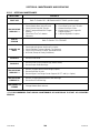
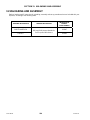
4 DEFINITIONS
TERM DEFINITION
API American Petroleum Institute
ASTM American Society of Testing And Materials
Cab-Forward Windrower operation with the operator and cab facing in the direction of travel
CDM Cab Display Module
DWA Double Windrow Attachment
Engine-Forward Windrower operation with the Operator and engine facing in the direction of travel
ISC Integrated Speed Control
N-DETENT The slot opposite the neutral position on operator’s console
rpm Revolutions per minute
SAE Society Of Automotive Engineers
WCM Windrower Control Module
Windrower Windrower with header attached
Windrower Tractor Power unit only. (Windrower without the header attached)
Page is loading ...
Page is loading ...
Page is loading ...
Page is loading ...
Page is loading ...
Page is loading ...
Page is loading ...
Page is loading ...
Page is loading ...
Page is loading ...
Page is loading ...
Page is loading ...
Page is loading ...
Page is loading ...
Page is loading ...
Page is loading ...
Page is loading ...
Page is loading ...
Page is loading ...
Page is loading ...
Page is loading ...
Page is loading ...
Page is loading ...
Page is loading ...
Page is loading ...
Page is loading ...
Page is loading ...
Page is loading ...
Page is loading ...
Page is loading ...
Page is loading ...
Page is loading ...
Page is loading ...
Page is loading ...
Page is loading ...
Page is loading ...
Page is loading ...
Page is loading ...
Page is loading ...
Page is loading ...
Page is loading ...
Page is loading ...
Page is loading ...
Page is loading ...
Page is loading ...
Page is loading ...
Page is loading ...
Page is loading ...
Page is loading ...
Page is loading ...
Page is loading ...
Page is loading ...
Page is loading ...
Page is loading ...
Page is loading ...
Page is loading ...
Page is loading ...
Page is loading ...
Page is loading ...
Page is loading ...
Page is loading ...
Page is loading ...
Page is loading ...
Page is loading ...
Page is loading ...
Page is loading ...
Page is loading ...
Page is loading ...
Page is loading ...
Page is loading ...
Page is loading ...
Page is loading ...
Page is loading ...
Page is loading ...
Page is loading ...
Page is loading ...
Page is loading ...
Page is loading ...
Page is loading ...
Page is loading ...
Page is loading ...
Page is loading ...
Page is loading ...
Page is loading ...
Page is loading ...
Page is loading ...
Page is loading ...
Page is loading ...
Page is loading ...
Page is loading ...
Page is loading ...
Page is loading ...
Page is loading ...
Page is loading ...
Page is loading ...
Page is loading ...
Page is loading ...
Page is loading ...
Page is loading ...
Page is loading ...
Page is loading ...
Page is loading ...
Page is loading ...
Page is loading ...
Page is loading ...
Page is loading ...
Page is loading ...
Page is loading ...
Page is loading ...
Page is loading ...
Page is loading ...
Page is loading ...
Page is loading ...
Page is loading ...
Page is loading ...
Page is loading ...
Page is loading ...
Page is loading ...
Page is loading ...
Page is loading ...
Page is loading ...
Page is loading ...
Page is loading ...
Page is loading ...
Page is loading ...
Page is loading ...
Page is loading ...
Page is loading ...
Page is loading ...
Page is loading ...
Page is loading ...
Page is loading ...
Page is loading ...
Page is loading ...
Page is loading ...
Page is loading ...
Page is loading ...
Page is loading ...
Page is loading ...
Page is loading ...
-
 1
1
-
 2
2
-
 3
3
-
 4
4
-
 5
5
-
 6
6
-
 7
7
-
 8
8
-
 9
9
-
 10
10
-
 11
11
-
 12
12
-
 13
13
-
 14
14
-
 15
15
-
 16
16
-
 17
17
-
 18
18
-
 19
19
-
 20
20
-
 21
21
-
 22
22
-
 23
23
-
 24
24
-
 25
25
-
 26
26
-
 27
27
-
 28
28
-
 29
29
-
 30
30
-
 31
31
-
 32
32
-
 33
33
-
 34
34
-
 35
35
-
 36
36
-
 37
37
-
 38
38
-
 39
39
-
 40
40
-
 41
41
-
 42
42
-
 43
43
-
 44
44
-
 45
45
-
 46
46
-
 47
47
-
 48
48
-
 49
49
-
 50
50
-
 51
51
-
 52
52
-
 53
53
-
 54
54
-
 55
55
-
 56
56
-
 57
57
-
 58
58
-
 59
59
-
 60
60
-
 61
61
-
 62
62
-
 63
63
-
 64
64
-
 65
65
-
 66
66
-
 67
67
-
 68
68
-
 69
69
-
 70
70
-
 71
71
-
 72
72
-
 73
73
-
 74
74
-
 75
75
-
 76
76
-
 77
77
-
 78
78
-
 79
79
-
 80
80
-
 81
81
-
 82
82
-
 83
83
-
 84
84
-
 85
85
-
 86
86
-
 87
87
-
 88
88
-
 89
89
-
 90
90
-
 91
91
-
 92
92
-
 93
93
-
 94
94
-
 95
95
-
 96
96
-
 97
97
-
 98
98
-
 99
99
-
 100
100
-
 101
101
-
 102
102
-
 103
103
-
 104
104
-
 105
105
-
 106
106
-
 107
107
-
 108
108
-
 109
109
-
 110
110
-
 111
111
-
 112
112
-
 113
113
-
 114
114
-
 115
115
-
 116
116
-
 117
117
-
 118
118
-
 119
119
-
 120
120
-
 121
121
-
 122
122
-
 123
123
-
 124
124
-
 125
125
-
 126
126
-
 127
127
-
 128
128
-
 129
129
-
 130
130
-
 131
131
-
 132
132
-
 133
133
-
 134
134
-
 135
135
-
 136
136
-
 137
137
-
 138
138
-
 139
139
-
 140
140
-
 141
141
-
 142
142
-
 143
143
-
 144
144
-
 145
145
-
 146
146
-
 147
147
-
 148
148
-
 149
149
-
 150
150
-
 151
151
-
 152
152
-
 153
153
-
 154
154
-
 155
155
-
 156
156
-
 157
157
-
 158
158
-
 159
159
-
 160
160


MacDon D50 & D60 User manual
- Category
- Power universal cutters
- Type
- User manual
Ask a question and I''ll find the answer in the document
Finding information in a document is now easier with AI
Related papers
-
 MacDon 962 Harvest User manual
-
 MacDon 963 Harvest User manual
-
 MacDon MD #214165 A D1XL Installation guide
-
 MacDon 973 Harvest User manual
-
 MacDon D65 User manual
-
 MacDon 972 Harvest User manual
-
 MacDon 960 Double and Triple Delivery Harvest User manual
-
 MacDon D1 Quick Card
-
 MacDon 871 User manual
-
 MacDon D50/D60 Unloading & Assembly Instruction


Other documents
-
Draper Rollers and Bearings Stand Operating instructions
-
-
 POWER SOCCER SHOP PN 1525 User manual
-
WEG W22 - Three-phase Motor Exploded View Quick start guide
-
Simplicity 193 User manual
-
 Mi-T-M Hose Reel Owner's manual
-
 Rugged Ridge 11504.11 Installation guide
-
Snapper 1600197 User manual
-
 RoomDividersNow BKTR-90 Installation guide
-
 Land Pride SR2690 User manual


