Page is loading ...

Swiveling, Tilting, Rotating
Flat Panel Wall Mount
Installation Guide
Model: EXTA7032
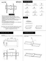
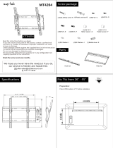
This product Wall Mount frame is intended for use only with an apparatus which has a maximum weight of 77 lbs. See apparatus
instructions. Using with an apparatus heavier than the maximum weight indicated may result in instability and cause possible
injury.
READ THIS FIRST Read this entire manual! Do not attempt to install this product if you do not understand the instructions.
Contact a qualified mount installer if you have any doubts about a safe and secure mount installation, or if you are not sure what
specific wall materials you are attaching this mount to. Check all the parts carefully to make sure there are no missing or
damaged parts. Improper installation may result in damage to your TV, property, and personal injury.
• Supports most 32” - 70” Televisions
• Maximum weight capacity: 77 lbs.
• Supports VESA Sizes up to 600x400
• Easy installation
• Tilt range: +5 to -15 degrees
• Swivel range: 180 degrees
• Extension range: 3.1” to 15.8”
• Rotation range: +5 to -5 degrees
For technical assistance or troubleshooting please call
1-855-994-3832 or visit www.sibrandssupport.com

This product is intended only to mount a television of the indicated size and weight. Using this
product to mount televisions heavier than the maximum weight capacity can damage equip-
ment and cause personal injury.
How and where you use your television wall mount is extremely important for Child Safety
As you set up and use your new product, keep all of these safety tips in mind.
• One size of TV wall mount does not fit all TVs. Use only a TV wall mount rated for the weight
of your TV and the size of your screen. Your TV wall mount assembly instructions contains
specific information on the maximum weight and screen size combination that your wall
mount can safely support. Do not exceed the maximum weight of screen size for any TV wall
mount.
• Carefully read all of enclosed instructions for proper use of this product. If you have any
doubts about safe and secure assembly, please contact a professional.
• Don’t let children climb on or play with mounts or TVs.
• Remember that children can become excited while watching a program, especially on a
“larger than life” TV. Make sure to place or install the TV wall mount where it cannot be
pushed, pulled on, or knocked down.
• Make sure that you route all cords and cables so that they cannot be pulled or grabbed by
curious children.
Always wear safety goggles to when drilling or installing hardware.
Tools
For your convenience, we have included an allen wrench and a socket tool with this mount. For the
best assembly experience and mounting safety, we always recommend using full-size tools for
each assembly steps.
Below is a recommended tool list you will need for proper and safe installation. See applicable
warnings in this manual about certain types of mounting surface materials and the special hard-
ware and tools that should be used.
• Drill with a specific size drill bit to pre-drill holes in the wall
• Stud finder
• Tape measure
• Pencil
• Screw drivers
• Socket wrenches
• Small hammer
• Safety goggles

L
M4x12mm bolts
M5x12mm bolts
M6x12mm bolts
M5/M6 spacers
M8 spacers
10mm spacers
2.5mm spacers
M
N
M6 washers
M4/M5 washers
4
4
O
P
Q
M4x30mm bolts
4
M6x35mm bolts
8
R
Allen Wrench
M8x25mm bolts
M5x30mm bolts
E
F
D
G
H
J
I
K
M8x50mm bolts4
4
4
4
1
Wall Plate
2
Brackets
Concrete Anchor
A x4
B x4
C x4
S
M8x35mm bolts
4
4
4
4
4
4
4
4
M8 washers
1
T
1
U Bubble Level

Fig. 1A
Center the Brackets (2) vertically on the rear of the TV. Attach the Brackets (2) to the rear of the TV
using four of the bolts (D-L) with the proper size washers (Q-S) as shown in Fig. 1a.
Do not over tighten.
If the back of the TV is not flat, or if the bolts are too long, it may be necessary to use Spacers (M-P)
as shown in the Fig. 1B. Multiple Spacers can be used with each bolt to reach the proper length.
Fig. 1B
Q-S
D-G
Q-S
H-L
M-P


65
Fig. 3a
2-1/2” (65mm)
Fig. 3b
Fig. 3c
four
.5
four A
C
A
C
Make sure the
Adjustment Handle
is located in the
Upper Right Side
as shown in Fig. 3c

four
four
A C
B
2.5”
65
are level and parallel.
four
Make sure the horizontal holes are no closer than 16”.
2.5” (65mm)
Fig. 3d
Fig. 3e
Step 4: Hang the television display
A
B
C
Make sure the
Adjustment Handle
is located in the
Upper Right Side
as shown in Fig. 3e

1. Lift the Television display with the brackets attached and carefully hook the Brackets (2) over the
top flange of the Wall Plate (1) as shown in (Fig. 4a) and carefully swing the display down so the
lower part of the Brackets (2) fit over the lower bar of the Wall Plate (1) .
8
Figure 4a
2. Tighten the safety screw on the bottom of each Bracket (2)
using a screwdriver. This will secure theTV to the mount arm
on the Wall Plate (1). Fig 4b
Figure 4b

1. To adjust the Tilt Angle of the TV simply loosen the Tilt Adjustment Handle on the side
of the wall mount by slowly turning the handle to release the tension.
2. Once the tension is released adjust the tilt of the TV to your desired setting and re-tighten
the Tilt Adjustment Handle.
Step 5. Adjusting the Tilt
Fig. 5
9
Tilt Adjustment Handle
Tilt
Swivel ±90°
+5
°
-15°
T
Swivel Adjustment Screw
1.
Use the Allen Wrench (T) to loosen the Swivel Adjustment Screw about 1/2 turn.
2.
To adjust the swivel angle, simply grab the sides of the TV with two hands and carefully slide the TV
in the desired direction. When the TV is in the desired position, carefully let go of the TV.
Step 6. Adjusting the Swivel Tension
To adjust how easily the TV Mount can Swivel you may need to loosen the Swivel Adjustment Screw
shown in Fig. 5.
Rotation Adjustment Screws

Step 7. Adjusting the Rotation
1. If necessary, the TV can be rotated from -5° to +5° by adjusting the two screws which connect the
Wall Plate (1) to the TV Plate (2) as shown in Fig. 6.
2. To adjust the rotation, loosen these two screws with the Allen wrench (T) about 1/2 turn each, and
gently slide the TV Plate (2) to the left or right depending on your needs.
3. Once the TV Plate (2) is in the correct position, re-tighten the screws by turning the Allen wrench (T)
clockwise.
Fig. 6
T
T
Rotation Adjustment Screws
1
2

LIMITED SIX-YEAR WALL MOUNT WARRANTY
We warrant this product to you, the original purchaser at the time of purchase printed on a dated store receipt from
an authorized ETEC retailer and for a period of six-years thereafter that our wall mount product and all it’s parts
and components are free of defects in material and workmanship under normal use. This warranty is subject to
the provisions below. ETEC’s sole obligation and the purchaser’s exclusive remedy pursuant to these warranties
are limited to replacement at ETEC’s sole discretion. There are no other warranties except as expressively set
forth below either expressed or implied, including any warranty of merchantability for any particular purpose.
Should you be missing any of the assembly parts or components (screws, pieces, etc.), please contact the
Customer Support Center to secure a replacement. It is not necessary to bring the unit back to the store. When
calling, please reference the parts list found in the Instruction Manual to help us accurately identify the missing
parts and promptly provide replacements.
For technical support, visit our website www.sibrandssupport.com or call the ETEC Technical Support Center for
technical assistance or troubleshooting at 1-855-994-3832, Monday to Saturday, 10:00AM to 7:00PM EST.
This warranty is expressly limited to the replacement of wall mount parts and components described in the parts
list located in the Instruction Manual included with the product.
This warranty applies under conditions of normal use.
This warranty does not cover: any product, which has been subject to damage due to improper assembly or
disassembly, products which were not assembled, installed, used, or maintained in accordance with the product
assembly instructions & warnings, acts of nature, misuse, neglect, accidents, abuse, exposure to elements,
outdoor use, extreme temperature ranges, damage during transit, commercial use, modification of, or to any part
of the product or attachments to the product not approved by ETEC. Also not covered are costs for
assembly/dis-assembly labor, costs incurred in shipping the unit or parts for warranty repair/exchange or any
products purchased from unauthorized ETEC sellers. Under no circumstances shall ETEC, be liable for any loss
(direct, indirect, incidental, foreseen, unforeseen, special or consequential) or for any damage arising out of, or in
connection with, the use of this product. Nor shall ETEC have any responsibility for incidental or consequential
damages resulting from the breach of this warranty including but not limited to inconvenience, purchase or rental
of replacement products, loss of profits or commercial loss.
We reserve the right to request damaged parts or units be shipped to our offices for inspection or confirmation of
any warranty claims.
This warranty does not cover product sold ‘As Is’.
This warranty is valid only to the original purchaser of the Product in the United States and Canada and grants
specific legal rights.

Schoenfeld International Inc and ETEC
5001 American Boulevard West
Suite 275
Bloomington, MN 55437
©Schoenfeld International Inc. 2017
PN: EXTA7032 Rev 1.0 May 2017
/