Page is loading ...

Tilting LCD/Plasma Flat Panel
Wall Mount
Installation Guide
• Supports most 36” - 63” LCD/Plasma Flat Panels
• Maximum weight capacity: 176 lbs.
• Supports VESA Sizes up to 700X500
This product is intended only to mount a television of the indicated size and weight.
Using this product to mount televisions heavier than the maximum weight capacity can
damage equipment and cause personal injury.
READ THIS FIRST
Read this entire manual! Do not attempt to install this product if you do not understand the
instructions. Contact a qualied mount installer if you have any doubts about a safe and
secure mount installation, or if you are not sure what specic wall materials you are at-
taching this mount to. Check all the parts carefully to make sure there are no missing
or damaged parts. Improper installation may result in damage to your TV, property, and
personal injury.
• Easy installation
• Low prole
• Built-in level for easy positioning
• Safety bolts lock the TV on the mount
• Easy to adjust tilt angles:
-5 to 15 degrees
Model: E580TM

This product is intended only to mount a television of the indicated size and weight. Using this
product to mount televisions heavier than the maximum weight capacity can damage equipment
and cause personal injury.
Schoenfeld International Inc. and ETEC USA are not responsible for personal injury or
product damage due to mishandling, incorrect mounting, incorrect assembly, or incorrect use of
this product.
CHILD SAFETY
How and where you use your television wall mount is extremely important for Child Safety
As you set up and use your new product, keep all of these safety tips in mind.
• One size of TV wall mount does not t all TVs. Use only a TV wall mount rated for the weight of
your TV and the size of your screen. Your TV wall mount assembly instructions contains spe-
cic information on the maximum weight and screen size combination that your wall mount can
safely support. Do not exceed the maximum weight of screen size for any TV wall mount.
• Carefully read all of enclosed instructions for proper use of this product. If you have any doubts
about safe and secure assembly, please contact a professional.
• Don’t let children climb on or play with mounts or TVs.
• Remember that children can become excited while watching a program, especially on a “larger
than life” TV. Make sure to place or install the TV wall mount where it cannot be pushed, pulled
on, or knocked down.
• Make sure that you route all cords and cables so that they cannot be pulled or grabbed by curi-
ous children.
Always wear safety goggles to when drilling or installing hardware.
Tools
For your convenience, we have included an allen wrench and a socket tool with this mount. For the best
assembly experience and mounting safety, we always recommend using full-size tools for each assem-
bly steps.
Below is a recommended tool list you will need for proper and safe installation. See applicable warnings
in this manual about certain types of mounting surface materials and the special hardware and tools that
should be used.
• Drill with a specic size drill bit to pre-drill holes in the wall
• Stud nder
• Tape measure
• Pencil
• Screw drivers
• Socket wrenches
• Small hammer
• Safety goggles

3
The actual appearance and quantity of parts may be different than shown in the illustration. Consult
the table for actual quantities.

4
Step 1: Attach the left and right brackets to your TV
Do not force the bolts into the mounting holes on your TV. Do not use an electric drill to tight-
en these bolts on your TV. This could damage the equipment or cause personal injury.
CAUTION: Do not place the TV face down on a hard surface when installing the mounting plate
on the TV. Placing the TV face down on a hard surface can result in equipment damage. Use a
blanket or other suitable surface.
Check your TV manual to conrm the required bolt diameter according to the size, depth, and position
of the mounting holes in your TV.
For correct installation, install the brackets with the hook on each bracket facing down
Install the bolts, spacers, and square washers in accordance with the following:
If your television has a straight back, spacers are not required. Use the selected bolts (A-F) and
square washers (I) to install the bracket directly on the back of the television as shown in Fig 1a. Make
sure that the two brackets are equal in height and are level. Once the brackets are aligned, securely
tighten the bolts..
Fig. 1a

5
If your television has a curved back and mounting
holes are recessed (Fig a), spacers are required.
Install the spacers (M) between the display and
the bracket as shown in Fig 1b. Then use the se-
lected bolts (A-H) and square washers (I) to in-
stall the brackets with spacers to the back of the
television. Make sure that the two brackets are
equal in height and are level. Once the brackets
are aligned, securely tighten the bolts (Fig 1 b).
Fig. a
Fig. 1b
Step 2: Install the cable cover
Route the cables as required. Snap the cable cover into place on
the rods (Fig. 2a), and then slide the cover into position as required
(Fig. 2b).
Slide down
Fig. 2a
Fig. 2b

6
Step 3: Attach the wall mount to the wall
Find and mark the best position for the wall mount on the wall.
The best viewing height is parallel to the eye level of a person sitting on a couch. Normally, this is
about 4 feet above oor level.
In addition to your eye level height when you are seated, the following two measurements will help
you determine the perfect height for your wall-mounted television:
• The distance from your viewing location to the wall.
• The vertical distance from eye level to the oor plus the distance from your viewing location to the
wall when the viewing angle is 15 degrees.
For example:
• If distance ‘a’ is 5 to 7 feet (1.5 to 2.1 meters), distance ‘b’ is about 1 foot (0.3 meter)
• If distance ‘a’ is 8 to 13 feet (2.4 to 4 meters), distance ‘b’ is about 3 feet (0.9 meter)
• If distance ‘a’ is 14 to 17 feet (4.3 to 5.2 meters), distance ‘b’ is about 4 feet (1.2 meters)
Add the eye level height plus ‘b’ to get the ideal height of the center of the television display.
After determining the ideal height on the wall for your television, follow the mounting instructions for
your type of wall construction: wood stud walls or masonry walls (concrete, brick, or stone).
Attaching this mount to steel studs, concrete, or brick walls requires special tools and hard-
ware to ensure the mount is securely and safely attached to these materials. Brick and con-
crete will break or crumble if special masonry drill bits and drill operating speeds are not prop-
erly used. Steel studs will not securely support a mount unless special drill bits and mounting
hardware are used for the installation. Please consult a hardware or mount installation expert
before installing the mount to walls of these materials. Consult a professional if you are un-
sure or have any doubts about the safety of the installation. Personal injury or equipment
damage can result if the mount is not properly installed.
Fig. 3

7
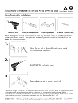
Wood stud walls (Fig 3b)
1. Use a pencil, awl, or a nail to mark the location of the wall stud centers (Fig 3b) after locating the
stud with an electronic stud locator. The distance between marks should not be less than 16 inches
(Studs must not be less than 16 inches (40.6 cm).
2. Place the wall mount at against the wall with the center of the mount in the desired location, align-
ing the holes in the mount with the studs (Fig 3c). Use the wall plate as a template to mark the
location of all four mounting holes on the wall. Make sure that the mounting holes are level and are
parallel.
3. Use a 5 mm drill bit to pre-drill holes at least 40 mm (1.6 inches) deep at the marked locations.
4. Use the supplied box-end wrench (6), the four long bolts (J), and washers (L) to attach the wall
mount to the wall. Do not use wall anchors in wood stud walls.
5. Use the built-in level to level the wall mount (Fig 3d), repositioning as necessary, then securely
tighten the bolts.
Fig. 3b Fig. 3c
Fig. 3d
Masonry Walls (Concrete, Brick, or Stone):
1. Place the wall mount at against the wall in the desired location. Use the wall plate as a template
to mark the location of all four mounting holes on the wall. Make sure that the mounting holes are
level and are parallel.
2. Use a 10 mm drill bit to pre-drill four holes at least 50 mm (2 inches) deep at the marked locations.
3. Insert a wall anchor (K) into each pre-drilled hole and lightly tap it with a hammer until the wall an-
chor is ush with the wall.
4. Use the supplied box-end wrench (6), the four long bolts (J), and washers (L) to attach the wall
mount to the wall with the wall anchors.
5. Use the built-in level to level the wall mount (Fig 3d), repositioning as necessary, then securely
tighten the bolts.
1
L
J
6

8
Step 4: Hang the television display
A large television requires two people to lift. Schoenfeld International Inc. and ETEC USA are
not responsible for equipment damage or personal injury due to mishandling.
Do not release the TV until you are sure that it is securely mounted. Releasing the TV without rst
ensuring that it is securely installed can result in equipment damage or personal injury.
1. Lift the television display with the brackets securely attached to the wall mount.
2. Hook the top of brackets over the top bar of the wall mount (Fig 4a).
3. Rotate the display to let the brackets hook over the bottom bar of the mount. Then install a safety bolt
(5) into the lower end of each bracket to lock the television in place (Fig 4b).
.
Fig. 4a Fig. 4b

9
Fig. 5
Step 5: Adjusting the tilt angle
This patented design features an unique tilt angle mechanism that can easily be adjusted by just one
person. No tools are required for this step. As shown in Fig. 5, grasp the top and bottom of the mounted
at panel and gently pull the top of the at panel toward you or back to adjust the viewing angle.
Mount Reference Dimensions
Adjustable bracket spacing: 200 – 700 mm
(7.87 in – 27.55 in)
Bracket height: 530 mm (20.86 in)
Bracket frame height: 180 mm (7.08 in)
Bracket frame length: 820 mm (32.28 in)

10
LIMITED SIX-YEAR MOUNT WARRANTY
ETEC USA warrants this product to be free from defects in material and workmanship for a six-year period after pur-
chase. We will repair or replace the unit free of charge should it become defective under this warranty.
Should you have any missing or defective assembly hardware (screws, etc.), please contact the retailer to secure a
replacement for those parts. It should not be necessary to bring the entire unit to the store but instead bring the parts list
to accurately identify the missing piece(s) and obtain replacements. Should you prefer, you can contact us by email at
If you need to process a warranty claim for a defective part (not including assembly hardware), you, the original purchas-
er, should submit a copy of the original sales slip along with the model number, part number and a detailed description
of the problem with that part. You may send the required information either via email to [email protected] or, should
you prefer, you may send the information via US mail to:
ETEC USA
823 Old Settlers Trail
Suite 100
Hopkins, Minnesota 55343
Please also include a phone number, for a faster process should we need to contact you for any reason. Failure to attach
or enclose the required information may result in a delay processing your request.
ETEC USA will warrant all mount parts and components described in the parts list of this model. The warranty covers
defective material and workmanship and applies under normal use. Our mounts are not intended for outdoor use.
This warranty does not cover any product, which has been subject to damage due to improper assembly or disassembly,
an act of nature, misuse, neglect, accident, abuse, commercial use, or modication of, or to, any part of the product. Also
not covered are assembly costs, any labor or labor cost incurred for any reason, products purchased from unauthorized
ETEC sellers or costs incurred in shipping the unit or part for warranty repair. Under no circumstances shall ETEC USA,
be liable for any loss (direct, indirect, incidental, foreseen, unforeseen, special or consequential) or for any damage aris-
ing out of, or in connection with, the use of this product.
This warranty does not cover product sold ‘As Is’.
This warranty is void if the mount has been moved from its initial installation location.
This warranty is valid only in the United States and grants specic legal rights.

11

Schoenfeld International Inc and ETEC USA
823 Old Settlers Trail
Suite 100
Hopkins, Minnesota 55343
©Schoenfeld International Inc, 2009
PN: E580TM Rev 1.0 February 2009
/