Page is loading ...

Two Shelf, Wall Mounted
A/V Component Stand
Installation Guide
Model: EX202DS
For technical assistance or troubleshooting
please call 1-855-994-3832.
This product is intended for use only with Audio/Video components (Not for use with any type of TV). The maximum weight
capacity per shelf is 22 lbs. See apparatus instructions. Using with an apparatus heavier than the maximum shelf support
weight indicated may result in instability and cause personal injury.
READ THIS FIRST
Read this entire manual! Do not attempt to install this product if you do not understand the instructions. Contact a qualified
mount installer if you have any doubts about a safe and secure mount installation, or if you are not sure what specific wall
materials you are attaching this mount to. Check all the parts carefully to make sure there are no missing or damaged parts.
Improper installation may result in damage to your Components, TV, property, and personal injury.

This product is intended only to be used to support Audio/Video Components (DVD players,
Cable boxes, 5.1 Sound syste .noisiveleT fo epyt yna rof dnats siht esu ton oD ).cte ,sm
Use with components heavier than the maximum shelf weight capacity can damage equipment and
cause personal injury.
Schoenfeld International Inc. and ETEC are not responsible for personal injury or product
damage due to mishandling, incorrect mounting, incorrect assembly, or incorrect use of this
pr
oduct.
Always wear safety goggles to when drilling or installing hardware.
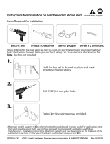
Tools
For your convenience, we have included an allen wrench and a socket tool with this mount. For the best as-
sembly experience and mounting safety, we always recommend using full-size tools for each assembly steps.
Below is a recommended tool list you will need for proper and safe installation. See applicable warnings
in this manual about certain types of mounting surface materials and the special hardware and tools that
should be used.
• Drill with a specific size drill bit to pre-drill holes in the wall
• Stud finder
• Tape measure
• Pencil
• Screw drivers
• Socket wrenches
• Small hammer
• Safety goggles
CHILD SAFETY
How and where you use your A/V Component Wall Mount Stand is extremely important for Child Safety
As you set up and use your new product, keep all of these safety tips in mind.
One size of A/V Component Stand does not support all components weights and sizes.•
Your A/V Component Stand assembly instructions contains specific information on the maximum weight •
capacity per shelf that your A/V Component Sta
nd can safely support. Do not exceed the maximum
support weight for each shelf.
Carefully read all of enclosed instructions for proper use of this product. If you have any doubts about •
safe and secure assembly, please contact a professional.
Don’t let children climb on or play next to Wall Mounted A/V Stands or TV Wall Mounts.•
Remember that children can become excited while watching a program, especially on a “larger than •
life” TV. Make sure to place or install the A/V Component
Stand where it cannot be pushed, pulled on,
or knocked down.
Make sure that you safely route all cords and cables so that they cannot be pulled or grabbed by curious •
children.

*The shelf with the ETEC
logo is the top shelf.
A
x2
B
x2
C
x2
x2
x4
D
E
F
G
H
Wall Plate
Plastic Cover
Shelf Support
Glass Shelves
B
Concrete Anchors
Long Bolt Washers
Shelf Security Bolt
C
Long Bolts
A
D
2
2
2
2
F
Glass Shelf Suction Pads
Cable Management Clips
Allen Wrench
G
E
H
4
8
8
1
M6x8mm Bolts
x8
x8
x1
1 1
2 1
3 2
4 2
Wall Plate
Plastic Cover
Shelf Support
Glass Shelf
3
WasherI 2
I
x2
1
2
x1
3
x2
x24
x1
Long Bolts
Concrete Anchors Long Bolt Washers
Shelf Security Bolts
M6x8mm
Glass Shelf
Suction Pads
Cable Management
Clips
Allen Wrench
with Phillips End
Washer
Bolts
M6x12mm

Do not attach this A/V Component Stand to any wall with Brick or steel stud construction.
Attaching this mount to wood or concrete walls requires special tools and hardware to
ensure the mount is securely and safely attached to these materials. Brick and concrete
will break or crumble if special concrete drill bits and drill operating speeds are not properly
used. Consult a professional if you are unsure or have any doubts
about the safely of the
installation. Personal injury or equipment damage can result if the mount is not properly
installed.
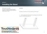
Wood stud walls (Fig 1):
1. Use an electronic stud finder to locate the wall studs. Mark their locations on the wall.
2. Place the Wall Plate (1) flat against the wall in the desired mounting location, aligning the mounting
holes on the bracket with the studs. Use the Wall Plate (1) as a template to mark the mounting holes
on the wall.
3. Use 3/16” (5mm) drill bit to pre-drill holes at least 2.5” inches (65mm) deep at the marked locations.
4. Use the Long Bolts (A) and Long Bolt Washers (C) to mount the Wall Plate (1) to the wall as shown
in Fig. 3. Do not use wall anchors in wood stud walls.
5. Use a level to make sure the Wall Plate (1) is perfectly straight and securely tighten the Long Bolts (A)
using a proper size wrench. Make sure to tighten the top bolt first, then re-check the level before
tightening the bottom bolt.
Step 1: Install the Wall Plate
Read the instructions. Determine the proper location for your wall type. Make sure the mounting location
has enough space for the Glass Shelf (4) and the Wall Plate (1). Follow the mounting instructions for
wood studs or concrete wall installation.
1
A
4
C
2-1/2” (65mm)

A
B
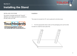
1. Place the Wall Plate (1) flat against the wall in the desired mounting location. Use the Wall Plate (1) as
a template to mark the mounting holes on the wall. Make sure that the mounting holes are level and are
parallel.
3. Insert a Concrete Anchor (B) into each pre-drilled hole and lightly tap it with a hammer until the
Concrete Anchor (B) is flush with the wall.
2. Use a 3/8” (10mm) drill bit to pre-drill two holes at least 2.5” (65mm) deep at the marked locations.
4. Use the Long Bolts (A) and Long Bolt Washers (C) to attach the Wall Plate (1) to the wall with the
Concrete Anchors (B) as shown in Fig. 4.
5. Use a level to make sure the Wall Plate (1) is perfectly straight and securely tighten the Long Bolts (A)
using a proper size wrench. Make sure to tighten the top bolt first, then re-check the level before
tightening the bottom bolt.
Do not use the Concrete Anchors (B) for drywall installation. Use of Concrete Anchors
for drywall installations can result in personal injury or product damage.
5
2.5” (65mm)
C

Step 2: Install the Plastic Cover
Fig. 5
Align the four tabs on the Plastic Cover (2) with the 4 cut-outs on the Wall Plate (1) as shown in Fig. 5.
Gently apply pressure unitil the Plastic Cover (2) snaps into position on the Wall Plate (1).
2
6
Step 3: Install the Glass Shelf Suction Pads
Insert the eight Glass Shelf Suction Pads (F) into the holes on the Shelf Supports (3) as shown in Fig. 6.
F
Fig. 6
3
F
3

Step 4: Install the Shelf Supports
Step 5: Install the Glass Shelf
Carefully place the Glass Shelf (4) on the Shelf Support (3) as shown in Fig. 8.
NOTE: Make sure to align the hole near the rear of the Glass Shelf (4) with the hole in the Shelf
Support (3)
Hole in Shelf
Hole in Shelf Support
Fig. 8
7
Attach the Shelf Supports (3) to the Wall Plate (1) using the four M6x8mm Bolts (E) and Allen
Wrench (H) as shown in Fig. 6. Do not overtighten the bolts.
Fig. 6
E
H
E
H
NOTE: Use the shelf with the ETEC logo in the top position.

Step 6: Secure the Glass Shelf
Secure each Glass Shelf (4) by inserting the Washer (I) and Shelf Security Bolt (D) into the hole in the
Glass Shelf (4) as shown in Fig. 9.
Tighten the Shelf Security Bolt (D) using the Allen Wrench (H). Do not overtighten or the glass shelf
will break.
I
C
Fig. 9
8

Step 7: Using the Cable Management System
9
G
This A/V Component Stand includes a cable management system which allows cables or cords to be
neatly routed along the sides of the Wall Plate (1).
Insert the Cable Management Clips (G) into the holes near the sides on the Plastic Cover (2) as
shown in Fig. 10.
Cables can be routed up or down as there are Cable Management Clip (G) spaces 2" above & 2" below
each shelf to allow for easy cable management.
NOTE: For best system performance, route the AC power cords separately from the signal cables to keep
the power and signal cables from being wrapped around each other.
Once your cables are in place twist the ends of the Cable Mangement Clips (G) to lock the ends of the
clips.
CAUTION: To avoid possible electrical shock, use ONLY your fingers to apply pressure when
inserting cables and power cords into the Cable Management Clips (G). DO NOT use any kind of
tool for this step.

This page is intentionally left blank

LIMITED SIX-YEAR WALL MOUNT WARRANTY
We warrant this product to you, the original purchaser at the time of purchase printed on a dated store receipt from
an authorized ETEC retailer and for a period of six-years thereafter that our wall mount product and all it’s parts
and components are free of defects in material and workmanship under normal use. This warranty is subject to
the provisions below. ETEC’s sole obligation and the purchaser’s exclusive remedy pursuant to these warranties
are limited to replacement at ETEC’s sole discretion. There are no other warranties except as expressively set
forth below either expressed or implied, including any warranty of merchantability for any particular purpose.
Should you be missing any of the assembly parts or components (screws, pieces, etc.), please contact the
Customer Support Center to secure a replacement. It is not necessary to bring the unit back to the store. When
calling, please reference the parts list found in the Instruction Manual to help us accurately identify the missing
parts and promptly provide replacements.
Our Customer Support Center is available Monday to Saturday (10:00AM to 7:00PM EST) for technical assistance
or troubleshooting. To contact us please call 1-855-994-3832.
This warranty is expressly limited to the replacement of wall mount parts and components described in the parts
list located in the Instruction Manual included with the product.
This warranty applies under conditions of normal use.
This warranty does not cover: any product, which has been subject to damage due to improper assembly or
disassembly, products which were not assembled, installed, used, or maintained in accordance with the product
assembly instructions & warnings, acts of nature, misuse, neglect, accidents, abuse, exposure to elements,
outdoor use, extreme temperature ranges, damage during transit, commercial use, modification of, or to any part
of the product or attachments to the product not approved by ETEC. Also not covered are costs for
assembly/dis-assembly labor, costs incurred in shipping the unit or parts for warranty repair/exchange or any
products purchased from unauthorized ETEC sellers. Under no circumstances shall ETEC, be liable for any loss
(direct, indirect, incidental, foreseen, unforeseen, special or consequential) or for any damage arising out of, or in
connection with, the use of this product. Nor shall ETEC have any responsibility for incidental or consequential
damages resulting from the breach of this warranty including but not limited to inconvenience, purchase or rental
of replacement products, loss of profits or commercial loss.
We reserve the right to request damaged parts or units be shipped to our offices for inspection or confirmation of
any warranty claims.
This warranty does not cover product sold ‘As Is’.
This warranty is valid only to the original purchaser of the Product in the United States and Canada and grants
specific legal rights.

PN: EX202DS Rev 1.0 July 2014
©
Schoenfeld International Inc. 2014
Schoenfeld International Inc. and ETEC
5001 American Boulevard West
Suite 275
Bloomington, MN 55437
/