Page is loading ...

[AKD4490-SG]
< KM119704> - 1 - 2016/04
GENERAL DESCRIPTION
The AKD4490-SG is a sound evaluation board for the AK4490EN; AK4490EN is a new generation
Premium 32-bit 2ch DAC. The AKD4490-SG can be applied to the solutions for the smartphone. This
board has digital audio interfaces, enabling to interface to digital audio systems via optical or coaxial
connector. A USB Connection is adopted for control interface.
■ Ordering Guide
AKD4490-SG --- Evaluation board for AK4490EN
Control Software
FUNCTION
Three digital audio interfaces
- Optical Input
- Coaxial Input
- 10-pin Header for External Interface
USB Connector for control interface
A 3.5 mm stereo mini jack connector for analog audio Output
to AK4118A
and Level Shifter
to VDDL/R
and VREFHL/R
R
egulator (
U302
)
[+3.7V
→
+1.8V]
Battery (JP301)
DC
-
DC
(U
301
)
[+3.7V
→
+7V]
[+3.7V
→
-5V]
+7V
-
5V
to AVDD
and DVD
D
Regulator
(U304)
[+7V
→
+5V]
R
egulator (U
303
)
[+3.7V
→
+3.3V]
Audio clock
to TVDD
HP OUT
(J401)
AK4490EN
(U202)
2nd Order LPF
and
Headphone Amp
EXT PORT
(PORT201)
USB
(J501)
PIC18F4550
(U501)
Regulator
(
U503
)
[+5V
→
+3.3V]
AK8157A
(U201)
Serial Control
CLKIN (J201)
Audio data
9.6MHz
to AK8157A
and X201
from Regulator (U302)
+1.8V
X201
9.6MHz
Coax In (J101)
AK4118A
(U101)
Opt In
(PORT101)
from Regulator (U303)
+3.3V
Level Shifter
(U203)
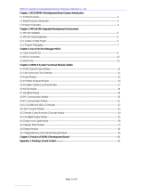
Figure 1. AKD4490-SG Block Diagram (SPDIF input)
AKD4490-SG Evaluation Board Rev.4
AKD4490-SG

[AKD4490-SG]
< KM119704> - 2 - 2016/04
to AK4118A
and Level Shifter
to VDDL/R
and VREFHL/R
R
egulator (
U302
)
[+3.7V
→
+1.8V]
Battery (JP301)
DC
-
DC
(U
301
)
[+3.7V
→
+7V]
[+3.7V
→
-5V]
+7V
-
5V
to AVDD
and DVD
D
Regulator
(U304)
[+7V
→
+5V]
R
egulator (U
303
)
[+3.7V
→
+3.3V]
Audio clock
to TVDD
HP OUT
(J401)
AK4490EN
(U202)
2nd Order LPF
and
Headphone Amp
EXT PORT
(PORT201)
USB
(J501)
PIC18F4550
(U501)
Regulator
(
U503
)
[+5V
→
+3.3V]
AK8157A
(U201)
Serial Control
CLKIN (J201)
Audio data
9.6MHz
to AK8157A
and X201
from Regulator (U302)
+1.8V
X201
9.6MHz
Coax In (J101)
AK4118A
(U101)
Opt In
(PORT101)
from Regulator (U303)
+3.3V
Level Shifter
(U203)
Figure 2. AKD4490-SG Block Diagram (EXT input)

[AKD4490-SG]
< KM119704> - 3 - 2016/04
EVALUATION BORAD
Figure 3. AKD4490-SG Board View
(1) JP301
Battery Header
(2-a)
PORT101
OPT
(2-b) J101
COAX
(4) PORT201
EXT PORT
(5-a) J201
External Clock In
(3) J401
Headphone OUT
(6) AK4118A
(7) AK8157A
(8) AK4490EN
J501
USB
SW201
Power Up / Down
(5-b) X201
Xtal Oscillator

[AKD4490-SG]
< KM119704> - 4 - 2016/04
Component explanation
(1) Battery Header (JP301 / +3.7V, GND)
Refer to (Table 2).
(2) SPDIF input connector (J101 / BNC connector, PORT101 / Optical connector)
SPDIF signal Inputs to the AK4118A.
(a) When using PORT101 (Optical connector), set to R114 = “open” and R112= “0 ohm”.
(b) When using J101 (BNC connector), set to R114 = “0 ohm” and R112 = “open”.
The default setting is (b). Refer to the circuit diagram of Figure 4
Figure 4 . Circuit diagram of SPDIF input.
(3) Headphone Out (J401 / 3.5 mm stereo mini jack)
Connect to headphone
(4) EXT PORT (PORT201)
10 pin header for interfacing with external data sources, enabling to connect other audio systems.
When using PORT201 (EXT), set to R202, R203, R204 = “0 ohm” and R205 = “100 ohm”.
In addition, connect 1pin and 2pin of JP201.
Table 1. Pin Assignment of PORT201(EXT)
Pin I/O Function pin I/O Function
1 I MCLK 2 - GND
3 I BICK 4 - GND
5 I LRCK 6 - GND
7 I SDATA 8 - GND
9 - NC 10 - GND
(5) External Clock In (J201 / BNC connector, X201 / Xtal Oscillater)
Input 9.6MHz clock when outputting audio clocks from AK8157A.
(a) When using J201(BNC connector), set to R201 = “0 ohm” and X201 = “open”.
(b) When using X201(Xtal Oscillater), set to R201 = “open”.
(6) AK4118A (U101)
AK4118A is Digital Audio I/F Transceiver.
When evaluating the sound quality, using AK4118A with SPDIF signal.
(7) AK8157A (U201)
AK8157A is Audio Clock Generator.
This device supplies BICK, LRCK and MCLK to AK4490EN when 9.6Mhz clock inputs.
(8) AK4490EN (U202)
AK4490EN is premium 32-bit 2ch DAC. It is the main device on this board.

[AKD4490-SG]
< KM119704> - 5 - 2016/04
OPERATION SEQUENCE
Set up the power supply lines
Connect the battery to the battery header (JP301).
Table 2. Set up of power supply lines
Name Color Voltage Comments Attention
JP301 White 1pin
+3.7V~+4.2V
Power supply This is always needed. Power line
JP301 White 2pin 0V GND This is always needed.
Toggle SW Function
*Upper-side is “H” and lower-side is “L”.
Figure 5. SW201 Power-up/down switch direction
Power-down reset by SW201 (PDN) must be made once after power up the evaluation board. Put the SW201 to “L”
for power-down reset of the AK4490EN, AK8157A and AK4118A, and the return it to “H” to release the
power-down states.
[SW201] (PDN): Resets the AK4490EN, AK8157A and AK4118A (Keep “H” during normal operation).
This switch must be set to “L” once upon power up the evaluation board to reset the AK4490EN,
AK8157A and AK4118A.
*Caution
When changing from power on (power off) to power off (power on), please remove the headphone from ear. Ear
may be hurt, due to generate the noise.
“
H
”
“L”

[AKD4490-SG]
< KM119704> - 6 - 2016/04
Jumper setting
(1) Using SPDIF signal from optical connecter or coaxial connecter <Default>
JP201 is set as shown in Figure 5 when SPDIF signal from optical connecter or coaxial connecter use.
(2) Using External PCM signal
JP201 is set as shown in Figure 6 when the PCM signal from EXT PORT (Tabel.1) use.
*Default setting is (1).
Figure 6. Jumper setting for SPDIF <Default>
Figure 7. Jumper setting for external PCM
Board Control
The AKD4490-SG should be controlled via a USB port with a PC. Connect J501 (USB) connector to a PC with USB
cable. The control software is included in the AK4490-SG package. Setting System is referred to following Figure 8.
Figure 8. Control System Setting
Audio playback
Connect the headphone or earphone to J401 (3.5mm stereo mini connector), and connect the optical cable to
PORT101 or coaxial cable to J101 from the audio equipment.
The volume can be adjusted by control software.
USB type B Cable

[AKD4490-SG]
< KM119704> - 7 - 2016/04
CONTROL SOFTWARE MANUAL
■ Setup of the Evaluation Board and Control Software
(1). Set an AKD4490-SG properly.
(2). Power supplies to battery header (JP301) for the Power ON of AKD4490-SG.
(3). Connect AKD4490-SG to PC with USB cable.
USB control is recognized as HID (Human Interface Device) on the PC.
When it can‘t be recognized correctly, connect AKD4490-SG to PC with USB cable.
(4). AK4490EN, AK8157A and AK4118A must be reset once bring SW201 “L” to “H”.
* Direction of “H” is referred to Figure 5
(5). Double-click the icon “AKD4490-SG.exe” to open the control program.
When the screen does not display “AKDUSBIF-B” at bottom left, reconnect the PC and the USB cable, and push
the [Port Reset] button.
(6). Begin evaluation by following the procedure below.
Figure 9. Window of Control Soft
(5)
(5)

[AKD4490-SG]
< KM119704> - 8 - 2016/04
Operation Overview
Function and Register map are controlled by this control software. These controls may be selected by the upper tabs.
Frequently used buttons, such as the register initializing button “Write Default”, are located outside of the switching
tab window.
1.[Port Reset]: Resets the connection to PC.
Click this button when connecting USB cable after the control software set up.
2.[Write Default]: Register Initialization.
When the device is reset by a hardware reset, use this button to initialize the registers.
3.[All Write]: Executes write commands for all registers displayed.
4.[All Read]: Executes read commands for all registers displayed.
5.[Save]: “Save Address of Register” dialog box pops up.
6.[Load]: Executes data write from a saved file.
7.[All Reg Write]: “All Reg Write” dialog box pops up.
8.[Sequence]: “Sequence” dialog box pops up.
9.[Sequence (File)]: “Sequence (File)” dialog box pops up.
10. [Read]: Reads current register settings and displays to the register area (on the right of the main window).
(Add: Address, R: Read value, W: Last Write value (= Register Map))
This is different from [All Read] button as it does not reflect to the register map. It only displays register
values in hexadecimal numbers.

[AKD4490-SG]
< KM119704> - 9 - 2016/04
Tab Functions
1. [Function] Tab: Function Control
Sequence operation and a setup of a register are executed with the function button arranged at the upper part, and
each button in a block diagram.
Figure 10. Sound control window of Control Soft
◆ Sound control setting of AK4490
(1) The sound quality can be selected by changing radio buttons of the following digital filters setting and “Super Slow”
check box. For more information about the digital filter characteristics, refer to the datasheet of the AK4490EN.
* Four filter below are not reflected when “Super Slow” check box is selected.
・ Sharp roll-off filter
・ Slow roll-off filter
・ Short delay Sharp roll-off filter
・ Short delay Slow roll-off filter
(1)
(2)
(3)
(4)

[AKD4490-SG]
< KM119704> - 10 - 2016/04
(2) Volume Control by Slider
The volume can also be changed by slider.
When a value is input in the edit box, the slider is moved to the value that selected by the edit box.
Use the mouse or arrow keys on the keyboard for fine tuning.
Figure 11. Volume Control Block
◆ Sampling Frequency(LRCK) setting of AK8157A
(3) Sampling Frequency(LRCK) Select of AK8157A
The LRCK frequency can select at 44.1kHz, 48kHz, 96kHz, and 192kHz.
Figure 12. Sampling Frequency(LRCK)
◆ Power Supply setting of ISL98608IIHZ-T
(4) VBST, VP and VN Control by Slider
VBST regulator can be programmed from +5.15V to +7.15V.
VP regulator can be programmed from +5V to +7V.
VN regulator can be programmed from -7V to -5V.
*VBST is VBST > VP and VBST > |VN |.
Figure 13. VBST, VP, VN setting.
Slider is moved to
the selected value.
Input value is adjusted automatically to
the value which can be set up.

[AKD4490-SG]
< KM119704> - 11 - 2016/04
2. [Function] Tab: AK4490 00H-09H & AK8157 00H-01H & ISL98608IIHZ-T
This tab is for a register writing and reading.
Each bit on the register map is a push-button switch.
Button Down indicates “H” or “1” and the bit name is in red (when read only it is in deep red).
Button Up indicates “L” or “0” and the bit name is in blue (when read only it is in gray)
Grayout registers are Read Only registers. They can not be controlled.
The registers which is not defined in the datasheet are indicated as “---”.
Figure 14. Register Map example
[Write]: Data Writing Dialog
It is for when changing two or more bits on the same address at the same time.
Click [Write] button located on the right of the each corresponded address for a pop-up dialog box.
When checking the checkbox, the register will be “H” or “1”, when not checking the register will be “L” or ”0”.
Click [OK] to write setting value to the registers, or click [Cancel] to cancel this setting.
Figure 15. Register wring dialog example
[Read]: Data Read
Click [Read] button located on the right of the each corresponded address to execute register reading.
After register reading, the display will be updated regarding to the register status.
Button Down indicates “H” or “1” and the bit name is in red (when read only it is in deep red).
Button Up indicates “L” or “0” and the bit name is in blue (when read only it is in gray)
Please be care that button statuses will be changed by Read command.

[AKD4490-SG]
< KM119704> - 12 - 2016/04
Register setting of AK4490, AK8157A and ISL98608IIHZ-T
Figure 16. Script Window of Control Soft
(1) Push the “Load” Button and select the program file (file name is “For checking sound quality.akr”).
When program file is selected, it’s executed automatically.
Figure 17. Program file select window (example)
(1)

[AKD4490-SG]
< KM119704> - 13 - 2016/04
REVISION HISTORY
IMPORTANT NOTICE
0. Asahi Kasei Microdevices Corporation (“AKM”) reserves the right to make changes to the information
contained in this document without notice. When you consider any use or application of AKM product
stipulated in this document (“Product”), please make inquiries the sales office of AKM or authorized
distributors as to current status of the Products.
1. All information included in this document are provided only to illustrate the operation and application
examples of AKM Products. AKM neither makes warranties or representations with respect to the
accuracy or completeness of the information contained in this document nor grants any license to any
intellectual property rights or any other rights of AKM or any third party with respect to the information in
this document. You are fully responsible for use of such information contained in this document in your
product design or applications. AKM ASSUMES NO LIABILITY FOR ANY LOSSES INCURRED BY
YOU OR THIRD PARTIES ARISING FROM THE USE OF SUCH INFORMATION IN YOUR
PRODUCT DESIGN OR APPLICATIONS.
2. The Product is neither intended nor warranted for use in equipment or systems that require extraordinarily
high levels of quality and/or reliability and/or a malfunction or failure of which may cause loss of human
life, bodily injury, serious property damage or serious public impact, including but not limited to,
equipment used in nuclear facilities, equipment used in the aerospace industry, medical equipment,
equipment used for automobiles, trains, ships and other transportation, traffic signaling equipment,
equipment used to control combustions or explosions, safety devices, elevators and escalators, devices
related to electric power, and equipment used in finance-related fields. Do not use Product for the above
use unless specifically agreed by AKM in writing.
3. Though AKM works continually to improve the Product’s quality and reliability, you are responsible for
complying with safety standards and for providing adequate designs and safeguards for your hardware,
software and systems which minimize risk and avoid situations in which a malfunction or failure of the
Product could cause loss of human life, bodily injury or damage to property, including data loss or
corruption.
4. Do not use or otherwise make available the Product or related technology or any information contained in
this document for any military purposes, including without limitation, for the design, development, use,
stockpiling or manufacturing of nuclear, chemical, or biological weapons or missile technology products
(mass destruction weapons). When exporting the Products or related technology or any information
contained in this document, you should comply with the applicable export control laws and regulations and
follow the procedures required by such laws and regulations. The Products and related technology may not
be used for or incorporated into any products or systems whose manufacture, use, or sale is prohibited
under any applicable domestic or foreign laws or regulations.
5. Please contact AKM sales representative for details as to environmental matters such as the RoHS
compatibility of the Product. Please use the Product in compliance with all applicable laws and regulations
that regulate the inclusion or use of controlled substances, including without limitation, the EU RoHS
Directive. AKM assumes no liability for damages or losses occurring as a result of noncompliance with
applicable laws and regulations.
6. Resale of the Product with provisions different from the statement and/or technical features set forth in this
document shall immediately void any warranty granted by AKM for the Product and shall not create or
extend in any manner whatsoever, any liability of AKM.
7. This document may not be reproduced or duplicated, in any form, in whole or in part, without prior written
consent of AKM.
Date
(yy/mm/dd)
Manual
Revision
Board
Revision
Reason Page Contents
15/03/19 KM119700 1 First edition
15/11/10 KM119701 2 Change 14 Circuit diagram was changed.
R112: 4.7 open
R114: open 0
15/11/26 KM119702 2 Change 4 (2)SPDIF input connector
The default setting is (a) →The default setting is (b)
15/11/26 KM119702 2 Change 4 Figure.4 was changed.
16/03/01 KM119703 3 Change 14-17 Circuit diagram was changed.
16/04/15 KM119704 4 Change 4 Figure.4 was changed.
16/04/15 KM119704 4 Change 14-17 Circuit diagram was changed.

5
5
4
4
3
3
2
2
1
1
D D
C C
B B
A A
DIRVDD
DIRVDD
DIRVDD
D3VDD
DIRVSS
DIRVDD
DIRVSS
DIRVSS
DIRVSS
DIRVSS
DIRVSS
DIRVSS
SDTO
PDN
EBICK
ELRCK
EMCLK
DIRVSS
Title
Size Document Number Rev
Date: Sheet of
DIR
4
AKD4490-SG
A3
1 5Friday, April 15, 2016
Title
Size Document Number Rev
Date: Sheet of
DIR
4
AKD4490-SG
A3
1 5Friday, April 15, 2016
Title
Size Document Number Rev
Date: Sheet of
DIR
4
AKD4490-SG
A3
1 5Friday, April 15, 2016
R111
(open)
R119
10k
R108 5.1
R103
10k
R106 0
R122
10k
+
C108
10u(T)
C107
0.1u
R116
10k
R109
(open)
C105
0.1u
L101 (short)
12
+
C110
10u(T)
R110
10k
R121
10k
R104 0
C112
10p
R114 4.7
C109
0.1u
J101
COAXIAL
2
13
R113
10k
R118
10k
C101
10p
+
C104
10u(T)
+
C106
10u(T)
PORT101
PLR135/T9
OUT
1
VCC
3
GND
2
R102
0
R105 0
R115
75
U101
AK4118A
IPS0/RX4
1
NC
2
DIF0/RX5
3
TEST2
4
DIF1/RX6
5
VSS1
6
DIF2/RX7
7
IPS1/IIC
8
P/SN
9
XTL0
10
XTL1
11
TVDD
13
NC/GP1
14
TX0/GP2
15
TX1/GP3
16
BOUT/GP4
17
COUT/GP5
18
UOUT/GP6
19
VOUT/GP7
20
DVDD
21
VSS2
22
MCKO1
23
BICK
26
MCKO2
27
DAUX
28
XTO
29
XTI
30
PDN
31
CM0/CDTO/CAD1
32
CM1/CDTI/SDA
33
OCKS1/CCLK/SCL
34
OCKS0/CSN/CAD0
35
INT0
36
AVDD
38
R
39
VCOM
40
VSS3
41
RX0
42
NC
43
RX1
44
TEST1
45
RX2
46
VSS4
47
RX3
48
VIN/GP0
12
LRCK
24
SDTO
25
INT1
37
R112 (open)
C102
0.1u
R117
10k
+
C103
10u(T)
R120
10k
R101
0
R107 0
C111 1u
- 14 -

5
5
4
4
3
3
2
2
1
1
D D
C C
B B
A A
HL
I2S I/O
OMCLK
OBICK
OLRCK
SDTI
D3VDD
D3VDD TVDD2
D3VSS DVSS
D3VSS
D3VDDDVSS
AOUTRP
AOUTRN
AOUTLN
AOUTLP
VSSLR
VDD
DVSS
VREFHL
VREFLL
AVDD
DVDD
DVSS
DVSS
TVDD2
DVSS
DVSS
VREFHR
VREFLR
DVSS
TVDD1
CCLK/SCL
CDTI/SDA
TVDD1
DVSS
DVSS
PDN
TVDD1
DVSS
DVSS
DVSS
CSN/SMUTE
CCLK/SCL
CDTI/SDA
EMCLK
SDTO
EBICK
ELRCK
DVSS
Title
Size Document Number Rev
Date: Sheet of
CLOCK and DAC
4
AKD4490-SG
A2
2 5Thursday, April 14, 2016
Title
Size Document Number Rev
Date: Sheet of
CLOCK and DAC
4
AKD4490-SG
A2
2 5Thursday, April 14, 2016
Title
Size Document Number Rev
Date: Sheet of
CLOCK and DAC
4
AKD4490-SG
A2
2 5Thursday, April 14, 2016
R212 (open)
+
C227
10u(T)
+
C207
10u(T)
C218
0.1u
U202
AK4490EN
NC
1
NC
2
PDN
3
BICK
4
SDATA
5
LRCK
6
TEST
7
SMUTE
8
CCLK/SCL
9
CDTI/SDA
10
DIF0
11
DIF1
12
DIF2/CAD0
13
PSN
14
I2C
15
VREFLL
38
VREFLL
39
DEM1
17
ACKS/CAD1
18
NC
19
VREFHR
20
VREFLR
22
VREFLR
23
VCOMR
24
AOUTRP
25
AOUTRN
26
VDDR
27
VDDR
28
VSSR
29
VSSR
30
VSSL
31
VSSL
32
VDDL
33
VDDL
34
VCOML
37
AOUTLP
36
AOUTLN
35
DEM0
16
VREFHR
21
VREFHL
40
VREFHL
41
NC
42
AVDD
43
AVSS
44
MCLK
45
DVSS
46
DVDD
47
TVDD
48
R222 10k
R231
(open)
+
C211
10u(T)
U204
74HC14
GND
7
1A
1
3A
5
5A
11
5Y
10
3Y
6
1Y
2
2Y
4
4Y
8
6Y
12
6A
13
4A
9
2A
3
VCC
14
C215
5p
C209
0.1u
C221
22u
R230
(open)
+
C213
10u(T)
1
2
3
JP201
R224 10k
C203
0.1u
R227 (open)
C604
10u
C222
1u
R223 10k
R216 100
R220 100
C208
0.1u
R208
(open)
C231
0.1u
R225 10k
R201 0
R229
(open)
C234
100p
R233
10k
U203
ADG3308
VCCA
1
A1
2
A2
3
A3
4
A4
5
A5
6
A6
7
A7
8
A8
9
EN
10
VCCY
20
Y1
19
Y2
18
Y3
17
Y4
16
Y5
15
Y6
14
Y7
13
Y8
12
GND
11
PORT201
10
8
6
4
21
3
5
7
9
C216
0.1u
R207 (open)
16-Pin WLCSP
U201
AK8157A
SCL
C2
MCLK
A1
VSS3
A2
CAD1
D4
VDD2
D3
VSS1
D2
VDD3
C4
SDA
C3
CAD0
C1
VSS2
B4
LRCK
B2
VDD4
A3
BCLK
A4
VDD1
B1
RSTN
B3
CLKIN
D1
R206100
D201
HSU119
KA
R2030
R217 (open)
+
C224
10u(T)
C235
100p
C228
1u
R228
(open)
R210 (open)
R221 100
+
C229
10u(T)
R218
(open)
R2132.2
C223
22u
X201 9.6MHz
STAND-BY
1
GND
2
VCC
4
OUTPUT
3
SW201
PDN
5
4
6
C217
0.1u
R232
(open)
R2050
C219
5p
R202 (open)
R2040
+
C205
10u(T)
R215 (open)
R214
(open)
R209
(open)
C212 1u
+
C201
10u(T)
C226
0.1u
C233
0.1u
C204
0.1u
C230
10u
C220
1u
+
C206
10u(T)
C214
(open)
C225
0.1u
C202
0.1u
J201 CLKIN
1 2
3
4
5
R219
0
C210
10u
R226
0
R211 (open)
C601
10u
+
C232
10u(T)
- 15 -

5
5
4
4
3
3
2
2
1
1
D D
C C
B B
A A
Respective VSS should be shorted by the point near the 2pin of JP301.
VREFL
VSSLR
D3VSS
DVSS
Power GND
VREFLR
VREFLL
M5V
DIRVSS
+6V
P6V
DVSS
Power GND
VREFHR
TVDD2
VREFHL
VREFL
HP GND
TVDD1
AVDD
DVDD
DVSS
D3VDD
+6V
VREFL
VREFL
VREFL
VREFL
CCLK/SCL
CDTI/SDA
Power GND
Power GND
Power GND
Power GND
SVDD
VDD
VREFL
VSSLR
SW VDD
Power GND
VREFL
VREFL
Power GND
ENP/ENN
ENP/ENN
Power GND
Power GND
ENP/ENN
SW VDD
Title
Size Document Number Rev
Date: Sheet of
Power
4
AKD4490-SG
A3
3 5Thursday, April 14, 2016
Title
Size Document Number Rev
Date: Sheet of
Power
4
AKD4490-SG
A3
3 5Thursday, April 14, 2016
Title
Size Document Number Rev
Date: Sheet of
Power
4
AKD4490-SG
A3
3 5Thursday, April 14, 2016
C310
1u
U302
LP5907UVE-1.8/NOPB
VIN
A1
VOUT
A2
GND
B2
VEN
B1
C309
1u
R319
(open)
R327
(short)
R310
(short)
R304 0
C305
10u
U304
ADM7150ACPZ-5.0-R7
VREG
1
VOUT
2
BYP
3
GND
4
VIN
8
EN
7
REF
6
REF_SENSE
5
R309
(short)
C323
1000p
C608
5p
R326
(short)
C324
1000p
R307 (short)
JP301
Battery-Header
1
2
R311
(short)
C315
0.1u
R315
(short)
16-Pin WLCSP
U301
ISL98608IIHZ-T
SDA
C2
PGND
A1
LXP
A2
CN
D4
VN
D3
VSUB
D2
PGNDCP
C4
SCL
C3
CP
B4
ENN
B2
VBST
A3
VBSTCP
A4
AGND
B1
VP
B3
ENP
D1
VIN
C1
C302
1u
R313
(short)
C607
10u
C320
(open)
C322
5p
C317
1u
R308
(short)
C605
1000p
R314
(short)
C303
0.1u
R306
(short)
R301
(short)
C319
1000p
C308
10u
C314
10u
C311
0.1u
C313 10u
C321
5p
C611 1000p
C606
5p
C316 22u
R303
(short)
R302 (open)
C312
10u
L301
4.7u
12
C301 4.7u
C318
10u
C306
1u
C307
22u
U303
LP5907UVX-3.3/NOPB
VIN
A1
VOUT
A2
GND
B2
VEN
B1
R305
(short)
R312
(short)
C304
0.1u
- 16 -

5
5
4
4
3
3
2
2
1
1
D D
C C
B B
A A
AOUTRN
AOUTRP
P6V
AOUTLN
AOUTLP
M5V
Power GND
Power GND
HP GND
HP GND
HP GND
HP GND
HP GND
HP GND
HP GND
HP GND
HP GND
HP GND
HP GND
HP GND
SW VDD
SVDD
HP GND
HP GND
HP GND
Title
Size Document Number Rev
Date: Sheet of
HP-amp
4
AKD4490-SG
A3
4 5Friday, April 15, 2016
Title
Size Document Number Rev
Date: Sheet of
HP-amp
4
AKD4490-SG
A3
4 5Friday, April 15, 2016
Title
Size Document Number Rev
Date: Sheet of
HP-amp
4
AKD4490-SG
A3
4 5Friday, April 15, 2016
C418
(open)
R412
3.9k
C421
1000p
C412
0.1u
C401
220p
C615
100p
R402
3.6k
C424
22p
J401
HP
2
3
1
R401
3.9k
C406
1.5n
R413
0
C415 (open)
R408 (short)
L402 (short)
1 2
+
C411
10u(T)
R422
3.6k
R416
(open)
C614
100p
R421 (open)
D402
(open)
R426
100
U402
OPA1612
OUT1
1
-IN1
2
+IN1
3
-Vs
4
+IN2
5
-IN2
6
OUT2
7
+Vs
8
R407 68R410
51
R425
100
C416
220p
C403
(open)
C405
(open)
R420
51
C422
1000p
C417
1.5n
R409
3.6k
R404
0
R417
3.9k
R405
0
R411 (short)
C407
220p
C423
10u
C413
0.1u
C414 (open)
R419
3.6k
C408
0.1u
R424
3.9k
C404
(open)
U401
ISL54405
GND
5
DIR SEL
6
GND
7
GND
8
R2
9
R1
10
L2
11
L1
12
CAP SS
13
VDD
14
5V Supply
15
AC/DC
16
MUTE
1
L
2
R
3
SEL
4
C410
0.1u
+
C409
10u(T)
R406
(open)
C419
1.5n
D401
(open)
C425
22p
R415
(open)
L401 (short)
1 2
C402
1.5n
R418 68
C420
220p
R403
51
R423
51
- 17 -

5
5
4
4
3
3
2
2
1
1
D D
C C
B B
A A
XTO
XTI
VDD
GND
USBVDD
USB-RST
CSN/SMUTE
CDTI/SDA
CCLK/SCL
D3VSS
D3VSS
D3VSS
D3VSS
D3VSS
D3VSS
D3VSS
TVDD2
Title
Size Document Number Rev
Date: Sheet of
Control
4
AKD4490-SG
A4
5 5Wednesday, April 06, 2016
Title
Size Document Number Rev
Date: Sheet of
Control
4
AKD4490-SG
A4
5 5Wednesday, April 06, 2016
Title
Size Document Number Rev
Date: Sheet of
Control
4
AKD4490-SG
A4
5 5Wednesday, April 06, 2016
R512
100k
R514 0
R519 0
C5030.1u C504 0.1u
C509 22p
C511 470n
R511 10K
R506 100
C513
0.01u
R510 10K
C510 22p
C515
0.01u
C508
0.01u
R501 4.7k
C505
2.2u
R515 51
U502
SN74LVC1T45DRLR
VCC_A
1
GND
2
A
3
B
4
DIR
5
VCC_B
6
R504 10k
U504 PCA9306DP1
GND
1
VREF1
2
SCL1
3
SDA1
4
EN
8
VREF2
7
SCL2
6
SDA2
5
R503 10k
R518 51
C514
10u
C507
0.1u
C512
1u
U501
PIC18F4550
RC7/RX/DT/SDO
1
RD4/SPP4
2
RD5/SPP5/P1B
3
RD6/SPP6/P1C
4
RD7/SPP7/P1D
5
VSS0
6
VDD0
7
RB0/AN12/INT0/FLT0/SDI/SDA
8
RB1/AN10/INT1/SCK/SCL
9
RB2/AN8/INT2/VMO
10
RB3/AN9/CPP2/VPO
11
NC/ICCK/ICPGC
12
NC/ICDT/ICPGD
13
RB4/AN11/KBI0/CSSPP
14
RB5/KBI1/PGM
15
RB6/KBI2/PGC
16
RB7/KBI3/PGD
17
MCLR_N/Vpp/RE3
18
RA0/AN0
19
RA1/AN1
20
RA2/AN2/Vref-/CVref
21
RA3/AN3/Vref+
22
RA4/T0CKI/C1OUT/RCV
23
RA5/AN4/SS_N/HLVDIN/C2OUT
24
RE0/AN5/CK1SPP
25
RE1/AN6/CK2SPP
26
RE2/AN7/OESPP
27
VDD1
28
VSS1
29
OSC1/CLKI
30
OSC2/CLKO/RA6
31
RC0/T1OSO/T13CKI
32
NC/ICRST_N/ICVpp
33
NC/ICPORTS
34
RC1/T1OSI/CCP2/UOE_N
35
RC2/CCP1/P1A
36
VUSB
37
RD0/SPP0
38
RD1/SPP1
39
RD2/SPP2
40
RD3/SPP3
41
RC4/D-/VM
42
RC5/D+/VP
43
RC6/TX/CK
44
R508 100
U503
5V => 3.3V
TK73633AME
NC
1
Vout
2
PCL
3
GND
4
NC
8
Vin
7
NC
5
Vcont
6
EP
9
X501
20MHz
R509 10K
R507 100
R505 200k
J501
USB
VUSB
1
D-
2
D+
3
GND
4
PORT501
1
2
3
4
5
R513 0
R516 0
R520 0
C501 10u C502 10u
C506 0.01u
R502 10k
R517 51
- 18 -

- 19 -

- 20 -
/