Broan B4VM-E Product information

Category
Split-system air conditioners
Type
Product information
Installation Instructions
System Field Wiring Instructions
SCOPE
This document describes basic field wiring required to interconnect components of NORDYNE iQ Drive heating and air
conditioning systems. These systems include one or more of the following: an iQ air conditioner, an iQ heat pump, and/or an
iQ modulating gas furnace. All use an iQ thermostat/controller and equipment with variable speed motors, interconnected
through a serial communication bus. The focus of this document is on the field-installed control wiring unique to each system
combination. Wiring for an iQ Zone system is also included.
This document does not cover (a) general thermostat usage, (b) generic split refrigeration system installation guidelines,
such as relates to line set length, differences in elevation between units, (c) refrigerant charging procedures, (d) physical
installation of units, gas lines, refrigerant lines.
Information for connecting generic accessories is included with each indoor unit section.
IDENTIFY APPLICABLE SECTIONS FOR YOUR iQ SYSTEM COMBINATION
Table A1 lists the system combinations covered. Locate the row in the table which includes the components for the system
being installed. The first column of that row lists the relevant sections of this document (identified by letters) for your specific
system. Refer to Table A2, at the end of this document, to see the model and SKU numbers associated with the system
components.
REFER TO
SECTIONS
SYSTEM COMPONENTS
OUTDOOR UNIT INDOOR UNIT COIL THERMOSTAT
B, C, D
iQ Air Conditioner or
iQ Heat Pump
iQ Air Handler --- iQ Controller
B, C, E* iQ Air Conditioner
G6 Gas Furnace*
with iQ Blower Kit
C5 iQ Controller
B, C, F
iQ Air Conditioner or
iQ Heat Pump
G7 Gas Furnace
(1 or 2 stage)
C6 iQ Controller
B, C, G iQ Air Conditioner
G7 Gas Furnace
(1 or 2 stage)
C5 iQ Controller
B, C, H
iQ Air Conditioner or
iQ Heat Pump
MQ Modulating
Gas Furnace
C6 iQ Controller
B, I
1 stg non-iQ A/C or
no A/C
MQ Modulating
Gas Furnace
Any iQ Controller
B, J 2 stg non-iQ A/C
MQ Modulating
Gas Furnace
Any iQ Controller
B, K
1 stg non-iQ NORDYNE
Heat Pump
MQ Modulating
Gas Furnace
C6 iQ Controller
B, L
2 stg non-iQ NORDYNE
Heat Pump
MQ Modulating
Gas Furnace
C6 iQ Controller
M Any of the above (*except G6 Furnaces) with iQ Zone iQ Controller
*iQ Zone is NOT compatible with G6 gas furnaces.
Accessories such as humidifier or electrostatic filter are not included as part of the system combinations.
NOTE: Thermostat models 920339C/D/E/F/G and 920340C/D/E/F/G are included in iQ Thermostat Kits 920620C/D/E/F/G
and 920621C/D/E/F/G.
Table A1. Section Reference Guide (abbreviated)
2
TABLE OF CONTENTS
A. GENERAL AND PROCEDURES COMMON TO ALL COMBINATIONS ........................................................................ 3
B. iQ THERMOSTAT FIELD WIRING ..................................................................................................................................3
C. iQ AIR CONDITIONING or iQ HEAT PUMP OUTDOOR UNIT ...................................................................................... 3
D. B5VM or B4VM iQ AIR HANDLER ................................................................................................................................4
E. G6 GAS FURNACE with iQ BLOWER KIT + C5 COIL..................................................................................................5
F. SINGLE STAGE G7/MGC2S GAS FURNACE with CONSTANT CFM BLOWER KIT or
TWO STAGE G7/PGC2T GAS FURNACE with CONSTANT CFM BLOWER OPTION, + C6 COIL ............................. 6
G. SINGLE STAGE G7/MGC2S GAS FURNACE with CONSTANT CFM BLOWER KIT or
TWO STAGE G7/PGC2T GAS FURNACE with CONSTANT CFM BLOWER OPTION, + C5 COIL ............................. 8
H. G7/PGC2 MODULATING GAS FURNACE + C6 COIL + iQ AIR CONDITIONER or iQ HEAT PUMP ..........................8
I. G7/PGC2 MODULATING GAS FURNACE + NON-IQ SINGLE STAGE AIR CONDITIONER or
NO AIR CONDITIONER ................................................................................................................................................10
J. G7/PGC2 MODULATING GAS FURNACE NON-IQ TWO STAGE AIR CONDITIONER .............................................10
K. G7/PGC2 MODULATING GAS FURNACE + C6 COIL + NORDYNE NON-IQ SINGLE STAGE HEAT PUMP ...........11
L. G7/PGC2 MODULATING GAS FURNACE + C6 COIL + NORDYNE NON-IQ TWO STAGE HEAT PUMP ................. 11
M. IQ ZONE WIRING..........................................................................................................................................................12
3
A. GENERAL AND PROCEDURES COMMON TO ALL
COMBINATIONS
Check the order
Prior to site visit, check that the parts on hand match the
sales order. Check the combination of parts against the
above table to confirm that it is a valid iQ system combination.
At the jobsite, confirm the components ordered with the
homeowner, and inspect the parts for damage when
unpacking each of the system components.
Documents Needed
Installers need to have Technical Specifications and
Installation Instructions on hand for each piece of equipment
which makes up the iQ system being installed.
Field-supplied wires:
• 4-conductor shielded cable (for the thermostat), AWG
18 recommended for durability.
• 3-conductor(minimum)shieldedcable(fortheoutdoor
unit), AWG 18 recommended for durability.
• 2-conductor (minimum) shielded cable or 2-wire
thermostat wire (for control power), AWG 18
recommended for durability.
B. iQ THERMOSTAT FIELD WIRING
Installation of the unique iQ thermostat/system controller is
required and common to all of these system combinations.
Consult with the homeowner to determine the preferred
thermostat location if an existing location does not exist.
The location must not be hidden or protected from normal
air circulation, such as in a closet, in a laundry room, or
behind a door which may be opened to block air flow to the
thermostat. Note that room temperature and relative humidity
are measured by sensors located on the thermostat itself.
Hardware is provided inside the thermostat packaging to
mount its backing plate to the wall. If the hole in the wall is
much larger than the thermostat wire bundle, use duct tape
and/or insulation to fill and block as much of the opening as
possible. This will prevent air inside the wall from influencing
the thermostat temperature and humidity readings.
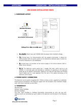
Run 4-conductor shielded cable to the thermostat from the
furnace or air handler. Connect the 4 wires to the labeled
screw terminals as shown in Figure 1A through the hole
in the thermostat backing plate. Grounding of the shielded
wiring must be done at one end only, at the furnace or air
handler end.
Exception: For systems using a non-iQ heat pump as
the outdoor unit (with an iQ modulating gas furnace), an
additional 2 wires must be run to the thermostat to connect
to the outdoor temperature sensor. Wire type may be any of
those recommended in Section A, but colors distinct from the
other 4 wires connecting to the thermostat should be used
to minimize the possibility of wiring errors. Use thermostat
backing plate terminals “GND” and “OD”. Refer to Figure
1B. Polarity is not important. See also Sections K or L.
IMPORTANT!
It essential that the wire meant to connect
to the “R” terminal (24 vac) is not mistakenly
connected to any of the other thermostat
terminals. This voltage will damage the
device!
After the wires are connected to their respective screw
terminals, plug the thermostat face into the backing plate.
Make sure that the plastic extensions on the right and left
sides of the face match up with the corresponding slots on
the backing plate before pushing the pieces together. The
thermostat face may be installed or removed with or without
control power present on the “R” terminal. Refer also to
thermostat user instructions. When the thermostat is first
powered up, check the version number which appears on the
“iQ” screen which is initially displayed. This should agree with
that noted in the System Controller column of the System
Configuration Table, for the combination of components
being installed. (Thermostat version can only be confirmed
from the powered-up display.)
C. iQ AIR CONDITIONING or iQ HEAT PUMP OUTDOOR
UNIT
Prior to beginning installation of the outdoor unit, check that
home wiring has a single phase 208/230 volt circuit dedicated
to air conditioning equipment, with circuit ampacity equal
to or exceeding that listed on the equipment nameplate.
Confirm presence of a suitable earth ground.
Refer to the Air Conditioner or Heat Pump Installation
Instructions for unit installation other than field wiring.
Line Power Wiring
Route line voltage wiring (3 wires, including earth ground)
from the indoor power panel to the outside disconnect
following National Electric Code as supplemented by local
electrical codes.
Remove the curved sheet metal housing covering the control
panel on the unit. Route line voltage wiring (3 wires, including
earth ground) from the outside disconnect through the hole
in the bottom left side of the control panel of the outdoor unit.
Connect line wires to L1 and L2 screw lugs at the base of the
contactor, and the ground wire to the grounding screw to the
left of the contactor. See Figure 2.
Control Wiring
Field-installed control wiring to the outdoor unit consists of:
• a 3-conductor shielded cable dedicated for iQ system
communication
• 2 wires for 24 vac control power. This control power
cable/wiring should be separate from the shielded cable
intended for communication.
The indoor connection of these wires is described in Sections
D through L.
4
Pass the 5 control wires into the hole in the bottom right side
of the control panel of the outdoor unit, into the small low
voltage wiring compartment. Locate the 5 corresponding
factory-wired leads with stripped ends. Assure that each
of these 5 wires (on the factory wiring side of the wire
connections) loops one time around and through the “donut”
(toroidal choke). Refer to Figure 3 which shows one wire
making a single loop.
IMPORTANT!
For iQ air conditioning units, trace the
factory-installed red wire to determine which
wire color scheme shown in Figure 4A
matches the unit. (The wires reserved for 24
volt control power are either GRY and RED
in units made starting mid-2009, or BLK and
YEL-with-black-stripes in units made prior to
mid-2009. Join each of the 5 field-run wires
to its factory-wired counterpart using a wire
nut, as shown in Figure 4A.
For iQ heat pumps join each of the 5 field-run wires to its
factory-wired counterpart using a wire nut, as shown in
Figure 4B. Figure 5 shows all these control connections
within the separate control wiring compartment of the control
panel lower right side. NOTE: the RED and GRY wires are
reserved for 24 volt control power in the heat pump. The wire
from “R” must be connected to RED, and the wire from “C”
must be connected to GRY.
IMPORTANT!
It essential that the wires meant to provide 24
volts to the outdoor unit are not mistakenly
connected to the communication terminals.
Check again before you apply power!
Outdoor EXV Board DIP Switch Settings
Check that the red DIP switch block of the EXV circuit
board (see Figure 10) located in the upper left side within
the controls compartment has been set in accordance
with Figure 8. Note that for iQ heat pumps, switch 6 is set
differently on indoor and outdoor EXV boards.
D. B5VM or B4VM iQ AIR HANDLER
Prior to beginning installation of the indoor unit, check the
proposed or existing site for the equipment for routing of
power and control wires. Follow Air Handler Installation
Instructions for hardware and line power installation of
the unit.
External Control Wiring
Field-installed control wiring consists of:
• a 4-conductor shielded cable connecting from the
air handler to the thermostat (control power plus
communications)
• a3-conductor(minimum)shieldedcableconnectingfrom
the air handler to the outdoor unit (communications)
• 2wiresfor24vaccontrolpowertotheoutdoorunit.This
control power cable/wiring should be separate from the
shielded cable intended for communication.
Refer to Figures 6, 7, and 12. Locate the 3½” x 4” interface
circuit board (with 4 black rectangular relay blocks next to a
6-screw terminal strip) in the blower compartment. On that
board locate three white connectors along one edge. The
middle one, marked “OD UNIT” on the edge of the board, has
three wires (YEL*, WHT, GRN) with stripped ends (pigtails).
First assure that each of these 3 wires loop once around
and through the “donut” (toroidal choke) as shown in Figure
3. Using wire nuts, connect these wires to the field-installed
shielded wiring which connects to the three communication
wires of the outdoor unit (Section C of this document).
* Earlier B5VM units used RED, WHT, GRN for these
communication wires.
On the same indoor interface circuit board, locate the two
leftmost screw terminals, labeled “R” and “C”, and locate the
“donut” (toroidal choke) as shown in Figure 3. Pass the two
field-installed wires which connect to the control power wires
of the outdoor unit (Section C of this document) through the
toroid two times (one loop). Connect these wires to the “R”
and “C” screw terminals. Match the wire terminations with
the outdoor unit control wires as follows:
Control Wiring to iQ A/C Unit
Communication Wiring
Interface Board
Terminal
Interface
Board plug
wire color
Outdoor unit wire color Inverter terminal
DX+
YEL
(or RED*)
YEL
(or RED*)
DX+
DX- WHT WHT DX-
GND GRN GRN GNDA
Control Power Wiring
R (screw)
[no factory
wire]
RED
(or BLK-striped YEL*)
(to High Pressure
Switch)
C (screw)
[no factory
wire]
GRY
(or BLK *)
(contactor coil)
* on earlier iQ A/C units
Control Wiring to iQ Heat Pump Unit
Communication Wiring
Indoor Interface
Board Terminal
Indoor Interface
Board plug wire
color
Outdoor unit wire
color
Outdoor Interface
Board Terminal (RHS
circuit board)
DX+ YEL YEL
3 pin 3 wire white
connector plug at
RHS circuit board
terminal “INDOOR”
DX- WHT WHT
GND GRN GRN
Control Power Wiring
R (screw) [no factory wire] RED “R” terminal screw
C (screw) [no factory wire] GRY (contactor coil, RHS)
* on earlier iQ A/C units
5
For iQ Air Conditioning units, be sure to confirm the outdoor
unit wire color scheme (per Figure 4A) before making the
outdoor connections.
On the same interface circuit board, locate the lower white
connector, marked “THERMOSTAT” on the edge of the
board. This connector has four wires (RED, YEL, WHT, GRN)
with stripped ends (pigtails). First assure that each of these
4 wires loop once around and through the “donut” (toroidal
choke) as shown in Figure 3. Using wire nuts, connect these
to the four field-installed wires leading to the iQ thermostat
(Section B of this document). Match the wire terminations
as follows:
Interface Board
Terminal
Interface Board plug
wire color
Thermostat Terminal
R RED R
DX+ YEL A+
DX- WHT B-
GND GRN C
Indoor EXV Board DIP Switch Settings
Check that the red DIP switch block of the EXV circuit board
(see Figure 10) located inside the blower compartment has
been set in accordance with Figure 8. Note that for systems
with an iQ Heat Pump switch 6 should be on (1), and for
systems with an iQ air conditioning unit switch 6 may be on
or off.
Accessories
If a humidifier is installed, the iQ system can be used to
control this accessory (acting as a humidistat). A 24 vac
control output is provided between the “H” output (second
screw terminal from the right on the interface board, Figure 6)
and any “C” terminal (screw or tab) to operate the humidifier.
The thermostat activates this output in order to maintain
the configured humidification setpoint when the system is
actively heating and (with Version 4.0 thermostat software
and later) when the fan is in the manual/on mode with no call
for heating or cooling.
E. G6 GAS FURNACE with iQ BLOWER KIT + C5 COIL
If this is a full furnace installation, first check the proposed
or existing equipment site for routing of power and control
wires.
Follow Gas Furnace and iQ Blower Kit Installation Instructions
for hardware and line power installation. Note: The G6
furnace without an iQ blower kit is not compatible with the
iQ system. Control power transformer kit 904077 is also
required.
Field Wiring, Coil to Furnace
Follow coil Installation Instructions for hardware installation,
including refrigeration lines.
Control wiring between the coil and the EXV board in
the furnace blower compartment, including operation
and troubleshooting, is covered in Installation Instruction
Addendum “iQ Drive EXV”, NORDYNE publication 7088380.
Control wiring between the coil and the furnace consists of
the following (see also Figure 9):
Number of
conductors in
cable
Wire colors
Number of
Positions in
Connector
Termination
in
Furnace
6 various 6 holes “EXV” on EXV board
3
WHT, GRN, BLK
(in gray sheath)
4 holes
“THERM/PRESS” on
EXV board
2 RED 3 holes
“THERM #1 #2” on
EXV board
2
RED, BLK (in
gray sheath)
2 tabs
“COIL THERMISTOR”
on interface board
• one6-wireharnessforEXVpower,terminatingina6-pin
white plug (routed through the hole in the coil cover down
to the EXV board in the furnace control compartment)
• one 3-wire harness for pressure transducer signal,
terminating in a 4-pin white plug (routed through the hole
in the coil cover down to the EXV board in the furnace
control compartment)
• one2-wireharness(redwires)foratemperaturesensor,
terminating in a 3-pin white plug (routed through the hole
in the coil cover down to the EXV board in the furnace
control compartment)
• one 2-wire cable with quick-connect terminals (routed
through the hole in the coil cover down to the interface
board in the furnace compartment).
Refer to Figures 6, 10, and 11. Make sure that the “ears”
of each connector plug faces the white plastic back on its
corresponding board terminal.
Indoor EXV Board DIP Switch Settings
Check that the red DIP switch block of the EXV circuit board
(see Figure 10) located in the blower compartment electrical
enclosure has been set in accordance with Figure 8. NOTE:
For systems with an iQ air conditioning unit switch 6 may be
on or off.
Control Power Transformer Replacement
Locate the control power transformer in the furnace burner
compartment. Replace the standard 40va control power
transformer with the 60va transformer (NORDYNE kit number
904077).
External Control Wiring
Field-installed control wiring consists of
• a4-conductorshieldedcableconnectingfromthefurnace
to the thermostat (control power plus communications)
• a 3-conductor (minimum) shielded cable connecting
from the furnace to the outdoor unit (communications)
• 2wiresfor24vaccontrolpowertotheoutdoorunit.This
control power cable/wiring should be separate from the
shielded cable intended for communication.
6
Refer to Figures 6, 7 and 12. Locate the 3½” x 4” interface
circuit board (with 4 black rectangular relay blocks next to a
6-screw terminal strip) in the blower compartment. On that
board locate three white connectors along one edge. The
middle one, marked “OD UNIT” on the edge of the board, has
three wires (YEL*, WHT, GRN) with stripped ends (pigtails).
First assure that each of these 3 wires loop once around
and through the “donut” (toroidal choke) as shown in Figure
3. Using wire nuts, connect these wires to the field-installed
shielded wiring which connects to the three communication
wires of the outdoor unit (Section C of this document).
* Earlier units used RED, WHT, GRN for these communication
wires.
On the same indoor interface circuit board, locate the two
leftmost screw terminals, labeled “R” and “C”, and locate the
“donut” (toroidal choke) as shown in Figure 3. Pass the two
field-installed wires which connect to the control power wires
of the outdoor unit (Section C of this document) through the
toroid two times (one loop). Connect these wires to the “R”
and “C” screw terminals. Match the terminations with the
outdoor unit control wires as follows:
Control Wiring to iQ A/C Unit
Communication Wiring
Interface Board
Terminal
Interface Board
plug wire color
Outdoor unit wire
color
Inverter terminal
DX+
YEL
(or RED*)
YEL
(or RED*)
DX+
DX- WHT WHT DX-
GND GRN GRN GNDA
Control Power Wiring
R (screw) [no factory wire]
RED
(or BLK-striped YEL*)
(to High Pressure
Switch)
C (screw) [no factory wire]
GRY
(or BLK *)
(contactor coil)
* on units produced prior to mid-2009
Be sure to confirm the outdoor unit wire color scheme (per
Figure 4A) before making the outdoor connections.
On the same interface circuit board, locate the lower white
connector, marked “THERMOSTAT” on the edge of the
board. This connector has four wires (RED, YEL, WHT, GRN)
with stripped ends (pigtails). First assure that each of these
4 wires loop once around and through the “donut” (toroidal
choke) as shown in Figure 3. Using wire nuts, connect these
to the four field-installed wires leading to the iQ thermostat
(Section B of this document). Match the wire terminations
as follows:
Indoor Interface Board
Terminal
Indoor Interface Board
plug wire color
Thermostat Terminal
R RED R
DX+ YEL A+
DX- WHT B-
GND GRN C
Accessories
If a humidifier is installed, the iQ system can be used to
control this accessory (acting as a humidistat). A 24 vac
control output is provided between the “H” output (second
screw terminal from the right on the interface board, Figure 6)
and any “C” terminal (screw or tab) to operate the humidifier.
The thermostat activates this output in order to maintain
the configured humidification setpoint when the system is
actively heating and (with Version 4.0 thermostat software
and later) when the fan is in the manual/on mode with no call
for heating or cooling.
F. SINGLE STAGE G7/MGC2S GAS FURNACE with
CONSTANT CFM BLOWER KIT or TWO STAGE
G7/PGC2T GAS FURNACE with CONSTANT CFM
BLOWER OPTION, + C6 COIL
If this is a full furnace installation, first check the proposed
or existing equipment site for routing of power and control
wires. Follow Gas Furnace and Constant CFM Blower
Kit Installation Instructions for hardware and line power
installation.
Note: The single stage G7/MGC2S furnace without a constant
cfm blower kit is not compatible with the iQ system. Do not
proceed if this is not a compatible equipment combination.
Field Wiring, Coil To EXV Board
Follow coil Installation Instructions for hardware installation,
including refrigeration lines.
Note that with this coil, the EXV circuit board must be field-
mounted to the outside of the coil’s enclosure, and the
following connections must be made in the field between
the EXV board and components inside the coil enclosure.
Refer to Figures 10 and 11. Make sure that the “ears” of
each connector plug faces the white plastic back on its
corresponding board terminal.
Number of
conductors in
cable
Wire colors
Number of
Positions in
Connector
EXV board
terminal
identification
6 various 6 EXV
3 WHT, GRN, BLK 4 THERM/PRESS
2 RED 3 THERM #1 #2
EXV operation and wiring troubleshooting is covered in
Installation Instruction Addendum “iQ Drive EXV”, NORDYNE
publication 7088380. This wiring is shown in the upper
portion of Figure 14.
Indoor EXV Board DIP Switch Settings
Check that the red DIP switch block of the EXV circuit board
(see Figure 10) has been set in accordance with Figure 8.
Note that for systems with an iQ Heat Pump switch 6 should
be on (1), and for systems with an iQ air conditioning unit
switch 6 may be on or off.
7
Field Wiring, Coil To Furnace Motor Control Board
Locate the blower motor control board in the control
enclosure within the furnace blower compartment. Control
wiring between the coil with its EXV board and this board
consists of installing the following 5 wires (refer to Figures
13 and 14):
• “R”wire(red,providedwiththecoil),betweentheEXV
board and the blower motor control board (both .25” tab
quick connect terminals). Attach the piggyback terminal
at the blower control board end.
• “C”wire(gray,providedwiththecoil),betweentheEXV
board and the blower motor control board (both .25” tab
quick connect terminals)
• “Y” wire (yellow, provided with the coil), between the
EXV board and the blower motor control board (.188” tab
terminal at the EXV board, .25” tab at the blower motor
control board OUTPUT terminal “Y/Y2”)
• one2-wirecablewith .25” tabquick connectterminals
(provided with the coil) to be routed through the hole in
the coil cover down to the adjacent blower control board
INPUT terminals “SENSOR” and “GND”. Polarity is not
important.
Origin Wire colors Terminal Type
Terminal(s) on
Blower Motor
Control Board
EXV Board R RED
.25” tab
(piggyback)
R
EXV Board C GRY .25” tab C
EXV Board Y YEL .25” tab Y/Y2 (OUTPUTS)
Coil Temperature
Sensor (2 wires)
RED, BLK (in gray
sheath)
2 @ .25” tabs
SENSOR, GND
(INPUTS)
Control Power Transformer Replacement
Locate the control power transformer in the furnace burner
compartment. Replace the standard 40va control power
transformer with the 60va transformer provided with the C6
coil.
External Control Wiring
Field-installed control wiring consists of
• a4-wireshieldedcableconnectingfromthefurnaceto
the thermostat (control power plus communications)
• a3-wire(ormore)shieldedcable connecting fromthe
furnace to the outdoor unit (communications)
• a 2 wire cable connection from the furnace to the
outdoor unit (24 vac control power). The control power
should not be run within the shielded cable intended for
communication.
Locate the blower motor control board in the furnace blower
compartment. Near the center of the lower edge are two
4-position terminal blocks, one above the other. The upper
one is a receptacle for a 4-pin connector, and the lower
one is either the same or a 4-position screw terminal block
(depending upon the version of the board). See Figure 15.
Each of the positions, left to right, in these two terminal sets
are identical. (Photographs used as figures in this document
show the version with the screw terminals.)
While this arrangement provides alternatives for wiring to the
thermostat and to the outdoor unit, the following describes
the recommended approach.
Using the 4-wire connector with pigtails (NORDYNE part
634680) provided with the thermostat, connect this to the
4 pin terminal as shown in Figure 16. Make sure that the
“ears” of the connector plug face the white plastic back on
the board terminal.
NOTE: Alternatively the screw terminals (if present) may
be used. Wire installation to these screw terminals may be
facilitated by unfastening the lower portion of the board. In
order to release the board, locate plastic standoffs which
pass through holes in the board. Assure that line power
is off first! Squeeze “wings” on these standoffs with needle
nose pliers to allow the board to be lifted from them. When
finished, the board will snap back onto the standoffs. When
connecting to screw terminals, it is essential that there be no
“strand shorts” between adjacent connections.
Using wire nuts or similar hardware, connect the 4 wires
leading to the iQ thermostat/controller and 3 wires providing
communication with the outdoor unit to these terminals as
shown in the following table. Note that the right side terminal
(R) will only join with one wire (to the thermostat). The other
3 terminals (YEL, WHT, GRN) will each join two other wires
– one to the thermostat and one to the outdoor unit. See
Figure 17.
8
Pin or screw
Position
Blower Control
Board Terminal
wire color
(connector
634680)
Destination Terminal(s)
1 (right) R RED Thermostat R
2 DX+ YEL
Thermostat A+
Outdoor unit YEL* wire
(DX+)
3 DX- WHT
Thermostat B-
Outdoor unit WHT wire (DX-)
4 (left) C GRN
Thermostat C
Outdoor unit GRN wire
(GND)
* RED in iQ A/C units made before mid-2009
IMPORTANT!
If the “R” wire is incorrectly connected to
one of the communication terminals, it will
damage the device!
Control power is provided to the outdoor unit from R and
C source terminals. There are several possible sources for
these within the furnace. The recommended sources are
the R and C screw terminals on the furnace board located
in the burner compartment. It is strongly recommended that
R and C be run in a separate cable/group from the shielded
communication wires.
The R and C screw terminals are shown for the single stage
G7 furnace board in Figure 18 and for the two stage board in
Figure 19. For iQ Air Conditioning units, be sure to confirm
the outdoor unit wire color scheme (per Figure 4A) before
making the outdoor connections. 24 volt control power must
NOT be connected to a DX+ terminal on the inverter board!
Furnace Board
Screw Terminal
iQ Outdoor Unit Wires
iQ Air Conditioner iQ Heat Pump
R
RED
(or black-striped yellow)
RED
C
GRY
(or BLK)
GRY
Accessories
If a humidifier is installed, the iQ system can be used to
control this accessory (acting as a humidistat). A 24 vac
control output is provided between the “H” output (the bottom
tab in the OUTPUTS group on the motor control board,
Figure 13) and any “C” terminal to operate the humidifier.
The thermostat activates this output in order to maintain
the configured humidification setpoint when the system is
actively heating and (with Version 4.0 thermostat software
and later) when the fan is in the manual/on mode with no call
for heating or cooling.
In order to take full advantage of the humidification capabilities
of the iQ thermostat (including humidification when the fan
is in the manual/on mode with no call for heating or cooling),
provide full time 115 vac to the humidifier (if required by
that device) from any external source rather than from the
furnace board.
An electronic air cleaner (EAC) may be powered with 115 vac
from the “EAC” tab (.25”) at the base of the furnace control
board in the burner compartment. This tab is energized
whenever the furnace is operating and calling for the blower
to run.
G. SINGLE STAGE G7/MGC2S GAS FURNACE with
CONSTANT CFM BLOWER KIT or TWO STAGE
G7/PGC2T GAS FURNACE with CONSTANT CFM
BLOWER OPTION, + C5 COIL
While the G7 furnaces are designed and intended to be
matched with C6 coils, it is understood that in some cases
they will be instead installed with C5 coils. This section
addresses that situation. Such a system is not compatible
with an iQ heat pump.
Expect that extra sheet metal adaptation will be required,
since the coil and furnace widths will not match.
Required NORDYNE parts not provided with thermostat,
coil, or furnace:
• EXVcircuitboard624734
• control power transformer NORDYNE part number
622396
For this system an EXV circuit board must be purchased and
installed separately. It is not provided with either the C5 coil
or with the furnace. Select a vertical surface where there is
no possibility of wetting or other contamination for mounting
the EXV board. On this surface drill four 3/16” holes in a 3.0”
x 3.5” rectangular pattern.
Otherwise, follow the field wiring instructions of Section F.
H. G7/PGC2 MODULATING GAS FURNACE + C6 COIL +
iQ AIR CONDITIONER or iQ HEAT PUMP
If this is a full furnace installation, first check the proposed or
existing equipment site for routing of power and control wires.
Follow iQ Modulating Gas Furnace Installation Instructions
for hardware and line power installation.
Field Wiring, Coil To EXV Board
Follow coil Installation Instructions for hardware installation,
including refrigeration lines. Note that with this coil the EXV
circuit board must be field-mounted to the coil’s enclosure,
and the following connections must be made in the field
between the EXV board and components inside the coil
enclosure. Refer to Figures 10 and 11. Make sure that the
“ears” of each connector plug faces the white plastic back on
its corresponding board terminal.
9
Number of
conductors in
cable
Wire colors
Number of
Positions in
Connector
EXV board
terminal
identification
6 various 6 EXV
3 WHT, GRN, BLK 4 THERM/PRESS
2 RED 3 THERM #1 #2
EXV operation and wiring troubleshooting is covered in
Installation Instruction Addendum “iQ Drive EXV”, NORDYNE
publication 7088380. This wiring is shown in the upper
portion of Figure 14.
Indoor EXV Board DIP Switch Settings
Check that the red DIP switch block of the EXV circuit board
(Figure 10) has been set in accordance with Figure 8. Note
that for systems with an iQ Heat Pump switch 6 should be on
(1), and for systems with an iQ air conditioning unit switch 6
may be on or off.
Field Wiring, Coil To Furnace Motor Control Board
Locate the blower motor control board in the furnace blower
compartment. Control wiring between the coil with its EXV
board and this board consists of installing the following 5
wires (see Figures 13 and 14):
• “R”wire(red,providedwiththecoil),betweentheEXV
board and the blower motor control board (both .25” tab
quick connect terminals). Note that the red wire from the
EXV board has a piggy back terminal which will allow
it and the blue wire (used for the furnace) to share the
“R” terminal at the blower board. Attach the piggyback
terminal at the blower control board end.
• “C”wire(gray,providedwiththecoil),betweentheEXV
board and the blower motor control board (both .25” tab
quick connect terminals)
• “Y” wire (yellow, provided with the coil), between the
EXV board and the blower motor control board (.188” tab
terminal at the EXV board, .25” tab at the blower control
board OUTPUT terminal “Y/Y2”)
• one2-wirecablewith .25” tabquick connectterminals
(provided with the coil) to be routed through the hole in
the coil cover down to the adjacent blower control board
INPUT terminals “SENSOR” and “GND”. Polarity is not
important.
Origin Wire colors Terminal Type
Terminal(s) on
Blower Motor
Control Board
EXV Board R RED
.25” tab
(piggyback)
R
EXV Board C GRY .25” tab C
EXV Board Y YEL .25” tab Y/Y2 (OUTPUTS)
Coil Temperature
Sensor (2 wires)
RED, BLK (in gray
sheath)
2 @ .25” tabs
SENSOR, GND
(INPUTS)
External Control Wiring
Field-installed control wiring consists of
• a4-wireshieldedcableconnectingfromthefurnaceboard
to the thermostat (control power plus communications)
• a3-wire(ormore)shieldedcable connecting fromthe
furnace to the outdoor unit (communications)
• a 2 wire cable connection from the furnace to the
outdoor unit (24 vac control power). The control power
should not be run within the shielded cable intended for
communication.
This wiring is slightly different from the single or two stage G7
furnace due to differences in the furnace board and different
terminal usage on the motor control board.
Locate the furnace control board in the burner compartment.
Find a block of four screw terminals near the top edge of the
board labeled “R DX+ DX- C”. Refer to Figures 20, 21, and
22. Connect these to the iQ thermostat as follows:
Furnace Board Terminal Thermostat Terminal
R R
DX+ A+
DX- B-
C C
When connecting to screw terminals, it is essential that there
be no “strand shorts” between adjacent connections.
Locate the blower motor control board in the furnace blower
compartment. Near the center of the lower edge are two
4-position terminal blocks, one above the other. The upper
one is a receptacle for a 4-pin connector, and the lower
one is either the same or a 4-position screw terminal block
(depending upon the version of the board). See Figure 15.
The function of each of the positions, left to right, in these two
terminal sets is identical. (Photographs used as figures in
this document show the version with the screw terminals.)
While this arrangement provides alternatives for wiring to the
thermostat and to the outdoor unit, the following describes
the recommended approach.
Using the 4-wire connector with pigtails (NORDYNE part
634680) provided with the thermostat, connect this to the
unused 4 pin terminal marked “C DX- DX+ R”. Make sure
that the “ears” of the connector plug face the white plastic
back on the board terminal.
NOTE: If the screw terminals are present, they must be used.
This approach is shown in Figure 23. Wire installation to
these screw terminals may be facilitated by unfastening the
lower portion of the board. In order to release the board,
locate plastic standoffs which pass through holes in the
board. Assure that line power is off first! Squeeze “wings” on
these standoffs with needle nose pliers to allow the board to
be lifted from them. When finished, the board will snap back
onto the standoffs. When connecting to screw terminals, it is
essential that there be no “strand shorts” between adjacent
connections.
10
Connect the 4 wires providing communication and control
power to the outdoor unit to these terminals. Note that only
the left side terminal (“C”) will connect to two wires. The
other 3 terminals will each have a single destination at the
outdoor unit. See Figure 22. Utilize the terminals on the
motor control board to connect to the outdoor unit as follows:
In the table “Destination Terminal” is for reference only –wire-
to-wire connections only are required.
Wiring Summary, Blower Control Board to Outdoor Unit
(iQ Air Conditioner)
Pin or screw
Position
Blower
Control Board
Terminal
wire color
(connector
634680)
Outdoor Unit
Matching Wire
Destination
Terminal
1 (right) R RED
RED
(or BLK-striped
YEL)*
OD unit high
pressure switch
2 DX+ YEL
YEL
(or RED)*
OD Unit Inverter
DX+
3 DX- WHT WHT
OD Unit Inverter
DX-
4 (left) C GRN
GRN
OD Unit Inverter
GNDA
GRY (or BLK)*
OD unit
contactor coil
* in iQ A/C units made before mid-2009
Wiring Summary, Blower Control Board to Outdoor Unit
(iQ Heat Pump)
Pin or screw
Position
Blower
Control Board
Terminal
wire color
(connector
634680)
Outdoor Unit
Matching Wire
Destination
Terminal
1 (right) R RED RED
OD interface
board “R” screw
terminal
2 DX+ YEL YEL
OD interface bd
“INDOOR” DX+
3 DX- WHT WHT
OD interface bd
“INDOOR” DX-
4 (left) C GRN
GRN
OD interface bd
“INDOOR” GND
GRY
OD unit
contactor coil
IMPORTANT!
If the “R” wire is incorrectly connected to
one of the communication terminals, it will
damage the device!
Accessories
For humidifier or electronic air filter control wiring refer to
“Accessories” under Section F.
I. G7/PGC2 MODULATING GAS FURNACE + NON-
IQ SINGLE STAGE AIR CONDITIONER or NO AIR
CONDITIONER
If this is a full furnace installation, first check the proposed or
existing equipment site for routing of power and control wires.
Follow iQ Modulating Gas Furnace Installation Instructions
for hardware and line power installation.
Field wiring is similar to Section H except that wiring to the
A/C condensing unit (if present) is simpler, and there are no
connections between the furnace and the coil.
External Control Wiring
Field-installed control wiring consists of
• a4-wireshieldedcableconnectingfromthefurnaceto
the thermostat (control power plus communications)
• a2wireconnectionfromthefurnacetotheoutdoorunit
(24 vac compressor start signal).
Locate the furnace control board in the burner compartment.
Find a block of four screw terminals near the top edge of the
board labeled “R DX+ DX- C”. Refer to Figures 20, 21, and
24.
Connect these to the iQ thermostat as follows:
Furnace Board Terminal Thermostat Terminal
R R
DX+ A+
DX- B-
C C
When connecting to screw terminals, it is essential that there
be no “strand shorts” between adjacent connections.
Locate the blower motor control board in the furnace
blower compartment. Run two control wires from .25” tab
connections on the left side of the motor control board to the
outdoor unit (if present) as follows (see Figure 24).
Blower Control Board Terminal Destination Terminal(s)
“C” Outdoor unit “C”
“Y/Y2” (OUTPUTS) Outdoor unit “Y”
Accessories
For humidifier or electronic air filter control wiring refer to
“Accessories” under Section F.
J. G7/PGC2 MODULATING GAS FURNACE NON-IQ
TWO STAGE AIR CONDITIONER
If this is a full furnace installation, first check the proposed or
existing equipment site for routing of power and control wires.
Follow iQ Modulating Gas Furnace Installation Instructions
for hardware and line power installation.
Field wiring is similar to Section H except that wiring to the
A/C condensing unit is simpler, and there are no connections
between the furnace and the coil.
External Control Wiring
Field-installed control wiring consists of
• a4-wireshieldedcableconnectingfromthefurnaceto
the thermostat (control power plus communications)
• a3or4-wireconnectionfromthefurnacetotheoutdoor
unit (4-wire for NORDYNE air conditioners with a Comfort
Alert module).
11
Locate the furnace control board in the burner compartment.
Find a block of four screw terminals near the top edge of the
board labeled “R DX+ DX- C”. Refer to Figures 20, 21, and
25. Connect these to the iQ thermostat as follows:
Furnace Board Terminal Thermostat Terminal
R R
DX+ A+
DX- B-
C C
When connecting to screw terminals, it is essential that there
be no “strand shorts” between adjacent connections.
Locate the blower motor control board in the furnace blower
compartment. Run three (or four) control wires from .25” tab
connections on the left side of the motor control board to the
outdoor unit as follows (see Figure 25). If the air conditioner
requires an “R” wire, use a brass Y-shaped terminal adapter
provided in the thermostat kit to allow both this field-installed
wire and the factory-installed BLU wire to be connected to
the “R” terminal on the blower motor control board.
Blower Control Board Terminal Destination Terminal(s)
“C” Outdoor unit “C”
“Y1” (OUTPUTS) Outdoor unit “Y1”
“Y/Y2” (OUTPUTS) Outdoor unit “Y2”
“R”
Outdoor unit “R”
(needed for NORDYNE A/C units with
Comfort Alert modules)
Accessories
For humidifier or electronic air filter control wiring refer to
“Accessories” under Section F.
K. G7/PGC2 MODULATING GAS FURNACE + C6 COIL +
NORDYNE NON-IQ SINGLE STAGE HEAT PUMP
If this is a full furnace installation, first check the proposed or
existing equipment site for routing of power and control wires.
Follow iQ Modulating Gas Furnace Installation Instructions
for hardware and line power installation.
Field wiring is similar to Section H except that wiring to
the outdoor unit is different, and there are no connections
between the furnace and the coil.
External Control Wiring
Field-installed control wiring consists of
• a4-wireshieldedcableconnectingfromthefurnaceto
the thermostat (control power plus communications)
• a5-wireconnectionfromthefurnacetotheoutdoorunit
(24 vac)
• a2-wireconnectionfromtheoutdoortemperaturesensor
(NORDYNE kit #920938 ) to the thermostat.
Locate the furnace control board in the burner compartment.
Find a block of four screw terminals near the top edge of the
board labeled “R DX+ DX- C”. Refer to Figures 20, 21, and
26. Connect these to the iQ thermostat as follows:
Furnace Board Terminal Thermostat Terminal
R R
DX+ A+
DX- B-
C C
When connecting to screw terminals, it is essential that there
be no “strand shorts” between adjacent connections.
Locate the blower motor control board in the furnace blower
compartment. Run five control wires from the motor control
board (4 from the left side, 1 from the right side) as follows
to the outdoor unit’s defrost control board. All are .25” tab
terminals. (See Figure 26) Use a brass Y-shaped terminal
adapter provided in the thermostat kit to allow both the field-
installed “R” wire and the factory-installed BLU wire to be
connected to the “R” terminal on the blower motor control
board.
Blower Control Board Terminal Destination Terminal(s)
“C” Outdoor unit defrost board “C”
“R” Outdoor unit defrost board “R”
“Y/Y2” (OUTPUTS) Outdoor unit defrost board “Y”
“W/O” (OUTPUTS) Outdoor unit defrost board “O”
“Y1/E” (INPUTS) Outdoor unit defrost board “W2”
Install the outdoor temperature sensor (from NORDYNE kit
#920938) in a location that would be expected to provide a
reasonably accurate temperature reading in cold weather.
Splice the ends of the sensor leads to wires which are to be
routed to the thermostat. Connect to thermostat terminals
“OD” and GND”. See Figure 1B. Refer also to the installation
instructions included with the kit for more details.
Accessories
For humidifier or electronic air filter control wiring refer to
“Accessories” under Section F.
L. G7/PGC2 MODULATING GAS FURNACE + C6 COIL +
NORDYNE NON-IQ TWO STAGE HEAT PUMP
If this is a full furnace installation, first check the proposed or
existing equipment site for routing of power and control wires.
Follow iQ Modulating Gas Furnace Installation Instructions
for hardware and line power installation.
Field wiring is similar to Section H except that wiring to
the outdoor unit is different, and there are no connections
between the furnace and the coil.
External Control Wiring
Field-installed control wiring consists of
• a4-wireshieldedcableconnectingfromthefurnaceto
the thermostat (control power plus communications)
12
• a6-wireconnectionfromthefurnacetotheoutdoorunit
(24 vac)
• a2-wireconnectionfromtheoutdoortemperaturesensor
(NORDYNE kit #920938 ) to the thermostat.
Locate the furnace control board in the burner compartment.
Find a block of four screw terminals near the top edge of the
board labeled “R DX+ DX- C”. Refer to Figures 20, 21, and
27. Connect these to the iQ thermostat as follows:
Furnace Board Terminal Thermostat Terminal
R R
DX+ A+
DX- B-
C C
When connecting to screw terminals, it is essential that there
be no “strand shorts” between adjacent connections.
Locate the blower motor control board in the furnace blower
compartment. Run six control wires from the motor control
board (5 from the left side, 1 from the right side) as follows
to the outdoor unit’s defrost control board. All are .25” tab
terminals. (See Figure 27) Use a brass Y-shaped terminal
adapter provided in the thermostat kit to allow both the field-
installed “R” wire and the factory-installed BLU wire to be
connected to the “R” terminal on the blower motor control.
Blower Control Board Terminal Destination Terminal(s)
“C” Outdoor unit defrost board “C”
“R” Outdoor unit defrost board “R”
“Y1” (OUTPUTS) Outdoor unit defrost board “Y”
“Y/Y2” (OUTPUTS) Outdoor unit defrost board “Y2”
“W/O” (OUTPUTS) Outdoor unit defrost board “O”
“Y1/E” (INPUTS) Outdoor unit defrost board “W2”
Install the outdoor temperature sensor (from NORDYNE kit
#920938) in a location that would be expected to provide a
reasonably accurate temperature reading in cold weather.
Splice the ends of the sensor leads to wires which are to be
routed to the thermostat. Connect to thermostat terminals
“OD” and GND”. See Figure 1B. Refer also to the installation
instructions included with the kit for more details.
Accessories
For humidifier or electronic air filter control wiring refer to
“Accessories” under Section F.
M. iQ ZONE WIRING
This section describes how to connect an iQ Zone system to
an iQ heating and/or cooling system described under any of
the preceding sections. A single plug-in 12 volt dc power supply
provided with iQ zone serves all zoning network components
(main Airzone control board, local zone thermostats, zone
modules, and damper motors).
iQ Zone System Wiring
Installation of the iQ Zone system requires wiring between all
zoning system components (main Airzone control board, local
zone thermostats, zone modules, and damper motors). It is
assumed that all of this has been completed following the iQ
Zone Installation Instructions (separate document). Figure 28
shows the wiring between these components for reference.
Recommended cable for wiring between modules is shielded
4-conductor cable, AWG20, stranded copper.
Zone wiring shielding should only be connected to ground at
one point, e.g. at the ground symbol terminal on the Airzone
control board. The shielding wires for each segment of zone
control wiring should be interconnected by twisting, external
to the connector blocks.
External Control Wiring
The only additional field wiring required is the interconnection
between the rest of the iQ communication bus to the Airzone
control board (Figures 28 and 29) and grounded shielding.
Connect these wires as follows, splicing into the iQ bus at
any convenient location (usually in the furnace or air handler).
iQ Bus Conductor Airzone Control Board Terminal
A+ or DX+ A
GND or C None
B- or DX- B
Shielding
NOTE: The third iQ communication bus wire (GND or C)
should not be connected to the zone control board, since
for some equipment the ‘C’ connection is floating and not
grounded. Zone system wire shielding should be connected
as indicated in Figure 28, at the earth ground symbol, and it
should not be grounded elsewhere in the zone system circuit.
Grounding for all zone system wiring is made through the iQ
wire shielding to its sole ground point (e.g. in a furnace).
13
Table A2. Equipment Configurations Addressed (with model and SKU numbers)
See Sections Indoor Unit Indoor Coil Outdoor Unit System Controller
A, B, C, D
B4VM, B5VM, B6VM iQ Air Handler
Models:
B5VM-E36K-B (SKU 904390E)
B5VM-E48K-C (SKU 904391E)
PAH2VM E36KB (SKU 904390PE)
PAH2VM E48KC (SKU 904391PE)
B4VM-E24K-B (SKU 920778)
B4VM-E36K-B (SKU 920779)
B4VM-E48K-C (SKU 920780)
PAH4VM E24KB (SKU 920778P)
PAH4VM E36KB (SKU 920779P)
PAH4VM E48KC (SKU 920780P)
B6VMAI 24K-B (SKU 921173)
B6VMAI 36K-B (SKU 921174)
B6VMAI 48K-C (SKU 921175)
(included with Air Handler)
iQ A/C Condensing Unit
Models:
FS4BI-024KA (SKU 919281F)
FS4BI-036KA (SKU 919282F)
FS4BI-048KA (SKU 919283F)
PSA4BI-024KA (SKU 919281P
PSA4BI-036KA (SKU 919282P)
PSA4BI-048KA (SKU 919283P)
iQ Thermostat
Models (all):
919724 919724A
919725, 919725A
920622, 920623
920339A,C,D,E,F, G
920340A,C,D,E,F, G
(Software versions 1.4
and later)
A, B, C, E
G6 Furnace with iQ Blower Kit
iQ Blower Kit: SKU 904621 or
FG6TE nnnC-IQx or
FG6TE nnnN-IQx
(where n is a number and x may be a
letter or absent)
(SKU range 904623F to 904630F,
904582F to 904589F)
(NOTE: G6 furnaces are not
compatible with iQ Zone.)
C5 Coil
Coil Models:
C5BH-E36C-B (SKU
919230E)
C5BH-E48C-C (SKU
919231E)
E36 FRU SKU 919457E
E48 FRU SKU 919458E
iQ A/C Condensing Unit
Models:
as above
iQ Thermostat
Models (all):
919724 919724A
919725, 919725A
920622, 920623
920339A,C,D,E,F,G
920340A,C,D,E,F,G
(Software versions 1.4
and later)
A, B, C, F
1 Stage G7 Gas Furnace
with Constant CFM Blower Kit
Furnace Models:
numbers containing “G7S” or
“MGC2S”
Blower Kit Models:
SKUs 904876, 904877, 904878,
904879
C6 Coil
Models:
C6BH-Ennx-x (where n is a
number and x is any letter),
SKUs 920162 to 920165 and
920409 to 920412
iQ A/C Condensing Unit
Models:
as above
iQ Thermostat
Models:
920622, 920623
920339C,D,E,F,G
920340C,D,E,F,G
(Software versions 3.1
and later)
A, B, C, F
2 Stage G7 Gas Furnace
with Constant CFM Option
Furnace Models:
FG7Tx nnnx-Vx or PGC2Tx nnnx-Vx
(where n is a number and x is any
letter) SKUs: 904709F to 904726F,
904735F to 904742F, 904709P to
904726P, 904735P to 904742P
C6 Coil
Models:
C6BH-Ennx-x (where n is a
number and x is any letter),
SKUs 920162 to 920165 and
920409 to 920412
iQ A/C Condensing Unit
Models:
as above
iQ Thermostat
Models:
920622, 920623
920339C,D,E,F,G
920340C,D,E,F,G
(Software versions 3.1
and later)
A, B, C, G
1 Stage G7 Gas Furnace
with Constant CFM Blower Kit
Furnace Models:
numbers containing “G7S” or
“MGC2S”
Blower Kit Models:
SKUs: 904876, 904877, 904878,
904879
C5 Coil
Models:
C5BH-E36C-B (SKU
919230E)
C5BH-E48C-C (SKU
919231E)
E36 FRU SKU 919457E
E48 FRU SKU 919458E
iQ A/C Condensing Unit
Models:
as above
iQ Thermostat
Models:
920622, 920623
920339C,D,E,F,G
920340C,D,E,F,G
(Software versions 3.1
and later)
A, B, C, G
2 Stage G7 Gas Furnace
with Constant CFM Option
Furnace Models:
FG7Tx nnnx-Vx or PGC2Tx nnnx-Vx
(where n is a number and x is any
letter) SKUs: 904709F to 904726F,
904735F to 904742F, 904709P to
904726P, 904735P to 904742P
C5 Coil
Models:
C5BH-E36C-B (SKU
919230E)
C5BH-E48C-C (SKU
919231E)
E36 FRU SKU 919457E
E48 FRU SKU 919458E
iQ A/C Condensing Unit
Models:
as above
iQ Thermostat
Models:
920622, 920623
920339C,D,E,F,G
920340C,D,E,F,G
(Software versions 3.1
and later)
A, B, C, H
G7 Modulating Gas Furnace
Furnace Models:
numbers containing “FG7MQ” or
“PGC2MQ” SKUs: 904743F to
904746F, 904743P to 904746P
C6 Coil
Models:
C6BH-Ennx-x (where n is a
number and x is any letter),
SKUs 920162 to 920165 and
920409 to 920412
iQ A/C Condensing Unit
Models:
as above
iQ Thermostat
Models:
920339C,D,E,F,G
920340C,D,E,F,G
(Software versions
4.0 and later)
14
See Sections Indoor Unit Indoor Coil Outdoor Unit System Controller
A, B, C, D
B4VM or B6VM iQ Air Handler
Models:
B4VM-E24K-B (SKU 920778)
B4VM-E36K-B (SKU 920779)
B4VM-E48K-C (SKU 920780)
PAH4VM E24KB (SKU 920778P)
PAH4VM E36KB (SKU 920779P)
PAH4VM E48KC (SKU 920780P)
B6VMAI 24K-B (SKU 921173)
B6VMAI 36K-B (SKU 921174)
B6VMAI 48K-C (SKU 921175)
(included with Air Handler)
iQ Heat Pump
Models:
FT4BI-024K (SKU 920269F)
FT4BI-036K (SKU 920270F)
FT4BI-048K (SKU 920271F)
PSH4BI-024K (SKU 920269P)
PSH4BI-036K (SKU 920270P)
PSH4BI-048K (SKU 920271P)
iQ Thermostat
Models:
920339D,E,F,G
920340D,E,F,G
(Software versions 5.0
and later)
A, B, C, F
1 Stage G7 Gas Furnace
with Constant CFM Blower Kit
Furnace Models:
numbers containing “G7S” or
“MGC2S”
Blower Kit Models:
SKUs 904876, 904877, 904878,
904879
C6 Coil
Models:
C6BH-innx-x, SKUs 920781 to
920785 and 920790 to 920794
iQ Heat Pump
Models:
as above
iQ Thermostat
Models:
920339D,E,F,G
920340D,E,F,G
(Software versions 5.0
and later)
A, B, C, F
2 Stage G7 Gas Furnace
with Constant CFM Option
Furnace Models:
FG7Tx nnnx-Vx or PGC2Tx nnnx-Vx
(where n is a number and x is any
letter) SKUs: 904709F to 904726F,
904735F to 904742F, 904709P to
904726P, 904735P to 904742P
C6 Coil
Models:
C6BH-innx-x, SKUs 920781 to
920785 and 920790 to 920794
iQ Heat Pump
Models:
as above
iQ Thermostat
Models:
920339D,E,F,G
920340D,E,F,G
(Software versions 5.0
and later)
A, B, C, H
G7 Modulating Gas Furnace
Furnace Models:
numbers containing “FG7MQ” or
“PGC2MQ”
SKUs 904743F to 904746F, 904743P
to 904746P
C6 Coil
Models:
C6BH-innx-x, SKUs 920781 to
920785 and 920790 to 920794
iQ Heat Pump
Models:
as above
iQ Thermostat
Models:
920339D,E,F,G
920340D,E,F,G
(Software versions 5.0
and later)
A, B, C, I
G7 Modulating Gas Furnace
Furnace Models:
as above
Any None
iQ Thermostat
Models:
920339C,D,E,F,G
920340C,D,E,F,G
(Software versions 4.0
and later)
A, B, C, I
G7 Modulating Gas Furnace
Furnace Models:
as above
Any
Non-iQ Conventional Single
Stage A/C
Models: any
iQ Thermostat
Models:
920339C,D,E,F,G
920340C,D,E,F,G
(Software versions 4.0
and later)
A, B, C, J
G7 Modulating Gas Furnace
Furnace Models:
as above
Any
Non-iQ Conventional Two
Stage A/C
Models: any
iQ Thermostat
Models:
920339C,D,E,F,G
920340C,D,E,F,G
(Software versions 4.0
and later)
A, B, C, K
G7 Modulating Gas Furnace
Furnace Models:
as above
C6 Coil
Models:
as above
Non-iQ Conventional
NORDYNE Single Stage Heat
Pump
Models: any
iQ Thermostat
Models:
920339D,E,F,G
920340D,E,F,G
(Software versions 5.0
and later)
A, B, C, L
G7 Modulating Gas Furnace
Furnace Models:
as above
C6 Coil
Models:
as above
Non-iQ Conventional
NORDYNE Two Stage Heat
Pump
Models: any
iQ Thermostat
Models:
920339D,E,F,G
920340D,E,F,G
(Software versions 5.0
and later)
M
iQ Zone
®
with any of the above combinations (except G6 furnaces)
iQ Thermostat
Models:
920339F,G
920340F,G (Software
versions 6.0 and later)
15
FIGURES
and
DIAGRAMS
16
C
R
A+
B-
GND
GND
OD
ID
GND
R
DX+
DX-
Figure 1A. iQ Controller/Thermostat Black Plate Wiring
Figure 1A. iQ Controller/Thermostat Back Plate Wiring
Figure 1B. Thermostat Wiring Including Outdoor Temperature Sensor
(non-iQ Heat Pumps Only)
C
R
A+
B-
GND
GND
OD
ID
GND
R
DX+
DX-
OUTDOOR
TEMPERATURE
Figure 1B. Thermostat Wiring Including Outdoor Temperature Sensor
(non-iQ Heat Pumps only)
17
Figure 2. Line Voltage Connections, iQ Outdoor Unit
Figure 3. Noise Reduction Toroid
SINGLE LOOP SHOWN
Figure 3. Noise Reduction Toroid
18
Figure 4A. Control Wiring Connections, iQ Air Conditioning Outdoor Unit
CONTROL PANEL
iQ OUTDOOR UNIT
iQ COMMUNICATIONS
TO INVERTER
TO CONTACTOR
COIL THROUGH
HIGH PRESSURE SWITCH
GRN
GREY
RED
24 VAC
WHT
YEL
GND
DX-
DX+
CONTROL PANEL
iQ OUTDOOR UNIT
iQ COMMUNICATIONS
TO INVERTER
TO CONTACTOR
COIL THROUGH
HIGH PRESSURE SWITCH
GRN
BLK
YEL/BLK
24 VAC
WHT
RED
GND
DX-
DX+
Wire Color Scheme 2
Wire Color Scheme 1
Figure 4A. Control Wiring Connections, iQ Air Conditioning Outdoor Unit
19
Figure 4B.Control Wiring Connections, iQ Heat Pump Outdoor Unit
GRN
GND
DX-
DX+
WHT
YEL
RED
GRY
C R
Figure 4B. Control Wiring Connections, iQ Heat Pump Outdoor Unit
20
Figure 5. Control Wiring Connections, iQ Outdoor Unit (Air Conditioner Shown)
Figure 6. Indoor iQ Interface Board Unwired
Control Wiring
connection
Compartment
  • Page 1 1
  • Page 2 2
  • Page 3 3
  • Page 4 4
  • Page 5 5
  • Page 6 6
  • Page 7 7
  • Page 8 8
  • Page 9 9
  • Page 10 10
  • Page 11 11
  • Page 12 12
  • Page 13 13
  • Page 14 14
  • Page 15 15
  • Page 16 16
  • Page 17 17
  • Page 18 18
  • Page 19 19
  • Page 20 20
  • Page 21 21
  • Page 22 22
  • Page 23 23
  • Page 24 24
  • Page 25 25
  • Page 26 26
  • Page 27 27
  • Page 28 28
  • Page 29 29
  • Page 30 30
  • Page 31 31
  • Page 32 32
  • Page 33 33
  • Page 34 34
  • Page 35 35
  • Page 36 36
  • Page 37 37
  • Page 38 38
  • Page 39 39
  • Page 40 40

Broan B4VM-E Product information

Category
Split-system air conditioners
Type
Product information

Ask a question and I''ll find the answer in the document

Finding information in a document is now easier with AI