Page is loading ...

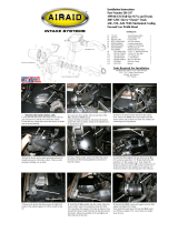
Installation Instructions
Part Number 450-238
2010 Ford Mustang GT
4.6L V-8
1. Disconnect the negative battery cable.
A.) Push the green plastic tabs on each end, and remove
the breather hose from vehicle. (Save for later use). B.)
Loosen the hose clamp that secures the intake tube to the
throttlebody. C.) Squeeze the clamp and disconnect the
resonator from the air intake tube. D.) Slide the red tab,
and disconnect the wiring harness from the Mass Air
Flow sensor (MAF).
2.A.) Using a 10mm socket, remove and save the bolt
that secures the airbox to the fender.
B.) Using a flat blade screwdriver, carefully
, push, or
pry the 5 wiring loom anchors from the factory airbox.
3. Grab the airbox and tube and roll it forward while lift-
ing up to dislodge it from the intake scoop. Remove the
assembly from the vehicle. A.) Remove the two factory
grommets and then replace them back into the two holes
in the inner fender. B.) Remove the steel sleeve and
grommet and save for reinstallation later. C.) Using the
provided #20 Torx bit, remove the two screws and the
MAF sensor from the tube.
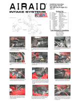
4. A.) Install the filter adapter (#9) using three 1/4-20
button head bolts (#12), and flat washers (#13) into the
Airaid Cool Air Dam (CAD) (#4) as shown. B.) Reinstall
the small grommet and sleeve (removed in step #3) into
the hole in the CAD.
5. Turn the CAD so that the bottom faces the left fender
as shown. Now reinstall the wiring loom anchors into
their respective holes starting at the back of the CAD
with the two hole anchor and work your way underneath
and towards the front. The last anchor nearest the MAF
sensor is not anchored.
6. Install the CAD into the vehicle making sure that the
scoop provision in the CAD aligns with the factory
scoop, and the two locating pins on the bottom align with
the factory grommets. Next reinstall the factory bolt that
was removed in step #2 thru the steel sleeve and grommet
and into the inner fender. Make sure that the wiring har-
ness is not pinched under the CAD.
8. Slide the Modular Venturi Tube (#3) into the Airaid
intake tube (#2) making sure to align the two slots for
the MAF sensor. Next install the MAF sensor into the
intake tube using two provided 8-32x3/8” screws (#14).
Do Not Use The Factory Screws!
Packing List:
#1 700-461 Airaid Premium Filter 1
#2 KIT238T Airaid Intake Tube 1
#3 KIT238I Modular Venturi Tube (MVT) 1
#4 KIT238CAD Cool Air Dam 1
#5 KITHUMPHS05 Urethane Hump Hose 1
#6 KITCOUPLER07 Urethane Oval Coupler 1
#7 KITCOUPLER19 Urethane 1 3/4” Coupler 1
#8 KITCAP01 Urethane Cap* 1
#9 KIT1121MAFADA Filter Adapter 1
#10 KITHOSE06 3/8”x12” Hose 1
#11 KITWSTRIP03 Weather Strip 25” 1
KIT238HP Hardware & Instructions 1
#12
KIT15DHC3050 ¼-20 Button Head Bolt 3
#13 KIT09FWZ019 ¼” Flat Washer 4
#14 KIT15BHC3038 8-32 x 3/8” Button Head Bolt 2
#15 KIT25C87HCSS 1/4-20 Hex Head Bolt 1
#16 KIT60C120HCS 6mm x 12mm Hex Bolt 1
#17 KITHS72 #72 Hose Clamp 4
#18 KITCLAMP60SS 40-60mm Hose Clamp 2
#19 KITGRMT03 Grommet 1
#20 KITPLUG01 Firewall Plug* 1
#21 KITFITTING05_REV_B Aluminum Fitting 1
#22 KIT238B Resonator Tube Bracket 1
#23 KITBIT01 #20 Torx Bit 1
Tools Required For Installation:
5/32” Allen Wrench & 3/32” Allen Wrench
1/4”, 5/16”, 10mm Deep,13mm Sockets
Ratchet & Extension, Pliers, Screwdriver, Razor Blade
7. Install the provided hump hose (#5) onto the filter
adapter using two #72 hose clamps (#17) as shown.
Leave the two hose clamps loose for now.
9. Lift up on the intake resonator tube to disengage it
from the stud securing the power steering reservoir. Us-
ing a deep 10mm socket, remove the stud and save it for a
possible optional install. See step #18.
A.
B.
C.
A.
B.
D.
A.
B.
C.
A.
B.

17. Double check your work!
Make sure there is no foreign material in the intake path. Make sure all clamps, hoses, bolts, and
screws are tight. Double check the hood clearance!
Reconnect the negative battery cable!
Airaid Filter Co. 2688 E Rose Garden Ln. Phoenix AZ 85050 (800) 498-6951 [email protected]om www.airaid.com
Before!
After!
Instructions Revision
Date: 11/01/10
Don’t Forget Your AIRAID Filter Tune-Up Kit!
P/N 790-551 Aerosol Spray
P/N 790-550 Squeeze Spray
Thank you for purchasing the Airaid Intake System. Contact Airaid @ (800) 498-6951 8:00 AM - 5:00 PM MST weekdays for questions
regarding fit or instructions that are not clear to you. Your Airaid Intake System was carefully inspected and packaged. Check that no parts are
missing, or were damaged during shipping. If any parts are missing, contact Airaid. The air filter element is protected from direct exposure to wa-
ter and debris; care should be taken not to drive through deep water. WATER INGESTION IS THE DRIVERS RESPONSIBILTY! The air filter is
reusable and should be cleaned using the Airaid Filter Tune-Up Kit periodically.
13. Install the air intake tube into the hump hose first,
and then onto the throttlebody. Adjust for fit and then
tighten all four hose clamps. Next, reinstall the factory
resonator tube into the 1 3/4” coupler and tighten the hose
clamp. Now “reseat” the resonator tube onto the bracket.
14. Install the Airaid Premium Filter (#1) onto the filter
adapter and tighten the hose clamp. Next, install the
weatherstrip (#11) onto the top of the CAD as shown
starting near the radiator and working your way towards
the left fender.
15. VERY CAREFULLY! Without cutting thru the
connectors, cut the factory breather tube on each end just
enough to remove the factory connectors.
16. Install the two factory connectors from step #15 into
each end of the supplied 3/8”x12” breather hose (#10).
Now reattach one connector to the valve cover, and the
other end to the aluminum fitting on the intake tube.
10.A.) Thread the 1/4-20 hex bolt (#15) into the resonator
bracket (#22) and tighten as shown.
B.) Slide the 6mmx12mm (#16) hex bolt thru one flat
washer (#13) and into the hole in the resonator bracket.
11. Install the bracket assembly from step #10 as shown.
This bracket and 6mm bolt will secure the power steering
reservoir and replaces the stud removed in step #9.
12.A.) Install the oval coupler onto the intake tube using
two #72 hose clamps (#17). Leave the clamps loose for
now. B.) Install the 1 3/4” coupler (#7) onto the intake
tube using two #28 hose clamps (#18) as shown. Tighten
only the clamp against the tube for now. C.) Install the
provided grommet (#19) into the intake tube and then
install the aluminum fitting (#21) into the grommet as
shown.
A. B.
A.
B.
C.
18
. Optional Installation Notice!
Airaid has made provisions to eliminate the factory air intake resonator if you so desire. The removal of the resonator
has no effect negative effect on the performance of this kit. Please see the addendum instruction sheet included with
these instructions for further information.
/