z
z

Safety precautions
When designing and manufacturing a device using CKD products, the manufacturer is obligated
to manufacture a safe product by confirming safety of the system comprising the following items:
Device mechanism
Pneumatic or water control circuit
Electric control that controls the above
It is important to select, use, handle, and maintain the product appropriately to ensure that the
CKD product is used safely.
Observe warnings and precautions to ensure device safety.
Check that device safety is ensured, and manufacture a safe device.
This product is designed and manufactured as a general industrial machine part. It
must be handled by someone having sufficient knowledge and experience.
Use this product within its specifications.
This product cannot be used beyond its specifications. Additionally, the product must not be
modified or machined.
This product is intended for use in general industrial devices and parts. Use beyond such
conditions is not considered. Consult with CKD for details when using the product beyond the
unique specification range, outdoors, or in the following conditions or environments. In any
case, measures for safety shall be provided when the vavle malfunctions.
Use for special applications requiring safety including nuclear energy, railroad, aviation,
ship, vehicle, medical equipment, equipment or applications coming into contact with
beverage or food, amusement equipment, emergency shutoff circuits, press machine, brake
circuits, or for safeguard.
Use for applications where life or assets could be adversely affected, and special safety
measures are required.
Observe corporate standards and regulations, etc., related to the safety of device
design and control, etc.
ISO4414, JIS B 8370 (pneumatic system rules)
JFPS2008 (principles for pneumatic cylinder selection and use)
Including High Pressure Gas Maintenance Law, Occupational Safety and Sanitation Laws,
other safety rules, standards and regulations, etc.
Do not handle, pipe, or remove devices before confirming safety.
Inspect and service the machine and devices after confirming safety of the entire system
related to this product.
Note that there may be hot or charged sections even after operation is stopped.
When inspecting or servicing the device, turn off the energy source (air supply or water
supply), and turn off power to the facility. Release any compressed air from the system, and
pay enough attention to possible water leakage and leakage of electricity.
When starting or restarting a machine or device that incorporates pneumatic components,
make sure that system safety, such as pop-out prevention measures, is secured.
Observe warnings and cautions on the pages below to prevent accidents.

■The safety cautions are ranked as "DANGER", "WARNING" and "CAUTION" in this
section.
When a dangerous situation may occur if handling is mistaken
leading to fatal or serious injuries, or when there is a high degree
of emergency to a warning.
When a dangerous situation may occur if handling is mistaken
leading to fatal or serious injuries.
When a dangerous situation may occur if handling is mistaken
leading to minor injuries or physical damage.
Note that some items described as "CAUTION" may lead to serious results depending
on the situation. In any case, important information that must be observed is explained.
Precautions with regard to guarantee
z Guarantee period
The guarantee period of our product shall be one (1) year after it is delivered to the place
specified by the customer.
z Guarantee coverage
If any failure for which CKD CORPORATION is recognized to be responsible occurs within the
above warranty period, a substitute or necessary replacement parts shall be provided free of
charge, or the product shall be repaired free of charge at the plant of CKD CORPORATION.
However, the guarantee excludes following cases:
Defects resulting from operation under conditions beyond those stated in the
catalogue or specifications.
Failure resulting from malfunction of the equipment and/or machine manufactured
by other companies.
Failure resulting from wrong use of the product.
Failure resulting from modification or repairing that CKD CORPORATION is not
involved in.
Failure resulting from causes that could not be foreseen by the technology available
at the time of delivery.
Failure resulting from disaster that CKD is not responsible of.
Guarantee stated here covers only the delivered products. Any other damage resulting from failure
of the delivered products is not covered by this guarantee.
z Confirmation of product compatibility
Our customer shall be responsible of confirming compatibility of our product used in our
customer’s system, machinery or device.

Contents
Glossary
Unpacking
Installation
Conditions for installation
Installation method
Piping
Wiring
Pre-operation (post-installation) check
Appearance check
Leakage check
Electrical check
Operation check
Instructions for proper use
Handling precautions
Manual override (For options with manual override)
Maintenance
Maintenance and inspection
Repairing of the explosionproof solenoid valves
Troubleshooting
Appropriate disposal
Internal construction
Internal construction of the normally closed 2-port valve
Internal construction of the normally open 2-port valve
Reference material
Classification of explosive gases
Classification of hazardous areas

Glossary
(1) Acts, related regulations, and related standards
In Japan, basis related to explosionproofed electrical equipments are as follows:
*Japanese Industrial Standards (JIS)
*Industrial Safety and Health Law and its related regulations
*Electricity Business Act and its related regulations.
Acts, laws, and regulations stated above are required to comply with the “Recommended
Practices for Explosion-Protected Electrical Installations in General Industries”.
(2) Recommended Practices for Explosion-Protected Electrical Installations in General
Industries
Publisher: National Institute of Occupational Safety and Health, Japan
Document name: Recommended Practices for Explosion-Protected Electrical
Installations in General Industries (Explosion-protecting of gas and steam, 2006).
Recently, “Recommended Practices for Explosion-Protected Electrical Installations in
General Industries” (Technical guide consistent with international standards 2008), which
is consistent with international standard (IEC 60079), is published.
The explosionproof solenoid valve explained in this instruction manual does not conform
with the IEC standard. It conforms with “Recommended Practices for
Explosion-Protected Electrical Installations in General Industries”
(Explosion-Protecting of gas and steam, 2006).
(3) Hazardous area
A location in which fire or explosion hazards may exist that calls for special safety
provisions to the structure, installation and specification of electrical equipments.
Hazardous locations are classified into Zone0, Zone1, and Zone2. This explosionproof
solenoid valve is classified in Zone2, since it has an “explosionproof structure of the
solenoid in solenoid valves”.
Zone2 is a location where (at normal conditions) there is little possibility of the atmosphere
becoming explosive, and the duration of the explosive atmosphere is short, even if the
explosive atmosphere is formed.
Previously, hazardous locations were classified into Location0, Location1, and Location2.
The classification was reviewed, and now they are called Zone0, Zone1, and Zone2.
(4) Explosion class and ignition temperature
Degree of hazard for explosive gases is classified by its ignition temperature and explosion
class. Explosionproofed electrical equipments are obligated to display its type of
explosionproof construction, explosion class, and ignition temperature in this order. This
display shows the type of gas, classified by explosion class and ignition temperature, the
electrical equipment is intended to handle and manage.
Our explosionproof solenoid valve displays either d2G2 or d2G4. Symbols indicate the
following :
*d: Explosionproof construction
*2: Explosion class
*G2 and G4: Ignition temperature
The classification above restricts manageable explosive gases.
Within our explosionproof solenoid valves, the following models are classified into d2G4:
AP11E4, AP12E4, AP21E4, and AP22E4
The following model is classified into d2G2:
AP11E2, AP12E2, AP21E2, and AP22E2

Unpacking
Do not remove the port covering until just before piping.
Otherwise, foreign matter enters the valve and cause
malfunction or bad operation.
(1) Check that the model No. shown on the Name Plate of the product is the same with
what you ordered.
(2) Check that the product has no external damages.
(3) When storing the product, keep the product inside the packing box to prevent the
intrusion of foreign matter to the valve. Take out the valve when piping.
Installation
This explosionproof solenoid valve is certified as having an
explosionproof construction in the “Recommended Practices
for Explosion-Protected Electrical Installations in General
Industries”.
If this product is used as an explosionproof electrical
equipment, the product cannot be used beyond specifications,
since its use is regulated by law.
Conditions for installation
a) Confirm the explosion class and ignition temperature of the
explosive gas. Make sure the explosionproof class of the
solenoid valve conforms with the explosion class and
ignition temperature of the gas.
Some gases such as hydrogen and acetylene cannot be
conveyed even with explosionproof construction valves.
b) Confirm that the fluid pressure, fluid temperature, and
ambient temperature are within specifications.
Observe specifications, since fluid pressure affects
operation of the solenoid valve, and since temperature
affects the risk of explosion.
c) The coil generates heat.
Do not use this product in a sealed container. Provide
ventilation measures.
d) The product cannot be used in a corrosive or solvent
environment.
e) Avoid humid environments, since condensation may occur
with change in temperature.
f) This explosionproof construction is intended for factory use.
Do not use this valve for coal mines or marine vessels.
(1) Provide appropriate measures to prevent the product from freezing at cold places.
(2) This product can be used outdoors.
Ingress Protection code rating defined in JIS C0920 is IP65.
(3) Do not wash the product with water or solvents. Do not paint the product. Resin
material used in the product may break down.
(4) Do not use the product under vibration or inertia.
For normally open valves (model: AP12E4, AP12E2, AP22E4, and AP22E2), the
plunger within will vibrate and may result in beat sounds or malfunction.

Installation method
a) Read this instruction manual thoroughly and understand
the contents before installing the product.
b) Always take hold of the body portion when handling and
mounting the product.
c) Confirm leakage from the piping after installation.
(1) Mounting posture is unrestricted under operation pressure differential range.
Since this product uses fluid pressure to operate, pressure beyond specified range
destabilizes operation.
Moreover, avoid positioning the coil side down, since foreign matter in the fluid
accumulates around the plunger and result in beat sounds and malfunction.
(2) Provide enough space for safe maintenance and troubleshooting work.
Piping
a) When piping or re-piping, fix the product.
b) Fix and provide appropriate support to the piping, so that
the weight and vibration of the piping will not directly be
applied to the product.
c) When piping is finished and fluid is to be flown, supply
pressure gradually.
If the piping is improper, the piping may disconnect or
the fluid may leak.
(1) Installing a bypass circuit
To ease maintenance work, install a bypass circuit in the piping (Refer to Figure 1.).
(Figure 1.) Bypass circuit
Gate valve Strainer
Solenoid valve (this
p
roduct) Union
j
oint

(2) When installing the product on a drain circuit of a tank
When installing the product to control drain from a tank, do not
install the product at the bottom of the tank. Otherwise, foreign
matter accumulated at the bottom of the tank enters the
product and cause malfunction. Install the product a little
above the tank bottom (Refer to Figure 2.).
(3) Connecting the product directly with a regulator
If a regulator and a solenoid valve are directly connected, they
may enter into resonance with each other and cause
malfunction. (Refer to Figure 3.)
(4) Sectional area of the piping
Select piping bore so that the sectional area of the piping at the fluid supply side does not
restrict flow. Select piping that matches with the port size of the solenoid valve.
Even if fluid pressure at the fluid supply side is within specifications when the valve is
closed, fluid pressure at that side drops drastically when the valve opens if the sectional
area of the piping at that side is restricted. As a result, restricting the sectional area of the
piping at the fluid supply side will reduce pressure differential, destabilizing the solenoid
valve operation. Refer to “4.1 Handling precautions” for details.
(5) Cleaning the piping
Before piping, flush the piping with compressed air 0.3MPa or more to remove foreign
material such as dust, metal powder, rust, and sealing material.
(6) Removal of foreign matter
Foreign matter such as dust in the fluid causes malfunction and leakage.
To remove foreign matter, attach an appropriate apparatus to the primary side of the
product. When the fluid is air, attach a filter 5µm or finer. When the fluid is water, attach a
strainer 80 mesh or finer.
(7) When the fluid is steam
When the fluid is steam, a drain trap must be installed. Steam generated in a boiler contains
a large amount of drain that needs to be removed.
Incline the steam circuit piping: slope of 1 in 250 going down, and 1 in 80 going up. Install the
drain trap where drain is likely to pool.
When the fluid is steam, a device to soften supply water, and a filter for steam must be
installed. Supply water to the boiler contains calcium salts and magnesium salts, which react
with oxygen and carbon dioxide. The reaction makes scale and sludge that needs to be
removed.
(8) Piping
Make sure that the piping port is correct.
Match the fluid flow direction with the arrow shown on the product body.
(Figure 2.) Drain circuit from
the tank
(Figure 3.) Connecting the
product directly to a regulator

(9) Sealing material
When using sealing material, make sure the sealing material do not enter the piping. Also,
make sure there is no external leakage. When taping seal tape to the pipe thread, leave 1 to
2 threads at the tip without taping.
Also, when using liquid sealing material, leave 1 to 2 threads at the tip without sealing
material. Do not apply too much sealing material on the thread. Do not apply sealing
material to the internal thread (refer to Figure 4.).
(10) Tightening
Refer to Table 1. for the recommended port tightening torque.
Table 1. Recommended port tightening torque
(11) Lubricated or non-lubricated operation
This product does not require lubrication. Therefore, no lubricator is needed.
If the product is to be lubricated, use turbine oil Class 1, ISO VG32 (additive-free) or
equivalent. Once lubricated, do not stop periodical lubrication.
(12) Insulation cover of the piping
When placing an insulation cover to the piping conveying fluids such as steam or hot water,
structure the insulation cover so that it can be easily detached at the time of maintenance.
Do not insulate the coil case portion of the solenoid valve.
Port size Recommended tightening torque
Rc1/8 18 to 20
Rc1/4 23 to 25
Rc3/8 31 to 33
Rc1/2 41 to 43
Rc3/4 62 to 65
Rc1 83 to 86
Rc1 1/4 97 to 100
Rc1 1/2 104 to 108
Rc2 132 to 136
(Figure 4.)How to apply sealing material
Seal tape Solid or liquid sealing material
Leave 1 to
2 threads

Wiring
a) Those who wire explosionproof solenoid valves shall have read
the “4000 Explosion-Protecting Electric Wires” in the
“Recommended Practices for Explosion-Protected Electrical
Installations in General Industries (Explosion-Protecting of
gas and steam, 2006)” thoroughly, and have enough knowledge
and skill to perform work.
b) Read this instruction manual thoroughly and understand the
contents before wiring the product.
You need to understand the structure and the operation
principle of the solenoid valve. You additionally need
knowledge to secure safety.
If the bolt on the Terminal Box is loosened, explosionproof
performance is lost. Sufficient skill is required when
handling these bolts.
a) Confirm the voltage and the alternating or direct current
type.
b) To prevent unintended operation caused by electric leakage of
other control components, confirm electric leakage.
When using a control circuit such as a programmable
controller, the solenoid valve may operate without
intention because of the electric leakage from the control
components.
When using this product, keep the electric leakage from
other components below the value shown in the table
below.
Rated voltage Electric leakage
AC100V 6 mA or less
AC200V 3 mA or less
DC12V 2 mA or less
DC24V 1 mA or less
AC100V coil with built-in diode 2 mA or less
AC200V coil with built-in diode 1 mA or less
(1) Maintenance of the electric equipment
To maintain the electric equipment, install a breaker such as a fuse (1A) in the control
circuit side.
(2) Polarity for DC voltages
There is no polarity for DC coils.
CR circuit
Programmable
controller side
Solenoid valve
Electric
leakage
Triac

(3) Wiring the conduit (G1/2) type
When wiring to the terminal box, do not damage the
matching portion of the Terminal Case and the Terminal
Cap.
Otherwise, explosionproof performance will degrade and
explosion hazards may occur in explosive atmosphere.
Repairing is impossible and replacement is needed, once the
Terminal Case and the Terminal Cap is damaged.
This item is for conduit types (Refer to figure 5.).
Use cabtire cable with outer diameter φ7.5-φ11, and with nominal sectional area 0.5mm or
more.
Pass the cabtire cable through the external conductor entrance of the Terminal Case.
Insert the crimp terminal onto the lead wire of the cabtire cable, and crimp the terminal.
Fix the crimp terminal of the lead wire on to the screw.
Connect the earth conductor to the earth terminal on the Terminal Case.
Place the Terminal Cap. Then, fix the Terminal Cap with the Hexagon Socket Bolt.
When placing the Terminal Cap onto the Terminal Case, be careful not to damage the
matching portion.
Tighten the four Hexagon Socket Bolts equally with tightening torque 0.6-0.8N m.
Apply waterproofing and rustproofing sealant to the Lock Nut and the screw portion of the
conduit. Then, fix the Lock Nut to the external conductor entrance of the Terminal Case.
(4) Wiring the pressureproof packing type (G1/2
When wiring to the terminal box, do not damage the
matching portion of the Terminal Case and the Terminal
Cap.
Otherwise, explosionproof performance will degrade and
explosion hazards may occur in explosive atmosphere.
Repairing is impossible and replacement is needed, once the
Terminal Case and the Terminal Cap is damaged.
Parts marked with “+” are not included in the product.
+Conduit
+Lock Nut
Hexagon Socket Bolt
to prevent rotation (one)
+Cable
+Waterproofing and
rustproofing sealant
Earth
Do not loosen these
two bolts
Hexagon
Socket Bolt
Terminal Cap
Screw
Earth
Terminal Case
(Figure 5.) Example of wiring the conduit type

This item is for the pressureproof packing type (Refer to figure 6.).
The outer diameter of the cabtire cable to be used is different, according to the option
symbol on the model number.
When the option symbol is “L” Cabtire cable outer diameterφ7.5-φ8.4
When the option symbol is “M” Cabtire cable outer diameterφ8.5-φ9.4
Nominal sectional area of the cabtire cable shall be 0.5mm or more.
After loosening the Connector Cap, lightly loosen the Cable Connector Fixing Bolt in order
to let the cabtire cable pass through easily.
Pass the cabtire cable through the Connector Cap, Connector, Cable Connector, Spacer,
Packing, Spacer, and Terminal Case.
Insert a crimp terminal on the lead wire of the cabtire cable, and crimp the terminal.
Fix the crimp terminal of the lead wire on to the screw.
Connect the earth conductor to the earth terminal on the Terminal Case.
Adjust the cabtire cable where the Packing can be retained. Then, tighten the Packing
Tightening Bolt.
Tighten the Cable Connector Tightening Bolt in order to fix the cabtire cable with the
Cable Connector.
Tighten the Connector Cap.
Place the Terminal Cap in position, and tighten it by Hexagon Socket Bolts.
Be careful not to damage the matching part when inserting the Terminal Cap to the
Terminal Case.
Tighten the four Hexagon Socket Bolts equally with tightening torque 0.6-0.8N m.
Fix the conduit and lock nut to the Connector.
Parts marked with “+” are not included in the product.
(Figure 6.) Example of wiring the pressureproof packing type
+Conduit
Packing
Hexagon Socket Bolt
to prevent rotation (one)
Connector Cap
Connector
+Lock Nut
+Cable
Cable Connector
Cable Connector Tightening Bolt
Packing Tightening Bolt
Spacer Earth
Do not loosen these
two Bolts
Hexagon
Socket Bolt
Terminal Cap
Terminal Case Earth Screw

(5) Adjusting the direction of the wire outlet of the Terminal Box
The Terminal Box rotates 270°. It can be rotated when the “Hexagon Socket Bolt to prevent
rotation (one)” is loosened (Refer to figure 7.).
After wiring is completed, and after the wire outlet direction is set, fix the Terminal Box by
the Hexagon Socket Bolt to prevent rotation with tightening torque 0.6-0.8N m.
If the “Hexagon Socket Bolt to prevent rotation” is loose, the Bolt may fall off while use.
Additionally, the rotation portion may break or internal wiring may disconnect resulting
from rotation of the Terminal Box.
Do not loosen the Bolts other than the four Terminal Cap fixing Bolts, which are needed for
wiring, and other than the one “Hexagon Socket Bolt to prevent rotation”. Otherwise,
explosionproof performance cannot be guaranteed.
(Figure 7.) Wire outlet direction of the Terminal Box
Rotates 360
Hexagon Socket Bolt
to prevent rotation (one)
Terminal Cap
Earth
Do not loosen Do not loosen
Hexagon
Socket Bolt
(four)
Terminal Case

Pre-operation (post-installation) check
Appearance check
(1) Push the product by hand and confirm that the product is firmly fixed on the piping.
(2) Confirm that threaded parts such as bolts, nuts and screws are not loose.
Leakage check
Confirm leakage at the connection part by applying pressure to the fluid.
We recommend leakage check by the following method:
Supply compressed air (0.3-0.5MPa)
Apply soap water to the portion to check for leakage
Bubbles will appear if there is any leakage.
Electrical check
Cut off the electricity.
Check while taking serious care to avoid electric shock.
(1) Check the supply voltage.
Voltage variation shall be within -10% to +5% of the rated voltage.
Use beyond the allowed variation range will cause malfunction or damage to the coil.
(2) Check insulation resistance
Check the insulation resistance between dead metal parts and uninsulated live parts (such
as the tip of the lead wire) that are assembled to the product.
Confirm that insulation resistance is over 100MΩ at DC500V megger.
Operation check
Apply rated voltage to the valve and rated pressure to the working fluid. Confirm normal
operation of the product.
Stop the flow of the fluid shut the supply .
Discharge the fluid inside the product.

Instructions for proper use
Handling precautions
a) Do not use this product as an emergency shut-off valve.
This product is not designed as a safety-securing valve, such as an
emergency shut-off valve. For such systems, use this valve after
providing another method to secure safety.
b) Take measures to prevent harm to operators or objects if this
product fails.
c) Liquid-filled state
When conveying a liquid in a circuit, operation may fail if
liquid-filled state occurs. This is because pressure rises in the
liquid-filled state when temperature rises. Provide an escape valve
in the system so that a liquid-filled state circuit is not created.
d) Working fluids
Do not use this product for fluids other than the working fluids
listed in the catalog specifications.
Before use, confirm the compatibility of the product and
applicable fluid with the Applicable Fluid Check List.
Depending on the model, internal parts may wear when the
valve operates. Caution is required because wear chips could
enter the secondary side of the valve.
a) Do not touch the coil sections or actuator sections when energized or
immediately after energizing. Depending on the product, directly
touching these products could cause burns.
b) Do not touch the wiring connection sections (bare live part) when
energized. There is a risk of electric shock.
c) Always use within the maximum working pressure and
maximum working pressure differential range.
In particular, be sure to maintain the pressure differential
across the IN and OUT ports at or over 0.05MPa when the valve
is open. Otherwise, the valve will malfunction.
*Pressure differential across the IN and OUT ports=P1-P2
(1) When carrying the solenoid valve, hold the main body.
Do not carry the valve by the cable attached to the terminal box.
(2) Do not use the product as footings, or place heavy loads on the product.
(3) When pressure is suddenly applied to a closed valve (for example, when a pump starts),
the valve may open instantaneously and leak internally. A remedy for this is to install a
partition valve at the primary side of the solenoid valve, and operate the partition valve
so that pressure rises gradually when the pump starts.
(4) If water hammer is a problem in your intended usage, please consider our air operated
“SAB1W type” valve.
(5) If the product has not been used for more than a month, the seal rubber and metal at the
valve seat may stick and delay operation. Carry out trial run in such cases.
(6) If the fluid is dry air or inert gas, number of duration cycles decrease significantly due to
abrasion.

(7) Fluid viscosity shall be 50 /s or less. Otherwise, the product will malfunction.
(8) Refer to “7. Troubleshooting” if any trouble occurs.
Manual override (For option with manual override)
Confirm that the manual override is reset to its initial
position after it is operated.
(1) Manual operation of normally closed 2-port valves (Model AP11E4 AP21E4 rubber sealing
type only)
When the manual override is rotated clockwise about 120°with a slotted screwdriver, the
plunger lifts and the valve opens (refer to figure 8.).
Return the manual override to its initial position after it is operated.
Closed Open
(Figure 8.) Operation method of the manual override
Manual
override
Rotate
around
120°

Maintenance
Maintenance and inspection
When performing maintenance and inspection of the
explosionproof solenoid valve, read the “5000 Maintenance of
Explosion-Protected Electric Installations” of the “Recommended
Practices for Explosion-Protected Electrical Installations in
General Industries (Explosion-Protection of gas and steam, 2006)”
thoroughly, and observe its requirements.
Save documents and records of maintenance and inspection.
Perform education and training to workers.
Maintain continuously.
a) Read this Instruction manual thoroughly and understand the
contents well before performing maintenance and inspection.
b) Shut off the power supply and release the fluid pressure
before performing maintenance.
c) To guarantee the explosionproof performance, do not
disassemble and repair the product.
(1) Regularly inspect the product to ensure optimum performance. Although inspection
frequency differs based on the working state, the product should be inspected every half
year.
(2) Refer to “4. Pre-operation check” for contents of inspection.
(3) When not using the product for one or more month after passing water or hot water,
completely remove any water or hot water left in the product. Water or hot water residue
will cause rust and may lead to operation failure or leaks.
(4) Beware the clogging of the strainer and filter.
Repairing the explosionproof solenoid valve
(1) Do not disassemble the explosionproof solenoid valves that are used at hazardous areas, even if the
valve needs repairing.
This product is an approved explosionproof equipment regulated by acts, laws and regulations.
Therefore, in association with the disclaimer at “Precautions with Regard to Guarantee”, we do
not allow our customer to disassemble and repair this product.
We shall not be held responsible for any accidents resulting from disassembly and repairing by
our customer.
Please consult our sales staff if there is a need to disassemble or repair the explosionproof
solenoid valve. In order to maintain the explosionproof performance, we will keep the
explosionproof solenoid valve, and repair it in our factory.

Troubleshooting
Do not disassemble the Coil Case portion, which is an explosionproof
construction. Otherwise, explosionproof performance cannot be guaranteed.
(1) If the solenoid valve does not operate as intended, check according to tables 2. and 3.
Table 2. Cause of malfunction and countermeasures for normally closed 2-port valves
(Model: AP11E4, AP11E2, AP21E4, AP21E2)
State of failure Cause Countermeasure
Valve is not energized. Confirm wiring and fuse, then energize
the valve.
Voltage applied is lower than the
allowable voltage range.
Confirm the power supply, and apply
rated voltage.
Applied fluid pressure is too high. Set pressure within allowable range.
Fluid does not flow
Foreign matter caught in. Blow air from ports, or replace the product.
Wrong port is connected to the high
pressure side.
Pipe correctly.
Electricity is not shut off. Check for leak of electricity. Modify the
circuit to shut off electricity completely.
Fluid does not stop
flowing
Foreign matter caught in. Blow air from ports, or replace the product.
Abrasion or flaw of packing and O ring. Replace the product.
Valve leaks
externally Core Assembly or Bolt is loose. Replace the product.
Abrasion or flaw at valve seat of Body
or Stuffing.
Replace the product.
Abrasion or flaw of the sealing side of
the Plunger Assembly.
Replace the product.
Valve leaks
internally
Foreign matter caught in the Valve Seat. Replace the product.
Table 3. Cause of malfunction and countermeasures for normally open 2-port valves
(Model: AP12E4, AP12E2, AP22E4, AP22E2)
State of failure Cause Countermeasure
Valve is not energized. Confirm wiring and fuse, then energize
the valve.
Voltage applied is lower than the
allowable voltage range.
Confirm the power supply, and apply
rated voltage.
Wrong port is connected to the high
pressure side.
Pipe correctly.
Fluid does not stop
flowing
Foreign matter caught in. Blow air from ports, or replace the product.
Fluid is not pressurized. Adjust to normal pressure.
Electricity is not shut off. Check for leak of electricity. Modify the
circuit to shut off electricity completely.
Applied fluid pressure is too high. Set pressure within allowable range.
Fluid does not flow
Foreign matter caught in. Blow air from ports, or replace the product.
Abrasion or flaw of packing and O ring. Replace the product.
Valve leaks
externally Core Assembly or Bolt is loose. Replace the product.
Abrasion or flaw at valve seat of Body
or Stuffing.
Replace the product.
Abrasion or flaw of the sealing side of
the Plunger Assembly.
Replace the product.
Valve leaks
internally
Foreign matter caught in the Valve Seat. Replace the product.
(2) Please contact CKD or your nearest agent for any unclear points.
Appropriate disposal
(1) When disposing this product, dispose this product as industrial waste.

Internal construction
Internal construction of the normally closed 2-port valve
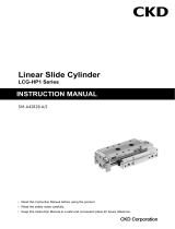
(1) AP11E4-15A 20A 25A
No. Part name Quantity No. Part name Quantity
1 Snap Ring 1 20
Valve Spring 1
2 Name Plate 1 21
Main Valve Assembly 1
3 Coil Cap 1 22
O ring 1
4 Waving Washer 1 23
Body 1
5 O ring 1 24
Hexagon Socket Bolt 1
6 Spacer 1 25
Washer 1
7 Coil Assembly 1 26
O ring 1
8 Coil Case 1 27
Crimp Style Terminal 3
9 Plunger
Assembly 1 28
Cross Recessed Screw
with Washer 6
10 O ring 1 29
Certified Label 1
11 Core Assembly 1 30
Terminal Cap 1
12 Holder 1 31
Terminal Case 1
13 Plunger Spring 1 32
O ring 1
14 O ring 1 33
Hexagon Socket Bolt 6
15 Tension Ring 1 34
Washer 6
16 Piston Ring 1 35
Hexagon Head Bolt with
Washer 4
17 Orifice Plate 1 36
Hexagon Socket Bolt 4
18 O ring 2 37
Washer 4
19 Stuffing 1
Model AP11E4
Earth
(Machine
Screw)
Earth
(Machine Screw)

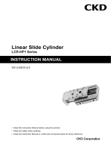
(2) AP11E2-15A 20A 25A (For steam)
No. Part name Quantity No. Part name Quantity
1 Snap Ring 1 21
Valve Spring 1
2 Name Plate 1 22
Rider Ring 1
3 Coil Cap 1 23
Main Valve Assembly 1
4 O ring 1 24
Gasket Guide 1
5 Waving Washer 1 25
Body 1
6 Spacer 1 26
Hexagon Socket Bolt 1
7 Coil Assembly 1 27
Washer 1
8 Coil Case 1 28
O ring 1
9 Plunger
Assembly 1 29
Crimp Style Terminal 3
10 O ring 1 30
Cross Recessed Screw
with Washer 6
11 Core Assembly 1 31
Certified Label 1
12 Holder 1 32
Terminal Cap 1
13 Plunger Spring 1 33
Terminal Case 1
14 O ring 1 34
O ring 1
15 Tension Ring 1 35
Hexagon Socket Bolt 6
16 Piston Ring 1 36
Washer 6
17 Gasket 2 37
Hexagon Head Bolt with
Washer 4
18 Orifice Plate 1 38
Hexagon Socket Bolt 4
19 O ring 1 39
Washer 4
20 Stuffing 1
Model:
A
P11E2
Earth
(Machine Screw)
Earth
(Machine
Screw)
Page is loading ...
Page is loading ...
Page is loading ...
Page is loading ...
Page is loading ...
Page is loading ...
Page is loading ...
Page is loading ...
/