Page is loading ...


Safety precautions
When designing and manufacturing a device using CKD products, the manufacturer is obligated
to manufacture a safe product by confirming safety of the system comprising the following items:
Device mechanism
Pneumatic or water control circuit
Electric control that controls the above
It is important to select, use, handle, and maintain the product appropriately to ensure that the
CKD product is used safely.
Observe warnings and precautions to ensure device safety.
Check that device safety is ensured, and manufacture a safe device.
This product is designed and manufactured as a general industrial machine part.
It must be handled by someone having sufficient knowledge and experience.
Use this product within its specifications.
Consult with CKD for details when using the product beyond the unique specification range,
outdoors, or in the following conditions or environment: Additionally, the product must not be
modified or machined.
Use for special applications requiring safety including nuclear energy, railroad, aviation,
ship, vehicle, medical equipment, equipment or applications coming into contact with
beverage or food, amusement equipment, emergency shutoff circuits, press machine,
brake circuits, or for safeguard.
Use for applications where life or assets could be adversely affected, and special safety
measures are required.
3 Observe corporate standards and regulations, etc., related to the safety of device
design and control, etc.
ISO4414, JIS B 8370 (pneumatic system rules)
JFPS2008(principles for pneumatic cylinder selection and use)
Including High Pressure Gas Maintenance Law, Occupational Safety and Sanitation Laws,
other safety rules, body standards and regulations, etc.
Do not handle, pipe, or remove devices before confirming safety.
Inspect and service the machine and devices after confirming safety of the entire system
related to this product.
Note that there may be hot or charged sections even after operation is stopped.
When inspecting or servicing the device, turn off the energy source (air supply or water
supply), and turn off power to the facility. Discharge any compressed air from the system,
and pay enough attention to possible water leakage and leakage of electricity.
When starting or restarting a machine or device that incorporates pneumatic components,
make sure that the system safety, such as pop-out prevention measures, is secured.
Observe warnings and cautions on the pages below to prevent accidents.

The safety cautions are ranked as "DANGER", "WARNING" and "CAUTION" in this
section.
When a dangerous situation may occur if handling is mistaken
leading to fatal or serious injuries, or when there is a high degree
of emergency to a warning.
When a dangerous situation may occur if handling is mistaken
leading to fatal or serious injuries.
When a dangerous situation may occur if handling is mistaken
leading to minor injuries or physical damage.
Note that some items described as "CAUTION" may lead to serious results depending on the
situation. In any case, important information that must be observed is explained.
Precautions with regard to guarantee
Guarantee period
The guarantee period of our product shall be one (1) year after it is delivered to the place
specified by the customer.
If any failure for which CKD CORPORATION is recognized to be responsible occurs within the
above warranty period, a substitute or necessary replacement parts shall be provided free of
charge, or the product shall be repaired free of charge at the plant of CKD CORPORATION.
However, the guarantee excludes following cases:
Defects resulting from operation under conditions beyond those stated in the catalogue or
specifications.
Failure resulting from malfunction of the equipment and/or machine manufactured by other
companies.
Failure resulting from wrong use of the product.
Failure resulting from modification or repairing that CKD CORPORATION is not involved in.
Failure resulting from causes that could not be foreseen by the technology available at the
time of delivery.
Failure resulting from disaster that CKD is not responsible of.
Guarantee stated here covers only the delivered products. Any other damage resulting from
failure of the delivered products is not covered by this guarantee.
Confirmation of product compatibility
Our customer shall be responsible of confirming compatibility of our product used in our
customer’s system, machinery or device.

Contents
1. Unpacking 4
2. Installation
2.1 Conditions for installation 4
2.2 Installation method 4
2.3 Piping method 5
2.4 Wiring method of the solenoid valve 8
2.5 Wiring method(With limit switch) 12
Pre-operation post-installation check
3.1 Appearance check 13
3.2 Check for leakage 13
3.3 Solenoid valve manual override 13
3.4 Electrical check of the solenoid valve 14
3.5 Electrical check (With limit switch) 14
4. Instructions for proper use
4.1 Precautions at use 15
4.2 About oil removal 16
4.3 Disassembly procedure 16
4.4 Assembly procedure 19
Maintenance
5.1 Maintenance and inspection 20
5.2 Service parts 20
6. Troubleshooting 21
7. Product specification and model number display method
2 port valve 23
3 port valve 25
8. Internal construction drawings
2 port valve internal construction drawings 27
3 port valve internal construction drawings 28

1. Unpacking
Do not remove the packing bag until just before piping work.
Otherwise, foreign matter enters from the port and cause
malfunction or bad operation.
(1) Check that the model No. shown on the face plate of the product is the same with what you
ordered.
(2) Check that the product has no external damages.
(3) When storing the product, attach a sealing plug to prevent the intrusion of foreign matter
to the valve. Remove the sealing plug when piping the valve.
2. Installation
Contact CKD if the product is to be used beyond
specifications, or in special applications.
2.1 Conditions for installation
a)
If there are high levels of dust in the area, provide
protection by installing a silencer or an elbow joint facing
downward onto the exhaust port so that dust does not
enter.
b) Do not use this product in an environment in which
corrosive gases could encroach the configuration materials.
c) Install this product at a place not subject to vibration.
d) Avoid humid environments, since condensation may occur
with change in temperature.
e) The coils will produce heat.
Particularly if the solenoid valve system is installed in a
control board or if the solenoid coils need to be energized
for a long time, consider providing sufficient ventilation to
release the heat. The coils can get very hot.
f) Where the ozone content is high, packing and gasket will
degrade fast. Such places include the following: near
seashore, or where lightning strikes often.
g) The solenoid valve mounted type must not be used
outdoors. Take appropriate measures to guard the valve if
it may be subject to water drip or oil, etc.
(1) When using the valve in a cold district, an proper provision is required to prevent freezing of
the valve.
(2) The solenoid valve mounted type cannot be used in an explosive gas atmosphere. To use in a
explosive gas atmosphere, install an explosion proof solenoid valve on the pilot air circuit of
the CHB, CHBF, CHG, CHB-R, CHBF-R or CHG-R series.
2.2 Installation method
2.2.1 Installation
a)
Always thoroughly read the Instruction Manual before
installing this product.
b) Always hold the body when handling or installing the
product.
c) After installing, check for leak from the pipe and make sure
that the product is correctly installed.
(1) The installation posture of the valve is not restricted.

2.2.2 Space for maintenance
An adequate space shall be provided around
the valve to assure the safety during the
maintenance / troubleshooting work.
(Figure 2.1)
2.3 Piping method
a)
Fix the product when tightening or reinstalling the piping.
When piping to the body side, fix the body, and when piping
to the cap side, fix the cap.
b) Fix and support the pipes so that the weight and vibration
of the pipes are not directly applied on the valves.
c) Torque required to tightening pipes are shown in Table 2.2,
2.3 for reference.
d) Do not plug the EXH port. Otherwise, pilot pressure cannot
be released and the valve does not operate.
(1) Cleaning of piping
Before piping, flush the inside of the pipe with 0.3MPa air, and remove any foreign matter,
metal powder, rust and sealing tape, etc.
(2) Removal of foreign matter
Any dirt or foreign matter in the fluid can prevent the product from functioning correctly.
Install an 80 mesh strainer when passing water, and a 5 or less filter when passing air.
(3) Piping
When piping, pipe the ball valve side and the supply port side of pilot air as shown in Table
2.1.
Fix the valve by piping support of the ball valve part.
When controlling the fluid in a tank, pipe at a level slightly above the bottom of the tank.

Table 2.1 Supply port
Actuation Ball valve side supply port Pilot air supply port
2port valve double acting A or B P
2port valve single acting A or B P
3port valve double acting C P
3port valve single acting C P
The following figure describes recommended piping methods.
Piping recommends the example of the following figure.
(Figure 2.2)
In order to make maintenance check easy to carry out, a union joint or a flange joint should
be used, as well as installation of a bypass.
(4) sealer
The sealer shall be used with great care to prevent it from entering the pipes or causing
external leakage.
When taping a threaded portion, 1 to 2 threads at the end of the portion shall be exposed.
(Figure 2.3 When using liquid sealer, take care not to apply too much sealer. Similarly to
the case of taping, threads at the end of the threaded portion shall be exposed.
Do not apply to the female screw of the product.
Seal tape Solid/liquid sealer
(Good) Not good Good Not good
(Figure 2.3)

(5) torque
Torque required to tightening pipes are shown in Table 2.2, 2.3 for reference
(6) Lubricated or non-lubricated operation
This series is used with pre-lubricated specifications, so no lubricator is required. Once
lubrication is started, however, lubricate continuously to avoid using up lubricator. When
lubricating, use the turbine Class 1/ISO VG32 (#90) or the equivalent.
(7) Provision for drain
The compressed air contains high levels of drain (water, oxidized oil, tar, foreign matter)
which can cause the reliability of the pneumatic components to drop remarkably. Improve
the quality of the air (create clean air) by removing moisture with an after cooler or dryer,
by removing the foreign matter with a filter, and by removing the tar with a tar removal
filter, etc.
(8) Solenoid valve for pilot operation
A 4-port valve (4KB119 made by CKD) is used as a solenoid valve for pilot operation.
Follow the specifications and usage of the valve when using the solenoid valve.
(Refer to the catalog “Pneumatic Valve” for details)
Table 2.2. Pilot port recommended torque
Port size Torque for tightening pipe
1 / 8 7 to 9 N m
Table2.3. Main port recommended torque
Port size Torque for tightening pipe
Rc3 / 8 31 to 33 N m
Rc1 / 2 41 to 43 N m
Rc3 / 4 62 to 65 N m
Rc1 83 to 86 N m
Rc1 / 97 to 100 N m
Rc1 / 104 to 108 N m
Rc2 132 to 136 N m

2.4 Wiring method of the solenoid valve
a)
C
onfirm the voltage and the alternating or direct current
type.
b) Permissible limit of leaked current
When operating the solenoid valve using a programmable
controller or equivalent, ensure that the leaked current
from the output line of the programmable controller will
not exceed the following level.
The leaked current may lead to a malfunction,(Figure 2.4)
Leak current : 3.0mA or less for the rated voltage AC100V
Leak current : 1.5mA or less for the rated voltage AC200V
Leak current : 1.8mA or less for the rated voltage DC24V
(Figure 2.4)
(1) Polarity of the solenoid valve
The valve does not have positive and negative terminals although it is designed for use with a
direct current.
It will not have polarity even if it is used with a lamp and/or a surge-absorber.
(2) Continuous power supply
When the solenoid valve is installed on a control panel or energized for an extended period, it
will be heated to a temperature of 40-60 . In this case, a provision is required to discharge
heat, i.e. ventilation.
(3) Surge in the electric circuit
In case your electric circuits hesitate the surge of solenoid, it is recommended to use our
surge-absorber provided valve or put a surge-absorber in parallel to the solenoid.
(4) The preservation of the electric facilities
Because of the preservation of the electric facilities, use breakers such as the fuse for the side
of the control circuit.
(5) When using the small terminal box and water-proof is required use cab-tire cords 4 to 6.5
in outer diameter (water-resistance is improved, but not for outdoor use)
(6) The connector type (C, C2, D, D2) should be used in a place with little dust and not directly
exposed to water and oil.
(7) For the electrical circuit, use a switching circuit free of chattering.
(8) Be sure that the operation voltage is within 10% of the rated voltage.
Leakage
current
Solenoid valve
Contact
Programmable
controller side
CR circuit

The surge suppressor enclosed with the solenoid valve is to
protect the output contact for that solenoid valve's drive. There is
no significant protection for other devices in the area, and the
surge may cause damage or malfunctions. Surge generated by
other devices could be absorbed and cause damage such as
burning. Note the followings when selecting the type with built-in
surge suppressor (coil option: L, C2, D2).
a) The surge suppressor limits solenoid valve surge voltage,
which can reach several hundred volts, to a lower voltage level
with standable by the output contact. Depending on the
output circuit used, this may be insufficient and could result
in damage or malfunction. Check whether the surge
suppressor can be used by the surge voltage limit of the
solenoid valve in use, the output device's withstand pressure
and circuit structure, and by the degree of return delay time.
If necessary, provide other surge measures. Solenoid valves
with surge suppressors suppress the reverse voltage surge
generated during OFF operation to the levels below.
b) When using the NPN output unit, a surge voltage equivalent
to the voltage above plus the power voltage surge could be
applied. Provide contact protection circuit.
c) If another device or solenoid valve is connected in parallel to
the solenoid valve, the inverse voltage surge generated when
the valve is OFF would apply to those devices. Even when
using the solenoid valve with surge suppressor for 24 VDC,
the surge voltage may reach minus several ten V depending
on the model. This inverse polarity voltage could damage or
cause the other devices connected in parallel to malfunction.
Avoid parallel connection of devices suspected of reversing
polarity voltages, e.g., LED indicators.
When driving several solenoid valves in parallel, the surge
from other solenoid valves could enter the surge suppressor of
one solenoid valve with a surge suppressor. Depending on the
current value, that surge suppressor could burn.
Even if the solenoid valve type is the same, the surge
suppressor's limit voltage can be inconsistent, and in the
worst case, could result in burning. Avoid parallel drive of a
solenoid valve of plurality.

d) The surge suppressor incorporated in the solenoid valve often
short circuits if damaged by overvoltage or overcurrent from a
source other than the solenoid valve. If the surge suppressor
fails, if a large current flows when output is on, the output
circuit or solenoid valve could be damaged or ignite. Do not
keep power on in a faulty state.
Provide an overcurrent protection circuit on the power or drive
circuit or use a power supply with overcurrent protection so
that a large current does not flow continuously.
2.4.1 Electric wire connection
Name Grommet (standard) Small terminal box Small terminal box
with lamp
Plug-in connector C type
with lead wire
Option
code No code B L C
Shape
Circuit
Note. DC is with surge
absorber.
Name
Plug-in connector C type
with lead wire, lamp
surge absorber
Plug-in connector D type
with lead wire
Plug-in connector D type
with lead wire, lamp
surge absorber
Option
code C2 D D2
Shape
Circuit
(Figure 2.5)
Lead wire
300mm
(11/0.16)
Lead wire
300mm
(11/0.16)
(
)
(
)
AC
(
)
(
)
DC
Red
Black
(
)
(
)
A
C
(
)
(
)
DC
Red
Black
Lead wire
300mm
(11/0.16)
Lead wire
300mm
(11/0.16)
Lead wire 300mm
(20/0.18)
90
(
)
(
)
DC
Red
Black
(
)
(
)
AC

2.4.2 Wiring of the small terminal box (B)
(Figure 2.6)
2.4.3 Wiring of the C-connector, D-connector, and small terminal box with lamp (L)
(Figure 2.7)

2.5 Wiring method (With limit switch)
(1) Wiring
When wiring screw terminals, use M3-size round solderless terminals with an insulation
tube is recommended.
The conductor size should be 0.75 mm2 and cable diameter should be 7 mm.
Figure 2.8 Figure 2.9
Round solderless terminals Wiring Method
Figure 2.8 Figure 2.9
If the one-touch connector is to be mounted onto the switch body, lightly push up the fitting
so that the switch body can then be inserted into the clamp. Figure 2.10
Figure 2.10
Be sure that the clamps are inserted to the full depth, because the Switch will not function
properly if one of the clamps is improperly inserted. Figure 2.11
Figure 2.11
If the clamps are properly inserted up to the full depth, it will not slide out easily.
Be sure to confirm all the above items.
The limit switch is D4E-1G20N made by OMRON Corporation.
Please refer to the catalogue of D4E-1G20N for the details.

3. Pre-operation post-installation check
3.1 Appearance check
(1) Push the valve with the finger to check that the valve has been properly fixed to the pipe.
(2) Check that the fasteners including hexagon socket head cap screws and bolts are not loose.
3.2 Check for leakage
(1) Apply pressure to the fluid to check for leakage at pipe joints.
It is recommended to check for leakage by supplying compressed air of 0.3 to 0.5MPa and
applying soap water to the joints. Air bubbles will appear at the leaking joints.
3.3 Solenoid valve manual override
(1) Manual operation (Non-lock type manual operation)
1) Supply compressed air (Double acting 0.35 to 0.7MPa, Single acting 0.4 to 0.7MPa) to
the pilot port.
2) Push the manual shaft until it bottoms. The valve will be energized while the manual
shaft is pushed. The valve will return when the manual shaft is released.
(See Figure 3.1)
Name Non-lock type manual operation
Shape
Keeps on activation during the
time this button is pushed
Figure 3.1
Shut off the fluid flow.(Close the main shut-off valve)
Exhaust the fluid remaining in the valve.
PUSH

3.4 Electrical check of the solenoid valve
Turn off the power supply.
Do not touch the wiring connection sections (bare live part) when
energized. There is a risk of electric shock.
(1) Check the dielectric resistance.
Measure the dielectric resistance using a 100V DC megohmmeter between a metallic part
such as screw fixing the valve and the active part of the lead. The measured dielectric
resistance shall be 100Mohms or more.
(2) P Check the supply voltage.
The voltage fluctuation shall be within ±10% of the rated voltage.
Usage in a out range of allowable voltage cause a mis-operation or coil burning.
(3) When changing a line voltage.
This product carries the solenoid valve “4KB119 00” of our company. When you change
voltage, Exchange 4KB119 00. Please refer to an exclusive catalog about 4KB119 00.
3.5 Electrical check (With limit switch)
Turn off the power supply.
Do not touch the wiring connection sections (bare live part) when
energized. There is a risk of electric shock.
(1) Please refer to Table 3.1 for the rating.
Table 3.1. Ratings
(2) Power supply shall be more than 0.8W. Contact faults may occur if a Switch for
general-load is used to switch a micro load circuit.
(3) Values above show normal current.
(4) Light load refers to a load with 10-fold rush current.
(5) The maximum rush current is 10 A.
(6) Consult with CKD when using at extremely small loads.
(7) The limit switch is D4E-1G20N made by OMRON Corporation. Please refer to the
catalogue of D4E-1G20N for the details.
Rated
voltage
Non-inductive load (A)
Resistive load Lamp load
NC NO NC NO
250VAC 5 1.5
30VDC 5

4. Instructions for proper use
Precautions at use
a) Do not use this product for an emergency shut off valve.
The valves listed in this catalog are not designed as
valves to ensure safety such as emergency shut off valves.
When using in this type of system, always take separate
measures that will absolutely ensure safety.
b) Take measures to prevent harm to operators or objects if
this product fails.
c) Don’t touch the electric wiring part while it is energized.
There is fear of the electric shock.
d) Liquid-filled state
When conveying a liquid in a circuit, operation may fail if
liquid-filled state occurs. This is because pressure rises
in the liquid filled state when temperature changes.
e) Working fluids
Do not use this product for fluids other than the working
fluids listed in the specifications.
Before starting use, confirm the compatibility of the
product and applicable fluid with the catalog Applicable
Fluid Check List.
Internal parts may wear when the valve operates.
Caution is required because wear chips could enter the
secondary side of the valve.
a) Observe the working pressure range.
b) Water hammer prevention
When preventing water hammer, restrict the exhaust side
with metering valve with silencer and flow control valve,
etc.
c) Failure to observe the cycle rate could shorten service life.
d) Do not touch the stem on the top of the actuator when
activated.
e) Generally, the valve can be used with a fluid viscosity of up
to 500mm2/s. However, the properties may differ according
to the fluid type, so consult with CKD.
Observe the pressurization direction (C-port pressurization
limit) for the 3 port valve.
(1) Do not put any object on the valve.
(2) The working pressure range and temperature range of the fluid and ambient temperature
range shall be satisfied.
(3) Do not use this product in a explosive gas atmosphere.(applies only for products with limit
switch)
(4) Perform trial run if the product has not been used for a long time.
(5) Refer to “6. Troubleshooting” if any abnormality occurs.
(6) Life could be shortened when using dry air (atmospheric dew point -20°C or less) at AC
voltage. Using DC voltage with dry air is recommended. Consult with CKD when using AC
voltage.

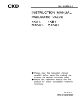
4.2 About oil removal
In CKD, high quality oil removal is attained by the following assembling procedures.
Take care when handling the product.
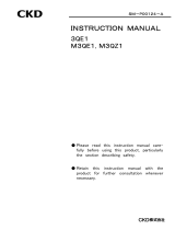
4.3 Disassembly procedure
Close the main supply valve and stop fluid flow.
Exhaust the fluid remaining in the valve.
(1) Before disassembly, release the pilot and fluid pressure.
Confirm that there is no residual pressure inside the product.
(2) Remove the hexagon socket head cap screw or the hexagon bolt .
Then , remove the spring washer .
(3) Raise the actuator upwards.
Part name Quantity
Actuator Assembly
Ball valve
Spring washer
Hexagon socket head cap screw( 1)
Hexagon bolt( 2)
1 CHB V 10 to 25 CHB X 10 to 20
CHBF V 15 to 20 CHBF X 15
CHG V 15 to 25 CHG X 15 to 20
2 CHB V 32 to 50 CHB X 25 to 50
CHBF V 25 to 40 CHBF X 20 to 40
CHG V 32 to 50 CHG X 25 to 50
Part store
Part washing
Dry air is used, Concentration of oil
at the secondary side is 0.1 mg/m3
or less
Shipment
Inspection
Conveyance
Assembly
Packing
(No oil and grease are used.)
(The whole product is wrapped in a
plastic bag and are put in a packing
box.
)
Dustproof room
Figure 4.1 The exploded view of the
actuator and the ball valve

Do not disassemble the actuator.
Press-fitted parts are used for the actuator. It is not reusable
once it is taken off.
Do not disassemble the single acting type actuator section.
Incorporated reinforced spring will pop out when
disassembled.
a) Do not disassemble the product if the body material is
bronze.
Adhesives are applied to the connection part of the body
and the cap. Once removed, external leak occurs from the
connection part.
b) When the ball valve is “oil removal type”, the product cannot
be disassembled.
Since a high non-oil level is maintained, the
composition parts of a ball valve are not exchangeable.
Exchange the whole ball valve.
1) Disassembly of the ball valve (When the body material is stainless steel)
(1) Set the ball valve to the closed position.
(2) Firmly fix the opposite sides of the octagon shape of the valve body . Remove the valve
cap with a tool such as an adjustable spanner. Take out the valve ball and the O ring
. Replace the valve ball and the O ring if there are any sign of defects or corrosion.
(3) Take out the respective valve sheets and O rings from the valve body and the valve
cap. Replace the valve seat and O ring if there are any sign of defects, corrosion or
permanent distortion. It is recommended to replace the valve seat once it is disassembled,
since re-used valve seats may leak internally.
(4) Take out the shaft from the body .
Replace the O ring if there are any sign of defects corrosion or permanent distortion.
Replace the spacer if abrasion loss is large.
Figure 4.2 Ball valve exploded view
Part name Quantity
Oring
Spacer
Shaft
Valve body
Valve cap
Valve ball
Valve seat
Oring
Oring

Disassembly of the solenoid valve kit
Models excluding CHB X 40 to 50, CHBF X 32 to 40, CHG X 40 to 50
(1) Remove the cross recessed head machine screw . Then, pull up the solenoid valve and
the gasket .
(2) Loosen the hexagon socket head cap screw . Then, remove the block and the O ring .
Models CHB X 40 to 50, CHBF X 32 to 40, CHG X 40 to 50
(1) Remove the cross recessed head machine screw . Then, pull up the solenoid valve and
the gasket .
(2) Loosen the hexagon socket head cap screw . Then, remove the block and the O ring
.
(3) Loosen the cross recessed countersunk head machine screw . Then, remove the plate
and the O ring .
Figure 4.3 Solenoid valve kit exploded view
Please refer to instruction manual of 4KB119 00 about decomposition of a solenoid valve.
No. Parts name Quantity
14 Cross recessed head machine screw 2
15 Solenoid valve 4KB119 00 1
16 Gasket 1
17 Hexagon socket head cap screw 4
18 Block 1
19 O ring 2
20 O ring 2
21 Cross recessed countersunk head machine screw 4
22 Plate 1

3) Disassembly of the limit switch (option)
(1) Take off the cross recessed head cap screw .
(2) Remove the limit switch .
4.4 Assembly procedure
1) The assembly of the solenoid valve kit
Models excluding CHB X 40 to 50, CHBF X 32 to 40, CHG X 40 to 50
(1) Apply lithium grease or silicone grease to the O ring .
Recommended lithium grease Idemitsu Kosan Co., Ltd. Daphne Eponex Grease No.1
Recommended silicone grease Shin-Etsu Chemical Co., Ltd. Shin-Etsu silicone G 30H
(2) Set the O ring to the block .
(3) Attach the block to the actuator using the hexagon socket head cap screw .
Tightening torque of the hexagon socket head cap screw 0.6 to 0.8N .
(4) Attach the solenoid valve and the gasket to the block using the cross recessed
head machine screw .
Models CHB X 40 to 50, CHBF X 32 to 40, CHG X 40 to 50
(1) Apply lithium grease or silicone grease to the O ring .
(2) Set the O ring to the plate .
(3) Attach the plate to the actuator using the cross recessed countersunk head
machine screw .
Tightening torque of the cross recessed countersunk head machine screw 1.5 to 1.9 N .
(4) Set the O ring to the plate .
(5) Attach the block to the actuator using the hexagon socket head cap screw .
Tightening torque of the hexagon socket head cap screw 0.6 to 0.8 .
(6) Attach the solenoid valve and the gasket to the block using the cross recessed
head machine screw .
2) Assembly of the ball valve (When the body material is stainless steel)
(1) Apply silicone grease to the O ring .
Recommended silicone grease Shin-Etsu Chemical Co., Ltd. Shin-Etsu silicone G 30H
(2) Set the O ring and the spacer to the shaft .
Set the O ring certainly to the O ring groove on the shaft.
(3) Apply silicone grease to the part on which the shaft slides, and set the shaft to the valve
body.
(4) Set the O ring and the valve seat to the valve body and the valve cap one
piece each.
No. Parts name Quantity
23 Limit switch D4E-1G20N 2 1
24 Cross recessed head screw
with captive washer
4 2
25 LS plate 1
Quantity described in ( ) is when there is one
limit switch for detection at valve open (H) and
detection at valve closed (V).
Figure 4.4 Limit switch exploded view
/