Page is loading ...

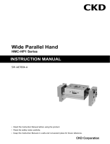
INSTRUCTION MANUAL
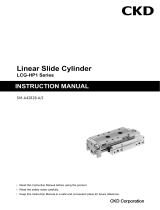
Linear Slide Cylinder
LCR-HP1 Series
SM-A10603-A/3
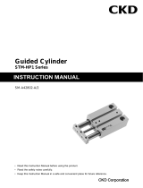
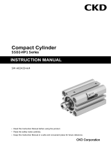
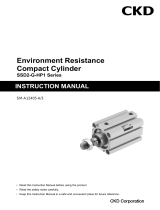
• Read this Instruction Manual before using the product.
• Read the safety notes carefully.
• Keep this Instruction Manual in a safe and convenient place for future reference.

SM-A10603-A/3 PREFACE
i 2022-06-27
PREFACE
Thank you for purchasing CKD's "LCR-HP1 Series" Linear Slide Cylinder.
This Instruction Manual contains basic matters such as installation and usage instructions in order to
ensure optimal performance of the product. Please read this Instruction Manual thoroughly and use the
product properly.
Keep this Instruction Manual in a safe place and be careful not to lose it.
Product specifications and appearances presented in this Instruction Manual are subject to change
without notice.
• The product is intended for users who have basic knowledge about materials, piping, electricity,
and mechanisms of pneumatic components. CKD shall not be responsible for accidents caused
by persons who selected or used the product without knowledge or sufficient training.
• Since there are a wide variety of customer applications, it is impossible for CKD to be aware of all
of them. Depending on the application or usage, the product may not be able to exercise its full
performance or an accident may occur due to fluid, piping, or other conditions. It is the
responsibility of the customer to check the product specifications and decide how the product shall
be used in accordance with the application and usage.

SM-A10603-A/3 SAFETY INFORMATION
ii 2022-06-27
SAFETY INFORMATION
When designing and manufacturing any device incorporating the product, the manufacturer has an
obligation to ensure that the device is safe. To that end, make sure that the safety of the machine
mechanism of the device, the fluid control circuit, and the electric system that controls such mechanism
is ensured.
To ensure the safety of device design and control, observe organization standards, relevant laws and
regulations, which include the following:
ISO 4414, JIS B 8370, JFPS 2008 (the latest edition of each standard), the High Pressure Gas
Safety Act, the Industrial Safety and Health Act, other safety rules, organization standards, relevant
laws and regulations
In order to use our products safely, it is important to select, use, handle, and maintain the products
properly.
Observe the warnings and precautions described in this Instruction Manual to ensure device safety.
Although various safety measures have been adopted in the product, customer's improper handling
may lead to an accident. To avoid this:
Thoroughly read and understand this Instruction Manual
before using the product.
To explicitly indicate the severity and likelihood of a potential harm or damage, precautions are
classified into three categories: "DANGER", "WARNING", and "CAUTION".
DANGER
Indicates an imminent hazard. Improper handling will cause death or
serious injury to people.
WARNING
Indicates a potential hazard. Improper handling may cause death or serious
injury to people.
CAUTION
Indicates a potential hazard. Improper handling may cause injury to people
or damage to property.
Precautions classified as "CAUTION" may still lead to serious results depending on the situation.
All precautions are equally important and must be observed.
Other general precautions and tips on using the product are indicated by the following icon.
Indicates general precautions and tips on using the product.

SM-A10603-A/3 SAFETY INFORMATION
iii 2022-06-27
Precautions on Product Use
WARNING
The product must be handled by a qualified person who has extensive knowledge and
experience.
The product is designed and manufactured as a device or part for general industrial machinery.
Use the product within the specifications.
The product must not be used beyond its specifications. Also, the product must not be modified
and additional work on the product must not be performed.
The product is intended for use in devices or parts for general industrial machinery. It is not
intended for use outdoors or in the conditions or environment listed below.
• In applications for nuclear power, railroad system, aviation, ship, vehicle, medical equipment,
and equipment that directly touches beverage or food.
• For special applications that require safety including amusement equipment, emergency shut-
off circuit, press machine, brake circuit, and safety measures.
• For applications where life or properties may be adversely affected and special safety
measures are required.
(Exception is made if the customer consults with CKD prior to use and understands the
specifications of the product. However, even in that case, safety measures must be taken to
avoid danger in case of a possible failure.)
Do not handle the product or remove pipes and devices until confirming safety.
• Inspect and service the machine and devices after confirming the safety of the entire system.
Also, turn off the energy source (air supply or water supply) and power to the relevant facility.
Release compressed air from the system and use extreme care to avoid water or electric
leakage.
• Since there may be hot or live parts even after operation has stopped, use extreme care when
handling the product or removing pipes and devices.
• When starting or restarting a machine or device that incorporates pneumatic components,
make sure that a safety measure (such as a pop-out prevention mechanism) is in place and
system safety is secured.
Precautions on Product Disposal
CAUTION
When disposing of the product, comply with laws pertaining to disposal and cleaning of
wastes and have an industrial waste disposal company dispose of the product.

SM-A10603-A/3 CONTENTS
iv 2022-06-27
CONTENTS
PREFACE ........................................................................................................................... i
SAFETY INFORMATION .................................................................................................. ii
Precautions on Product Use .......................................................................................... iii
Precautions on Product Disposal .................................................................................. iii
CONTENTS ...................................................................................................................... iv
1. PRODUCT OVERVIEW ............................................................................................. 1
1.1 Model Number Indication .................................................................................... 1
Product model number ................................................................................... 1
Stopper model No. selection method ............................................................. 4
Switch model No. ........................................................................................... 7
How to order a stopper set ............................................................................. 7
How to order discrete stopper bracket ........................................................... 8
How to order discrete stroke adjusting stopper ............................................. 9
How to order discrete shock absorber stopper ............................................ 10
How to order discrete stopper block............................................................. 10
Model No. of plug kit for side piping port .......................................................11
1.2 Specifications .................................................................................................... 12
Product specifications .................................................................................. 12
Switch specifications .................................................................................... 13
2. INSTALLATION ....................................................................................................... 16
2.1 Environment ...................................................................................................... 16
2.2 Unpacking ......................................................................................................... 17
2.3 Mounting ........................................................................................................... 17
Mounting the Body ....................................................................................... 17
Mounting the switch ...................................................................................... 19
Changing the position of the switch ............................................................. 21
Replacing the switch .................................................................................... 21
2.4 Piping ................................................................................................................ 22
Piping port .................................................................................................... 24
2.5 Wiring ................................................................................................................ 26
Proximity switch ............................................................................................ 26
Reed switch .................................................................................................. 29
3. USAGE ..................................................................................................................... 31
3.1 Using the Cylinder............................................................................................. 31
3.2 Using the Switch ............................................................................................... 32
4. MAINTENANCE AND INSPECTION ....................................................................... 33
4.1 Periodic Inspection............................................................................................ 34
Inspection item ............................................................................................. 34
Maintenance of the product .......................................................................... 34
Maintenance of the circuit ............................................................................. 34
4.2 Disassembly method,Assembly method .......................................................... 35
Disassembly method ..................................................................................... 35
Assembly method .......................................................................................... 35
Internal structural diagram............................................................................ 36
5. TROUBLESHOOTING............................................................................................. 38
5.1 Problems, Causes, and Solutions .................................................................... 38
Cylinder ........................................................................................................ 38
Switch ........................................................................................................... 39

SM-A10603-A/3 CONTENTS
v 2022-06-27
6. WARRANTY PROVISIONS ..................................................................................... 40
6.1 Warranty Conditions ......................................................................................... 40
6.2 Warranty Period ................................................................................................ 40

SM-A10603-A/3 1. PRODUCT OVERVIEW
1 2022-06-27
1. PRODUCT OVERVIEW
1.1 Model Number Indication
Product model number
◼ Example of model number indication:LCR-HP1 series
Note 1:For the port position, refer to the
stopper dimensions in "Pneumatic
Cylinders II (No.CB-030SA)".
Note 2:Can be selected for the type with
stopper only.
Note 3:Refer to the selection table on page
4 to 6 for combinations of options.
Note 4:Select when using rear piping.
Note 5:Cannot be selected when choosing
two-sided combined type (W).

SM-A10603-A/3 1. PRODUCT OVERVIEW
2 2022-06-27
◼ Example of model number indication:LCR-P4※-HP1 series
Note1: For the port position, refer to the stopper
dimensions in "Pneumatic Cylinders II
(No.CB-030SA)".
Note2: Can be selected for the type with stopper
only.
Note3: Refer to the selection table on page 4 to
6 for combinations of options.
Note4: Select when using rear piping.
Note5: Cannot be selected when choosing two-
sided combined type (W).
Note6: Even when P40 is selected for the
external stopper option, electrolytic
nickel plating is used for the stopper part.

SM-A10603-A/3 1. PRODUCT OVERVIEW
3 2022-06-27
◼ (E)Stopper
Code
Stopper installation position
Brank
No stopper Note 6
S Stroke adjusting stopper Note 2
S1※※
Stopper position①(can be changed to ④)
S2※※
Stopper position②(can be changed to ③)
S3※※
Stopper position③(can be changed to ②) Note 7
S4※※
Stopper position④(can be changed to ①) Note 7
S5※※
Stopper position①,③
S6※※
Stopper position②,④
A Stopper position Note 1,2
A1
Stopper position①(can be changed to④)
A2
Stopper position②(can be changed to③)
A3
Stopper position③(can be changed to②) Note 7
A4
Stopper position④(can be changed to①) Note 7
A5
Stopper position①,③
A6
Stopper position②,④
W Both-sided combined double stopper (shock absorber stopper,metal stopper) Note 4,5
W1
A1+metal stopper
W2
A2+ metal stopper
W3
A3+metal stopper
W4
A4+ metal stopper
W5
A5+ metal stopper
W6
A6+ metal stopper
C One side hybrid stopper mix (shock absorber stopper,stroke adjusting stopper)
C1※※
A1+S3
C2※※
A2+S4
C3※※
A3+S1
C4※※
A4+S2
※※part Adjustable stroke range ●Compatible with all. ▲Compatible with some. Note 3
Protruding end
Return end
Stopper model No.
S
A
W
C
Blank
5mm or none
5mm or none
●
-
-
●
02
15mm or none
15mm or none
●
●
03
25mm or none
25mm or none
●
●
04
15mm
5mm
▲
-
05
25mm
5mm
▲
-
06
5mm
15mm
▲
-
07
5mm
25mm
▲
-
Note1:For the adjustable stroke range with a shock absorber stopper, refer to the stopper dimensions table in "Pneumatic Cylinders II
(No. CB-030SA)".
Note2:Refer to stoppers “C*” and “W*” for combination of the stroke adjusting stopper and shock absorber type stopper.
Note3:Can be selected only when using stroke adjusting stopper (S) and one side mixed type (C).
Note4:When two switches are necessary or a switch is installed on the head side of W3 to 6 (both-sided combined stopper) of ø6 (all
stroke lengths), ø8 with 20 or 30 mm stroke length, ø12 with 30 to 50 mm stroke length or ø16 with 30 to 50 mm stroke
length,select the lead wire straight type.
Note5:The adjustable stroke range when choosing both-sided combined use (W) is ø6: 9 mm, ø8: 13.5 mm, ø12: 14.5 mm, ø16: 15 mm,
ø20: 13 mm, ø25: 10 mm.
Note6:The port positions of the standard without stopper are ① and ③ .
Note7:When changing the stopper position from the head side to the rod side, the stopper must be purchased separately according to
the stroke length and adjustable stroke length. Refer to "Precautions when purchasing discrete stopper" on page 9.
A1, A2 and adjustable stroke length of 15 mm and 25 mm may not be available depending on the stroke length.
A1**, A2**, A5** and A6** of ø6 to ø8 with 10 mm stroke length or less and ø12 to ø25 with 20 mm stroke length or less are
made to order since they are not adjustable using the standard stopper.
When two switches are necessary for the type with S*** or A*** of ø6 to ø8 with 30 mm stroke length or less,
select the F□H type switch.
The stroke adjusting stopper for 0.3 MPa and over working pressure is the metal sealing type.

SM-A10603-A/3 1. PRODUCT OVERVIEW
4 2022-06-27
Stopper model No. selection method
◼ (A)Shock absorber stopper,(W)Two-sided combined double stopper
Model No.-[①Stopper model No.]+[②Stopper position Model No.]
Example)LCR-12-40-F2H-R-[A][1]-HP1
▲ shows the piping direction.
If two-sided combined type (W) is selected, the stopper bracket comes with piping on both
sides, ▲ (piping direction) and the reverse side stopper bracket comes with a plug.
<Selection table>
The table above also applies to combinations with option code D (with port on stopper) or T
(steel stopper block (nitriding)).

SM-A10603-A/3 1. PRODUCT OVERVIEW
5 2022-06-27
◼ (S)Stroke adjusting stopper
Model No.-[①②Stopper model No.]+[③Adjustable stroke range model No.]
Example)LCR-8-40-[S5][06]-HP1
▲ shows the piping direction.
<Selection table>
The table above also applies to combinations with option code D (with port on stopper) or T
(steel stopper block (nitriding)).

SM-A10603-A/3 1. PRODUCT OVERVIEW
6 2022-06-27
◼ (C)One side hybrid stopper mix
Model No.-[①②Stopper model No.]+[③Adjustable stroke range model No.]
Example)LCR-12-40-[C2][03]-HP1
• ▲ shows the piping direction.
• For the adjustable stroke range for a shock absorber stopper, refer to the stopper
dimensions table in "Pneumatic Cylinders II (No. CB-030SA)".
<Selection table>
The table above also applies to combinations with option code D (with port on stopper) or T
(steel stopper block (nitriding)).

SM-A10603-A/3 1. PRODUCT OVERVIEW
7 2022-06-27
Switch model No.
< Switch body only>
Switches for P4 * series have different order model numbers from the standard ones.
Please refer to "Equipment related to rechargeable batteries P4* Series"(No.CC-1226A).
How to order a stopper set
Please contact CKD for P40.
• Set of a stopper and stroke adjusting stopper or shock absorber stopper
• Use it when changing from the standard to the stroke adjusting stopper or shock absorber stopper
Note1:When installing in the stopper mounting position ① or ②,
the stroke causes changes in the adjustable stroke length;see the next page.
Note2:ø6 and ø8 are not available for S03.
Note3:Cannot be selected for the shock absorber stopper "A".
Bottom port is plug-sealed.
When using the bottom port with ø20 and 25,buy a plug kit (LCR-20-N 2 pieces/set) and seal
the side surface ports before using.

SM-A10603-A/3 1. PRODUCT OVERVIEW
8 2022-06-27
◼ Precautions when purchasing the stopper set
When the stopper set is installed in the mounting position ① or ②(refer to page 3),note that the
adjustable stroke length will be as shown on the below according to the stroke length.
Model No.
Opition code
Discrete stroke adjusting stopper
Adjustable stroke length (mm)
Bore size
Stroke
length
-5
-15
-25
LCR Series
φ6,φ8
10
S02
-
-
20 or more
Blank
S02
-
φ12 to φ25
10
S03
-
-
20
S02
S03
-
30 or more
Blank
S02
S03
-:Not applicable
Stopper set weight (unit:g)
Stopper type
S1,S2
A1,A2
Port on the stopper
Blank,D
Adjustable stroke
length
Blank
S02
S03
Blank
φ6
15
18
-
18
φ8
21
25
-
27
φ12
28
31
34
33
φ16
42
47
52
49
φ20
77
85
92
86
φ25
87
94
101
95
How to order discrete stopper bracket
Please contact CKD for P40.
Used when changing between □1 (□3) and □2 (□4) or when changing to the stopper with port.
※ □: S,A
Stopper bracket weight (Unit: g)
Stopper installation
position
1,2
Port on the stopper
Blank, D
φ6
8
φ8
14
φ12
20
φ16
29
φ20
53
φ25
62
Bottom port is plug-sealed.
When using the bottom port with ø20 and 25, buy a plug kit (LCR-20-N 2 pieces/set) and seal
the side surface ports before using.

SM-A10603-A/3 1. PRODUCT OVERVIEW
9 2022-06-27
How to order discrete stroke adjusting stopper
• Hexagon socket set screw with urethane
• Use when changing the adjustable stroke range or when using a custom stroke length.
Specify S01, S02 or S03 in A.
S03 is not available for ø6 and ø8.
Some models may not be available and adjustable stroke range may differ from the above
depending on the Model No.
◼ Precautions when purchasing discrete stopper
When a discrete stroke adjusting stopper or a discrete shock absorber stopper is installed in the ① or
② position (refer to page 3), the combination will be as shown on the below according to the stroke
length and adjustable stroke length.
Model No.
Option code
Discrete stroke adjusting stopper
Discrete shock
absorber
stopper
Adjustable stroke length (mm)
Bore size
Stroke length
-5
-15
-25
LCR Series
-S1, S2, S5, S6
-A1, A2, A5, A6
φ6,φ8
10
S02
-
-
-
20 or more
S01
S02
-
A01
φ12 to φ25
10
S03
-
-
-
20
S02
S03
-
-
30 or more
S01
S02
S03
A01
-:Not available
Discrete stroke adjusting stopper weight (Unit: g)
Adjustable stroke
range
S01
S02
S03
φ6
6
9
-
φ8
7
10
-
φ12
7
11
14
φ16
11
16
22
φ20
22
30
37
φ25
23
30
37

SM-A10603-A/3 1. PRODUCT OVERVIEW
10 2022-06-27
How to order discrete shock absorber stopper
Please contact CKD for P40.
• Shock absorber set
• Use when changing from the stroke adjusting stopper to the shock absorber stopper
• Some models may not be available depending on the specifications.
• For the adjustable stroke range for a shock absorber stopper, refer to the stopper
dimensions table in "Pneumatic Cylinders II (No. CB-030SA)".
Applicable shock absorber model No.
Model
Shock absorber model No.
Weight (g)
LCR-6-HP1
SKL-0804
9
LCR-8-HP1
SKL-0805
12
LCR-12-HP1
SKL-0805
12
LCR-16-HP1
SKL-1006
19
LCR-20-HP1
SKL-1208
31
LCR-25-HP1
SKL-1208
31
How to order discrete stopper block
Please contact CKD for P40.
• Use it when changing from the standard to the stroke adjusting stopper or shock absorber stopper.
Discrete stopper block weight (Unit: g)
Block
SB1(T)
SB2(T)
φ6
11
21
φ8
14
24
φ12
23
37
φ16
38
72
φ20
60
99
φ25
112
206

SM-A10603-A/3 1. PRODUCT OVERVIEW
11 2022-06-27
Model No. of plug kit for side piping port
Weight of plug kit for side piping port
Bore size
Weight (g)
φ8
1
φ12
1
φ16
1
φ20
5

SM-A10603-A/3 1. PRODUCT OVERVIEW
12 2022-06-27
1.2 Specifications
Product specifications
Model
LCR-HP1
LCR-P4※-HP1
Descriptions
Bore size mm
φ6
φ8
φ12
φ16
φ20
φ25
Actuation
Double acting
Working fluid
Compressed air
Max. working pressure MPa
0.7
Min. working pressure MPa
0.15 Note 1
Proof pressure MPa
1.05
Ambient temperature °C
-10 to 60 (no freezing)
Port size
Main body side
M3
M5
Rc1/8
Main body back
-
M3
M5
Rc1/8
Stroke tolerance mm
Note 2
Working piston speed mm/s
50 to 500 Note 3
Cushion
With rubber cushion
Lubrication
Not required
Note 1: 0.2Mpa when using φ6 shock absorber stopper.
Note 2: Note that there will be a slight gap between the end plate and floating bush if no stopper is attached.
Note 3: Keep within 50 to 200 mm/s when using a stroke adjusting stopper.
※ The stroke adjusting stopper for 0.3 MPa and over working pressure is the metal sealing type.
+2.0
0

SM-A10603-A/3 1. PRODUCT OVERVIEW
13 2022-06-27
Switch specifications
Descriptions
Reed 2-wire type
T0H/V
T5H/V
Applications
For programmable controller, relay
For programmable controller,
relay, IC circuit(without indicator),
serial connection
Power supply voltage
―
Load voltage
12/24 VDC
110 VAC
5/12/24 VDC
110 VAC
Load current
5 mA to 50 mA
7 mA to 20 mA
50 mA or less
20 mA or less
Current consumption
―
Internal voltage drop
3 V or less (For DC, when the load current is 30mA)
0.1 V or less (Internal resistance 0.5Ω or less)
Indicator
Red LED (Lights up when turned on)
―
Leakage current
―
Lead wire Note 1
Standard is 1 m (Oil-resistant vinyl cabtyre 2 core cord, 0.2 mm2)
Shock resistance
294m/s2
Insulation resistance
20 MΩ or more with 500 VDC megger
Withstand voltage
No abnormality after applying 1000 VAC for one minute
Ambient temperature
−10°C to 60°C
Degree of protection
IP 67 (IEC standard), JIS C 0920 (watertight), oil-resistant
Descriptions
Proximity
2-wire type
3-wire type
F2S/H/V
F2YH/V
F3S/H/V
F3YH/V
Applications
Only for programmable controller
For programmable controller, relay
Power supply voltage
―
10 to 28VDC
Load voltage
10 to 30VDC
24VDC±10%
30 VDC or less
Load current
5 to 20mA Note 2
50 mA or less
Current consumption
―
10 mA or less at 24 VDC
Internal voltage drop
4V or less
0.5V or less
Indicator
Yellow LEDNote 3
(Lights up when turned
on)
Red/green LED
(Lights up when turned
on)
Yellow LED Note 3
(Lights up when turned
on)
Red/green LED
(Lights up when turned
on)
Leakage current
1 mA or less
10 μA or less
Lead wire Note 1
Standard is 1 m
(Elasticity,Oil-resistant vinyl cabtyre 2 core cord,
0.15 mm2)
Standard is 1 m
(Elasticity,Oil-resistant vinyl cabtyre 3 core cord,
0.15 mm2)
Shock resistance
980m/s2
Insulation resistance
20 MΩ or more with 500 VDC megger
Withstand voltage
No abnormality after applying 1000 VAC for one minute
Ambient temperature
−10°C to 60°C
Degree of protection
IP 67 (IEC standard), JIS C 0920 (watertight), oil-resistant

SM-A10603-A/3 1. PRODUCT OVERVIEW
14 2022-06-27
Descriptions
Proximity
2-wire type
3-wire type
T2H/V
T2WH/V
T3H/V
T3WH/V
Applications
Only for programmable controller
For programmable controller, relay
Power supply voltage
―
10 to 28VDC
Load voltage
10 VDC to 30 VDC
24VDC±10%
30VDC or less
Load current
5 mA to 20 mA Note 2
100 mA or less
50 mA or less
Current consumption
―
10 mA or less at 24 VDC
Internal voltage drop
4 V or less
0.5V or less
Indicator
Red LED
(Lights up when turned
on)
Red/green LED
(Lights up when turned
on)
Red LED
(Lights up when turned
on)
Red/green LED
(Lights up when turned
on)
Leakage current
1 mA or less
10μA or less
Lead wire Note 1
Standard is 1 m (Oil-resistant
vinyl cabtyre 2 core cord, 0.2 mm2)
Standard is 1 m (Oil-resistant
vinyl cabtyre 3 core cord, 0.2 mm2)
Shock resistance
980m/s2
Insulation resistance
20 MΩ or more with 500 VDC megger
Withstand voltage
No abnormality after applying 1000 VAC for one minute
Ambient temperature
−10°C to 60°C
Degree of protection
IP 67 (IEC standard), JIS C 0920 (watertight), oil-resistant
Descriptions
Proximity 3-wire type
T3PH/V
F3PH/V
Applications
For programmable controller, relay
Power supply voltage
10 to 28 VDC
4.5 to 28VDC
Load voltage
30 VDC or less
Load current
100mA or less
50mA or less
Current consumption
10 mA or less at 24 VDC
10 mA or less at 24 VDC
Internal voltage drop
0.5V or less
0.5 V or less at 30 mA
Indicator
Yellow LED (Lights up when turned on)
Leakage current
10μA or less
Lead wire Note 1
Standard is 1 m
(Oil-resistantvinyl cabtyre 3 core cord, 0.2 mm2)
Standard is 1 m
(Elasticity,Oil-resistant vinyl cabtyre 3 core cord, 0.15
mm2)
Shock resistance
980m/s2
Insulation resistance
20 MΩ or more with 500 VDC megger
Withstand voltage
No abnormality after applying 1000 VAC for one minute
Ambient temperature
−10°C to 60°C
Degree of protection
IP 67 (IEC standard), JIS C 0920 (watertight), oil-resistant
/