Page is loading ...

SM-
SM-SM-
SM-50519
5051950519
50519-A
-A-A
-A
INSTRUCTION
INSTRUCTIONINSTRUCTION
INSTRUCTION MANUAL
MANUALMANUAL
MANUAL
3
33
3-
--
-PORT, SOLENOID
PORT, SOLENOID PORT, SOLENOID
PORT, SOLENOID VALVE
VALVEVALVE
VALVE
NP13
NP13NP13
NP13 Series
Series Series
Series
NP14
NP14NP14
NP14 Series
Series Series
Series
Please
PleasePlease
Please
read
readread
read
this
thisthis
this
instruction
instructioninstruction
instruction
manual
manualmanual
manual
carefully
carefullycarefully
carefully
before
beforebefore
before
using
usingusing
using
this
thisthis
this
product,
product,product,
product,
particularly
particularlyparticularly
particularly
the
thethe
the
section
sectionsection
section
describing
describingdescribing
describing
safety
safetysafety
safety.
..
.
Retain
RetainRetain
Retain
this
thisthis
this
instruction
instructioninstruction
instruction
manual
manualmanual
manual
with
withwith
with
the
thethe
the
product
productproduct
product
for
forfor
for
f
ff
further
urtherurther
urther
consultation
consultationconsultation
consultation
whenever
wheneverwhenever
whenever
necessary
necessarynecessary
necessary.
..
.
Ver.2
Ver.2Ver.2
Ver.2

SM-
SM-SM-
SM-50519
5051950519
50519-A
-A-A
-A
-1-
Safety precautions
When designing and manufacturing a device using CKD products, the manufacturer is obligated
to manufacture a safe product by confirming safety of the system comprising the following items:
Device mechanism
Pneumatic or water control circuit
Electric control that controls the above
It is important to select, use, handle, and maintain the product appropriately to ensure that the
CKD product is used safely.
Observe warnings and precautions to ensure device safety.
Check that device safety is ensured, and manufacture a safe device.
1
11
1.
..
.This product is designed and manufactured as a general industrial machine part.
This product is designed and manufactured as a general industrial machine part.This product is designed and manufactured as a general industrial machine part.
This product is designed and manufactured as a general industrial machine part.
It must be handled by someone having sufficient knowledge and experience.
It must be handled by someone having sufficient knowledge and experience. It must be handled by someone having sufficient knowledge and experience.
It must be handled by someone having sufficient knowledge and experience.
2
22
2.
..
.Use this product within
Use this product within Use this product within
Use this product within its
itsits
its specifications.
specifications. specifications.
specifications.
Consult with CKD for details when using the product beyond the unique specification range,
outdoors, or in the following conditions or environment: Additionally, the product must not be
modified or machined.
① Use for special applications requiring safety including nuclear energy, railroad, aviation,
ship, vehicle, medical equipment, equipment or applications coming into contact with
beverage or food, amusement equipment, emergency shutoff circuits, press machine,
brake circuits, or for safeguard.
② Use for applications where life or assets could be adversely affected, and special safety
measures are required.
3
33
3.
..
. Observe corporate standards and regulations, etc., related to the safety of device
Observe corporate standards and regulations, etc., related to the safety of device Observe corporate standards and regulations, etc., related to the safety of device
Observe corporate standards and regulations, etc., related to the safety of device
design and control, etc.
design and control, etc.design and control, etc.
design and control, etc.
ISO4414, JIS B 8370 (pneumatic system rules)
JFPS2008(principles for pneumatic cylinder selection and use)
Including High Pressure Gas Maintenance Law, Occupational Safety and Sanitation Laws,
other safety rules, body standards and regulations, etc.
4
44
4.
..
.Do not handle, pipe, or remove devices before confirming safety.
Do not handle, pipe, or remove devices before confirming safety.Do not handle, pipe, or remove devices before confirming safety.
Do not handle, pipe, or remove devices before confirming safety.
① Inspect and service the machine and devices after confirming safety of the entire system
related to this product.
② Note that there may be hot or charged sections even after operation is stopped.
③ When inspecting or servicing the device, turn off the energy source (air supply or water
supply), and turn off power to the facility. Discharge any compressed air from the system,
and pay enough attention to possible water leakage and leakage of electricity.
④ When starting or restarting a machine or device that incorporates pneumatic components,
make sure that the system safety, such as pop-out prevention measures, is secured.
5
55
5.
..
.Observe warnings and cautions on the pages below to prevent accidents.
Observe warnings and cautions on the pages below to prevent accidents.Observe warnings and cautions on the pages below to prevent accidents.
Observe warnings and cautions on the pages below to prevent accidents.
WARNING
WARNINGWARNING
WARNING

SM-
SM-SM-
SM-50519
5051950519
50519-A
-A-A
-A
-2-
■
■■
■
The safety cautions are ranked as "DANGER", "WARNING" and "CAUTION" in this
The safety cautions are ranked as "DANGER", "WARNING" and "CAUTION" in this The safety cautions are ranked as "DANGER", "WARNING" and "CAUTION" in this
The safety cautions are ranked as "DANGER", "WARNING" and "CAUTION" in this
section.
section.section.
section.
:
::
:When a dangerous situation may occur if handling is mistaken
leading to fatal or serious injuries, or when there is a high degree
of emergency to a warning.
:
::
:When a dangerous situation may occur if handling is mistaken
leading to fatal or serious injuries.
:
::
:When a dangerous situation may occur if handling is mistaken
leading to minor injuries or physical damage.
Note that some items described as "CAUTION" may lead to serious results depending on the
situation. In any case, important information that must be observed is explained.
Precautions
Precautions Precautions
Precautions with regard to guarantee
with regard to guaranteewith regard to guarantee
with regard to guarantee
Guarantee period
Guarantee periodGuarantee period
Guarantee period
The guarantee period of our product shall be one (1) year after it is delivered to the place
specified by the customer.
Guarantee coverage
Guarantee coverageGuarantee coverage
Guarantee coverage
If any falure for which CKD CORPORATION is recognized to be responsible occurs within the
above warranty period, a substitute or necessary replacement parts shall be provided free of
charge, or the product shall be repaired free of chargeat the plant of CKD CORPORATION.
However, the guarantee excludes following cases:
① Defects resulting from operation under conditions beyond those stated in the catalogue or
specifications.
② Failure resulting from malfunction of the equipment and/or machine manufactured by other
companies.
③ Failure resulting from wrong use of the product.
④ Failure resulting from modification or repairing that CKD CORPORATION is not involved in.
⑤ Failure resulting from causes that could not be foreseen by the technology available at the
time of delivery.
⑥ Failure resulting from disaster that CKD is not responsible of.
Guarantee stated here covers only the delivered products. Any other damage resulting from
failure of the delivered products is not covered by this guarantee.
Confirmation of product compatibility
Confirmation of product compatibilityConfirmation of product compatibility
Confirmation of product compatibility
Our customer shall be responsible of confirming compatibility of our product used in our
customer’s system, machinery or device.
DANGER
DANGERDANGER
DANGER
WARNING
WARNINGWARNING
WARNING
CAUTION
CAUTIONCAUTION
CAUTION

SM-
SM-SM-
SM-50519
5051950519
50519-A
-A-A
-A
-3-
【
【【
【
Contents
ContentsContents
Contents
】
】】
】
1.
1.1.
1.
Unpacking
UnpackingUnpacking
Unpacking
…………………… 4
2.
2.2.
2.
Installation
InstallationInstallation
Installation
2.1 Conditions for installation …………………… 4
2.2 Installation method …………………… 5
2.3 Piping method …………………… 6
2.4 Wiring method …………………… 8
3.
3. 3.
3. Pre
PrePre
Pre-
--
-operation
operation operation
operation (
((
(post
postpost
post-
--
-installation
installationinstallation
installation)
))
) check
check check
check
3.1 Appearance check …………………… 12
3.2 Check for leakage …………………… 12
3.3 Electrical check …………………… 12
4.
4. 4.
4. Instructions for proper use
Instructions for proper useInstructions for proper use
Instructions for proper use
4.1 Precautions at use …………………… 13
4.2 Disassembly and assembly procedure of the solenoid valve for pilot
operation …………………… 14
4.3 Disassembly and assembly procedure of the Valve Stem
…………………… 16
5
55
5.
. .
. Maintenance
MaintenanceMaintenance
Maintenance
5.1 Maintenance and inspection ……………………… 17
5.2 Service parts ……………………… 17
6
66
6.
. .
. Troubleshooting
TroubleshootingTroubleshooting
Troubleshooting
……………………… 18
7
77
7.
. .
. Operating mechanism
Operating mechanismOperating mechanism
Operating mechanism
7.1 Specifications for the product No. ……………………… 19
7.2 Specifications for the product ……………………… 20
8.
8. 8.
8. Internal construction drawings
Internal construction drawingsInternal construction drawings
Internal construction drawings
……………………… 21

SM-
SM-SM-
SM-50519
5051950519
50519-A
-A-A
-A
-4-
1. Unpacking
Do not remove the packing bag until just before piping work.
Otherwise, foreign matter enters from the port and cause
malfunction or bad operation.
(1) Check that the model No. shown on the face plate of the product agrees with that you
ordered.
(2) Check that the product has no external damages.
(3) When storing the product, attach a sealing plug to prevent the intrusion of foreign matter
to the valve. Remove the sealing plug when piping the valve.
2. Installation
Contact CKD if the product is to be used beyond
specifications, or in special applications.
2.1 Conditions for installation
a) Do not splash fluids such as water or cutting oil directly.
・Fluids (such as water or cutting oil) splashed onto the coil
part of the pilot solenoid valve causes the coil to burn.
b) Coil generates heat.
・If the product will be installed in a control panel, of if the
product will be energized for a long time, provide measures
such as ventilation to release heat. The product
temperature will be high.
c) The product cannot be used in a corrosive or solvent
atmosphere.
d) Avoid using the product in a humid atmosphere, since
change in temperature may cause bedewing.
e) The product cannot be used in an explosive gas atmosphere.
f) Prevent dust from entering the valve interior.
・If there are high levels of dust in the area , provide
protection by installing a silencer or an elbow joint facing
downward onto the exhaust port so that dust does not
enter.
g) Use the product away from radiant heat.
(1) When using the valve in a cold district, an proper provision is required to prevent freezing of
the valve.
(2) This product cannot be used outdoors. Protect the product by a cover or by installing it in
a panel.
(3) After the product is installed, avoid washing or painting the product using water or
solvents. Otherwise, resin parts may break.
(4) Do not subject this product to vibration or inertia.
CAUTION
CAUTIONCAUTION
CAUTION
WARNING
WARNINGWARNING
WARNING
WARNING
WARNINGWARNING
WARNING

SM-
SM-SM-
SM-50519
5051950519
50519-A
-A-A
-A
-5-
2.2 Installation
2.2.1 Installation
a) Always thoroughly read the Instruction Manual before
installing this product.
b) Always hold the body when handling or installing the
product.
c) After installing, check for leak from the pipe and make sure
that the product is correctly installed.
(1) The mounting posture of the valve is not specified.
(2) Fix the valve using the mounting hole on the valve except when using a metallic pipe.
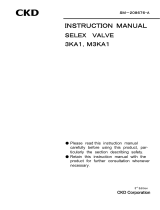
2.2.2 Space for maintenance
・An adequate space shall be provided around the valve to assure the safety during the
maintenace/troubleshooting work (see Figure 2-1).
(Figure 2.1)
CAUTION
CAUTIONCAUTION
CAUTION
Space for overhauling
300 or more
Mounting hole Mounting hole
Pipe Pipe
Space for overhauling
300 or more

SM-
SM-SM-
SM-50519
5051950519
50519-A
-A-A
-A
-6-
2.3 Piping method
a) Fix the product when tightening or reinstalling the piping.
When piping to the body side, fix the body, and when piping
to the cap side, fix the cap.
b) Fix and support the pipes so that the weight and vibration
of the pipes are not directly applied on the valves.
c)
Torque required to tightening pipes are shown in Table 2-1 for
reference
.
(1) Cleaning the pipes
・Before piping, flush the inside of the pipe with 0.3MPa air, and remove any foreign matter,
metal powder, rust and sealing tape, etc.
(2) Removal of foreign matter
・Dust and foreign matter within the fluid causes the valve to malfunction and leak. Install a
filter 5μm or finer at the primary side of the valve.
・The rusting of the inside of the pipes may lead to a malfunction and/or leakage.
(3) Prevention of dust being mixed
・If the valve is used in the atmosphere containing much dust, it will be likely to malfunction
or cause a leakage.
・In this case, a silencer or filter shall be installed at the exhaust or air intake port to prevent
the intrusion of dust.
(4) Flowing direction of the fluid
・The valve shall be piped in such a manner that the flowing direction of the fluid will match
the direction of the arrow indicated on the JIS symbol of the product.
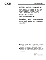
(5) Sealer
・The sealer shall be used with great care to prevent it from entering the pipes or leaking out.
・When taping a threaded portion, one or two threads at the end of the portion shall be exposed
(see Figure 2-2).
・When using liquid sealer, take care not to apply too much sealer. Similarly to the case of
taping, one or two threads at the end of the threaded portion shall be exposed (see Figure 2-3).
・Do not apply to the female screw of the apparatus.
(Figure 2.2) (Figure 2.3)
(Good)
(Not good)
CAUTION
CAUTIONCAUTION
CAUTION
●Seal type
●Solid/liquid sealer
S
olid/liquid
sealer
S
olid/liquid
sealer
(Good)
(Not good)

SM-
SM-SM-
SM-50519
5051950519
50519-A
-A-A
-A
-7-
(6) Torques required for tightening pipes
・The torques required for tightening pipes are shown in Table 2-1 for reference.
Table 2-1. Recommended values of the torques for tightening pipes
Nominal size of pipe Torque for tightening pipe
Rc 1/8 7 - 9 [ N ・ m ]
Rc 1/4 12 - 14 [ N ・ m ]
Rc 3/8 22 - 24 [ N ・ m ]
Rc 1/2 28 - 30 [ N ・ m ]
Rc 3/4 31 - 33 [ N ・ m ]
Rc 1 36 - 38 [ N ・ m ]
Rc 1 1/4 40 - 42 [ N ・ m ]
Rc 1 1/2 48 - 50 [ N ・ m ]
Rc 2 54 - 56 [ N ・ m ]
(7) Lubricated or unlubricated operation
・This valve does not require lubrication. Therefore, no lubricator is needed.
・If the valve is to be lubricated, use type 1 turbine oil, ISO VG 32 (no additives).
(8)
Minimum differential pressure
・A differential pressure of 0. 2 MPa or more is required for the valve to operate.
・If the sectional area of the pipe at the fluid supply port is too small, the valve operation may
become instable due to the insufficient differential pressure.
・For the fluid supply port, use a pipe of the size that fits the inside diameter of the connector
port of the valve.
(9) Provision for drain
・ The compressed air contains high levels of drain (water, oxidized oil, tar, foreign matter)
which can cause the reliability of the pneumatic components to drop remarkably. Improve
the quality of the air (create clean air) by removing moisture with an after cooler or dryer,
by removing the foreign matter with a filter, and by removing the tar with a tar removal
filter, etc.

SM-
SM-SM-
SM-50519
5051950519
50519-A
-A-A
-A
-8-
2.4 Wiring method
(1) Continuous power supply
・When the solenoid valve is installed on a control panel or energized for an extended period,
it will be heated to a temperature. In this case, a provision is required to discharge heat, i.e.
ventilation.
(2) Permissible limit of leaked current
・When operating the solenoid valve using a programmable controller or equivalent, ensure
that the leaked current from the output line of the programmable controller will not exceed
the following level (see Figure 2-4). ---Leaked current: 1.8 (3) mA or less
The leaked current may lead to a malfunction.
The value within parentheses represents the leaked current measured with a surge killer
provided.
(Figure 2-4)
(3) Polarity of the solenoid valve
・The valve does not have positive and negative terminals although it is designed for use with
a direct current. It will not have polarity even if it is used with a lamp and/ or surge killer.
2.4.1 Electric connection of grommet coil lead
This subsection applies to the one with grommet coil (optional coil code “2C”).
(1)
The lead shall be connected using a crimped terminal or sleeve specially
designed for copper leads.
(2)
If there is a possibility of leaked electricity at the electric connection, it shall
be adequately insulated.
Programmable controller
Triac
CR circuit
Leaked
current
Solenoid valve
C
R

SM-
SM-SM-
SM-50519
5051950519
50519-A
-A-A
-A
-9-
2.4.2 Electric connection of DIN terminal box
This subsection applies to the ones with DIN terminal box (optional coil code “2G” or “2H”).
(1) For the cabtire cord, use the one specified in Table 2-2.
Table 2-2
Connection port size of valve
Specifications for cabtire cord 10A - 25A 32A - 50A
O.D. of cord φ4.5 – φ7 φ6-φ10
Nominal sectional area mm
2
0.75 0.75-1.5
(2) Pass a cap, washer, gasket and casing through the cabtire cord.
(3) Pass a crimped terminal specially designed for copper leads through the lead of the cabtire
cord and crimp the terminal.
(4) Fix the crimped terminal on the terminal block.
(5) Enclose the terminal block with the casing.
(6) Tighten the cap to fix the cabtire cord so that it will not come off.
(7) Insert the DIN terminal box to the coil with the grounding terminal of the coil aligned with
that on the terminal block.
Take care not to connect the terminal box in a wrong manner.
The terminals with markings ① and ② on the terminal block
are for conductors.
The terminal with a marking GND on the terminal block is for
grounding.
CAUTION
CAUTIONCAUTION
CAUTION

SM-
SM-SM-
SM-50519
5051950519
50519-A
-A-A
-A
-10-
( Figure 2-5. ) Electric connection of DIN terminal box (10A to 25A)
( Figure 2-6. ) Electric connection of DIN terminal box (32A to 50A)
●
DIN terminal box (Pg 9)
● DIN terminal box with lamp (Pg 9)
●
DIN termina
l box (Pg 11)
● DIN terminal box with lamp (Pg 11)
Cover with case and tighten with set screw
・Insert the cap , washer , gasket and case.
・Tighten the cable with the cap.
Peel lead wire sheath
Insert gasket and gland into coil terminal
Ground cable
Coil assembly
Ground terminal
Gasket
Voltage terminal
Gland
Note:
+/- classification
not required
Case
Set screw
Washer
Cap
Gasket
Terminal caulking
Bare crimp terminal for copper wire
Fix crimp terminal
onto gland
Cabtire cable
JIS C3306 VCTF 0.75m
2
Outside diameter φ4.5 to7
Note:
Can be ro
tated 180
°
Cover with case and tighten with set screw
Case
Set screw
Peel lead wire sheath
Ground cable
Gasket
Terminal caulking
Bare crimp terminal for copper wire
Washer
Cap
Cabtire cable
JIS C3306 Core wire 0.75 to 1.5 m
2
Outside diameter φ6 to 10
Insert gasket and gland into coil terminal
Ground terminal
Gland
Gasket
Voltage terminal
Coil assembly
Fix crimp terminal onto
gland
・the orientation of the
cable lead out port can be
changed by removing the
gland from the case ,
rotating it by 180°, and
then replacing the gland
into the case.
・the orientation of the cable lead out port
can be changed by removing the gland
from the case , rotating it by 90°, and
then replacing the gland into the case.
Note:
Can be rotated 90
°
Note:
+/- classification not required
・Insert the cap , washer , gasket and case.
・Tighten the cable with the cap.

SM-
SM-SM-
SM-50519
5051950519
50519-A
-A-A
-A
-11-
2.4.3 Electric connection of T-type terminal box
This subsection applies to the ones with T-type terminal box (optional coil code “3T” or “3R”).
(1) For the cabtire cord, use the one with a nominal sectional area ranging from 0.75 to 1.5 mm
2
.
(2) Pass the cabtire cord to the terminal box.
(3) Pass a crimped terminal specially designed for copper leads through the lead of the cabtire
cord and crimp the terminal.
(4) Fixing racket the Crimp Terminal by tightening the Free terminal Screw with tightening
torque of 0.5Nm.
(5) After overlaying the Gasket and Cap Assembly, tighten the Set Screw with tightening torque
of 0.5Nm.
●T-type terminal box ( G1/2 )
●T-type terminal box with lamp ( G1/2 )
( Figure 2-7 ) Electric connection of T-type terminal box
Bare crimp terminal for copper wire
JIS C2805 R1.25
-
3
Free termi
nal screw
Conduit coil
Terminal box
main body
Fixing racket
Coil l
ead wire
Lock
nut
Set
screw
Gasket
Cap ass
embly

SM-
SM-SM-
SM-50519
5051950519
50519-A
-A-A
-A
-12-
3. Pre-operation (post-installation) check
3.1 Appearance check
(1) Push the valve with finger to check that the valve has been fixed to the pipe or mounting
hole.
(2) Check that the fasteners including hexagonal socket head cap screws and bolts have not
been loosened.
3.2 Check for leakage
(1) Compress the fluid to check for leakage at pipe joints.
It is recommended to check for leakage by supplying a pneumatic pressure of 0.3 - 0.5 MPa
with soapy water applied to the joints. Air bubbles will be generated at the leaking joints.
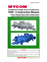
(2) Manual operation
①Compress the fluid.
②Push the manual shaft until it bottoms.
The valve will be energized while the
manual shaft is pushed. The valve will
return when the manual shaft is
released.
(See Figure 3-1.)
The valve operates while the shaft is pushed.
( Figure 3-1.)
3.3 Electrical check (With limit switch)
Turn off the power supply.
Do not touch the wiring connection sections (bare live part) when
energized. There is a risk of electric shock.
(1) Check the dielectric resistance.
Measure the dielectric resistance using a 1,000 VDC megaohmmeter between a metallic
part such as screw fixing the valve and the active part of the lead. The measured
dielectric resistance shall be 100 Mohms or more.
(2) Check the supply voltage.
The voltage variation shall be within ±10% of the rated voltage.
(3) If the time for which the valve is energized is too short, the valve may not follow the
operation of the entire system.
Check that the operating frequency specified in section 10 is satisfied
(4) If the valve has been out of use for seven days or longer, the first cycle after the restart of
the valve may take approximately a second longer than usual.
In this case, a commissioning shall be performed before operating the valve.
Shut off the fluid flow.
Exhaust the fluid remaining in the valve.
Turn off the power.
WARNING
WARNINGWARNING
WARNING
WARNI
WARNIWARNI
WARNI
NG
NGNG
NG

SM-
SM-SM-
SM-50519
5051950519
50519-A
-A-A
-A
-13-
4. Instructions for proper use
4.1 Precautions at use
a) Do not use this product for an emergency shut off valve.
・The valves listed in this catalog are not designed as
valves to ensure safety such as emergency shut off valves.
When using in this type of system, always take separate
measures that will absolutely ensure safety.
b) Take measures to prevent harm to operators or objects if
this product fails.
c) Liquid-filled state
・ When conveying a liquid in a circuit, operation may fail if
liquid-filled state occurs. This is because pressure rises
in the liquid filled state when temperature changes.
d) Working fluids
・ Do not use this product for fluids other than the working
fluids listed in the specifications.
・ Before starting use, confirm the compatibility of the
product and applicable fluid with the catalog Applicable
Fluid Check List.
・ Internal parts may wear when the valve operates.
Caution is required because wear chips could enter the
secondary side of the valve.
b) When the solenoid valve is continuously operated, it will be
heated to a temperature.
Do not touch it by hand while it is energized.
c) If there is a possibility that the operator may trip on a
power cable, it may lead to an accident. Protect the power
cable using a conduit or equivalent.
d) Install a silencer at the exhaust port of the main piping to
the valve to reduce the noise to be given to the personnel
working around the machine.
(1) Do not put any object that weighs 1 kgf or more on the valve.
(2) The voltage variation shall be within ±10% of the rated voltage.
(3) The operating frequency specified below shall be satisfied.
Table 4-1. Operating frequency
Connection port size of valve Operating frequency
10A・15A 360 cycles/min or less
20A・25A 180 cycles/min or less
32A・50A 90 cycles/min or less
If the time for which the valve is energized is too short, the valve may not follow the
operation of the entire system.
(4) If the valve has been out of use for seven days or longer, the first cycle after the restart of
the valve may take approximately a second longer than usual.
In this case, a commissioning shall be performed before operating the valve.
(5) Periodically remove the drain accumulated in the air filter.
(6) If the filter element of the air filter turns black, it means that it has been contaminated
with tar. Periodically clean the filter element.
(7) When supplying oil using a lubricator, periodically replenish oil to keep the oil level in the
lubricator.
For lubrication, use type 1 turbine oil, ISO VG 32 (no additives).
(8) If any abnormal condition is found, see section “Troubleshooting.”
WARNING
WARNINGWARNING
WARNING
CAUTION
CAUTIONCAUTION
CAUTION

SM-
SM-SM-
SM-50519
5051950519
50519-A
-A-A
-A
-14-
4.2 Procedures for disassembling and assembling solenoid actuator section
4.2.1 Disassembly procedure
a) Close the main valve.
b) Exhaust the fluid remaining in the valve.
Turn off the power.
(1) Remove wires from the solenoid valve.
(2) Loosen the screw.
(3) Raise the solenoid valv e.
.
(Figure 4-1 )
( Figure 4-2 ) Developed view of the pilot solenoid valve ( 10A to25A )
CAUTION
CAUTIONCAUTION
CAUTION
Note 1:
When disassembling the
solenoid valve, take case not to
lose the manual depressor pin.
Note 2: When assembling the
solenoid valve, take care not to
install the gasket in the wrong
direction.
Note 3: Different coil assemblies
and plungers are used for AC
voltage and for DC voltage.
Replace the coil assembly and
plunger as a unit.
Note 4: Turbine oil is applied to
the plunger for lubrication.
Screw
Solenoid valve
G
asket (see Note 2)
Manual depressor pin
(see Note 1)
S
pring
G
asket (see Note 2)
NC body
NO body assembly
O ring
Plunger
(see
Note 4
)
Plunger spring
Coil assembly
(see Note 3)
Screw
V
alve plate assembly

SM-
SM-SM-
SM-50519
5051950519
50519-A
-A-A
-A
-15-
( Figure 4-3 ) Developed view of the pilot solenoid valve ( 32A to50A )
4.2.2
Assembly procedure
(1) Install the gasket to the body assembly with care not to install it in the wrong direction.
(2) Put the solenoid valve on the stauffing. Take care not to orient the manual unit in a wrong
way.
(3) Tighten the screw.
Table 4-2. Torques required for tightening
(4) Connect electric wires to the valve.
(5) Turn on the power and activate the fluid.
( Figure 4-4 )
Size of screw Torque required for tightening
M3 0.7 - 1.1N・m
M4 1.1 – 1.8N・m
Note 1:
Take care not to install
the gasket in the wrong direction.
Manual shaft
Staffing
Screw
Coil assembly
S
pring
Gasket
(see Note 1)
B
ody assembly
O ring
Plunger assembly

SM-
SM-SM-
SM-50519
5051950519
50519-A
-A-A
-A
-16-
4.3 Procedures for disassembling and assembling valve stem
4.3.1 Disassembly procedure
a) Close the main valve。
b) Exhaust the fluid remaining in the valve.
c) Turn off the power.
(1) Loosen the hexagon socket head cap
screw on the stauffing.
(2) Raise the stauffing.
(3) Loosen the hexagon socket head cap
screw on the cap.
At this time, take care not to lose
the spring located inside the cap.
( Figure 4-5 )
4.3.2 Assembly procedure
(1) The assembly shall be performed with reference to section 8 “Internal construction
drawings.”
(2) Apply grease to the packing and O ring.
For grease, use silicone grease G-40H, Shinetsu Kagaku Kogyo.
(3) Apply grease to the surface on which the piston slides.
(4) Apply grease to the surfaces of the body and valve seat on which the packing slides.
(5) Insert the valve stem from the bottom of the body.
(6) Insert the valve seat from the bottom of the body.
(7) Install the gasket, piston, spring and cap and tighten the hexagon socket head cap screw.
At this time, the holes on the gasket shall be aligned with the body and cap respectively.
(8) Install the stauffing and tighten the hexagon socket head cap screw. Again, take care to
correctly locate the holes on the gasket.
(9) Compress the fluid to check that the fluid is not leaking out.
(10) Turn on the power and activate the fluid circuit.
CAUTION
CAUTIONCAUTION
CAUTION
Hexagon soket
head cap screw
Cap
Staffing
Hexagon soket
head cap screw

SM-
SM-SM-
SM-50519
5051950519
50519-A
-A-A
-A
-17-
5.Maintenance
5.1 Maintenance and inspection
(1) To keep the product in the good condition, inspect it twice a year unless otherwise
specified.
(2) For the content of the inspection, see section 3 “Pre-operation check.”
5.2 Service parts
(1) Solenoid valve
Replace the solenoid valve with a new one if an electric failure or another abnormal
condition is observed with it.
As a guideline, replace it every 10 million cycles.
(2) Valve stem, valve seat and spring
Replace them with new ones if fluid leaks or the valve seat does not move or delays to move
during the operation.
As a guideline, replace them every 10 million cycles.
(3) Packing, O ring and gasket
Replace them with new ones if fluid leaks or another abnormal condition is observed.
As a guideline, replace them every 10 million cycles.

SM-
SM-SM-
SM-50519
5051950519
50519-A
-A-A
-A
-18-
6.Troubleshooting
If the valve does not function as specified, check it according to Table 6-1.
Table 6-1
Symptom Cause Action
It is not energized. Check the wiring and fuse and turn
on the power supply.
The voltage is lower than the rating. Check the power supply and apply
the rated voltage.
The fluid pressure is too low. Adjust the pressure.
Too large a pressure drop during the
operation.
The sectional area of the pipe at the
fluid supply port is too small. Use
a pipe of the size that fits the valve.
The pilot solenoid valve does not move. Replace the pilot solenoid valve
with a new one.
Foreign matter is entangled by the
valve stem.
Overhaul the valve and clean the
inside of it.
The valve does
not move.
The gasket has been installed in the
wrong direction.
Overhaul and reassemble the valve.
It is not de-energized. Check for leaked current. Modify
the circuit to turn off the power
supply without fail.
The pilot solenoid valve does not
return.
Replace the pilot solenoid valve
with a new one.
Foreign matter is entangled by the
valve stem.
Overhaul the valve and clean the
inside of it.
The gasket has been installed in the
wrong direction.
Overhaul and reassemble the valve.
The valve does
not return.
Packing is running short of grease. Overhaul and reassemble the valve.
The fluid pressure is too high. Adjust the pressure.
The packing is damaged or worn. Overhaul the valve and replace the
packing with a new one.
External
leakage
O ring is damaged. Overhaul the valve and replace the
O ring with a new one.
The valve seat on the body is damaged.
Replace the body with a new one.
The sealing surface of the valve seat is
damaged.
Replace the valve seat with a new
one.
The rubber or sealing surface of the
valve stem is damaged or worn.
Replace the valve stem with a new
one.
Leakage from
the valve seat
Foreign matter is entangled by the
valve stem.
Overhaul and clean the valve.
※If further information is required, consult us or the nearest agency.

SM-
SM-SM-
SM-50519
5051950519
50519-A
-A-A
-A
-19-
7.Specifications for the product
7.1 Meaning of the model No.
/