OVAL ALTI mass CA080 Instructions Manual
- Category
- Measuring, testing & control
- Type
- Instructions Manual

Every OVAL product is fabricated, tested, and inspected under stringent quality control before it
leaves our factory.
To derive maximum benefit from the product, we recommend you to be well familiar with the
information and instructions given in this manual before you place it in service and retain this
manual at the field location for ready reference.
ALTI
mass
■ Type U/Sophisticated models: CA00A, CA001, CA003, CA006, CA010, CA015
CA025, CA040, CA050, CA080, CA100, CA150
CA15H, CA200, CA20H, CA250
■ Type S/Straight tube models: CS010, CS015, CS025, CS040, CS050, CS080
CSR50
■ Type B/Low price, general purpose models:
CB006, CB010, CB015, CB025, CB040, CB050
■ Transmitter : PA0K
1
Ins. No. L-740-28-E
Type S Type B
Separately mounted
transmitter
Type U
Large size
Type U
Extra low flows
Type U
Type U
Low flows

L--740--28--E
CONTENTS
1. BEFORE YOU BEGIN ............................................................................................................ 5
1.1 Confirming the Tag Information ............................................................................................. 5
1.2 Transportation Guidelines ..................................................................................................... 5
1.3 Storage Guidelines ................................................................................................................ 5
1.4 Precautions for Operating Conditions ................................................................................... 6
1.5 Precautions for Installation Location ..................................................................................... 6
1.6 Precautions for power-on ...................................................................................................... 6
1.7 Returning Equipment ............................................................................................................. 6
2. GENERAL AND FEATURES ................................................................................................ 7
2.1 General Description ............................................................................................................... 7
2.2 Features ................................................................................................................................ 7
3. SPECIFICATIONS AND PERFORMANCE ........................................................................ 7
3.1 Sensor Unit General Specifications ........................................................................................ 7
3.1.1 Type U sensor unit general specifications ....................................................................... 7
3.1.2 Type S sensor unit general specifications ..................................................................... 11
3.1.3 Type B sensor unit general specifications ..................................................................... 11
3.1.4 Transmitter general specifications .................................................................................. 12
3.1.5 Max. operating temperature of PED specification .......................................................... 12
3.2 General Performance ........................................................................................................... 13
3.2.1 Type U general performance .......................................................................................... 13
3.2.2 Type S general performance ........................................................................................... 16
3.2.3 Type B general performance ........................................................................................... 16
3.3 Display .................................................................................................................................. 17
4. PRESSURE LOSSES ............................................................................................................ 17
4.1 Type U Pressure Losses ...................................................................................................... 17
4.2 Type S Pressure Losses ........................................................................................................19
4.3 Type B Pressure Losses ........................................................................................................20
5. PART NAMES AND OUTLINE DIMENSIONS .................................................................. 21
5.1 Type U ................................................................................................................................... 21
5.1.1 CA00A, CA001 and CA003 (separately mounted models).............................................. 21
5.1.2 CA006 thru CA080 (integrally mounted models) ............................................................. 22
5.1.3 CA100 thru CA250 (integrally mounted models) ............................................................. 24
5.1.4 CA006 thru CA080 (separately mounted models) ........................................................... 25
5.1.5 CA100 thru CA250 (separately mounted models) ........................................................... 27
5.1.6 High temperature service models (CA025 to CA150) .....................................................28
5.1.7 Low temperature explosionproof service models (CA025 to CA080) .............................. 29
5.1.8 Low temperature explosionproof service models (CA100 to CA250) .............................. 30
5.1.9 Ferrule fitting type (integrally and separately mounted models,
low temperature explosionproof service models) ............................. 34
5.2 Type S ...................................................................................................................................33
5.2.1 Stainless steel tube type (integrally and separately mounted models)............................ 33
5.2.2 Titanium tube type (integrally and separately mounted models) ..................................... 34
5.2.3 Ferrule fitting type (integrally and separately mounted models) ...................................... 35
5.3 Type B ...................................................................................................................................36
5.3.1 Integrally mounted models ............................................................................................. 36
5.3.2 Separately mounted models ........................................................................................... 37
5.4 Separately Mounted Transmitter ...........................................................................................38
6. INSTALLATION .......................................................................................................................38
6.1 Installation Guidelines .......................................................................................................... 38
6.2 Physical Orientation .............................................................................................................. 39
6.2.1 Type U physical orientation ............................................................................................ 39
6.2.2 Type S physical orientation ..............................................................................................40
6.2.3 Type B physical orientation ..............................................................................................41
6.3 Installation Location ...............................................................................................................42
6.4 Installation Guidelines ........................................................................................................... 43
6.4.1 Standard piping conditions .............................................................................................. 43
6.4.2 Influence of vibration and pulsation ................................................................................. 44
6.4.3 Prevention of cavitation ................................................................................................... 44
6.4.4 Prevention of excessive flows .........................................................................................44
6.4.5 Prevention of gas mixed flows ......................................................................................... 44
6.4.6 Keeping the sensor filled with process liquid ................................................................... 44
6.4.7 Bypass loop ..................................................................................................................... 45
6.5 Installation Guidelines .......................................................................................................... 46
6.5.1 Flange type ...................................................................................................................... 46
6.5.2 Sanitary fitting type ......................................................................................................... 47
6.5.3 Screw-in type ................................................................................................................... 47
6.6 Installing Proper Pipe Supports .............................................................................................48
6.6.1 Type U pipe supports .......................................................................................................48
6.6.2 Type S pipe supports ....................................................................................................... 49
6.6.3 Type B pipe supports ....................................................................................................... 49
6.7 Heat and Cold Retention Procedures ....................................................................................50
6.7.1 Type U .............................................................................................................................50
6.7.2 Type S ............................................................................................................................. 51
6.7.3 Type B ............................................................................................................................. 51

L--740--28--E
6.8 A Boss for Pressure Relief Device - Its Use ....................................................................... 52
6.9 Separately Mounted Transmitter Installation ......................................................................... 52
6.10 How to Change Transmitter Orientation .............................................................................. 52
6.11 How to Change Transmitter Display Orientation..................................................................54
7. WIRING INSTRUCTIONS ......................................................................................................57
7.1 Wiring Connections ............................................................................................................... 57
7.1.1
Power and output signal connections (both integrally and separately mounted models)
.... 57
7.1.2 Connections between separately mounted sensor unit and transmitter .......................... 58
7.2 Power Supply Lines and Ground Terminal ............................................................................ 58
7.3 Analog Output Wiring ............................................................................................................ 58
7.4 Pulse Output Wiring .............................................................................................................. 59
7.5 Status Output Wiring ............................................................................................................. 59
7.6 Status Input Wiring ................................................................................................................60
7.7 Communication Line Wiring (option) ..................................................................................... 60
7.8 Recommended Cables condition ......................................................................................... 60
7.9 Terminal Identification of Separately Mounted Transmitter....................................................61
7.10 Wiring Diagram ....................................................................................................................62
7.10.1 Transmitter power and output signal wiring ...................................................................62
7.10.2 Separately mounted sensor unit and transmitter wiring ................................................63
7.11 How to Change Cable Entry Orientation of Terminal Box (Separately Mounted Type) ....... 64
8. OPERATION ........................................................................................................................... 66
8.1 Flushing the Piping Assembly ............................................................................................... 66
8.2 Confirming the Sensor Unit for Correct Installation ...............................................................66
8.3 Leak Check ........................................................................................................................... 66
8.4 Supplying the Power ............................................................................................................. 66
8.5 Measurement Line Startup ....................................................................................................66
8.6 Warm-up ............................................................................................................................... 66
8.7 Zeroing Procedure .................................................................................................................66
8.8 Readying for Operation ......................................................................................................... 66
9. DESCRIPTION OF INCORPORATED FUNCTIONS .......................................................67
9.1 Display ...................................................................................................................................67
9.1.1 Description of display ..................................................................................................... 67
9.1.2 Switch operation .............................................................................................................. 68
9.1.3 Viewing the variables ...................................................................................................... 69
9.2 Viewing the Parameters and Description .............................................................................. 71
9.2.1 Viewing the setup menu .................................................................................................. 71
9.2.2 Transition chart of view (1) .............................................................................................. 72
9.2.3 Transition chart of view (2) .............................................................................................. 74
9.2.4 Transition chart of view (3) .............................................................................................. 76
9.2.5 Transition chart of view (4) .............................................................................................. 78
9.2.6 Transition chart of view (5) .............................................................................................. 80
9.2.7 Transition chart of view (6) .............................................................................................. 82
9.3 Parameter Value Entry ..........................................................................................................84
9.4 Parameter Selection .............................................................................................................. 85
9.5 Password Function ................................................................................................................ 86
9.5.1 Password function setup ................................................................................................. 86
9.6 Self-diagnostic Capabilities ................................................................................................... 87
9.6.1 Probe check .....................................................................................................................87
9.6.2 Drive coil check ............................................................................................................... 88
9.6.3 Transmitter check ............................................................................................................ 89
9.6.4 Pipeline vibration check (at zero flow) ............................................................................. 90
9.6.5 Pipeline oscillation check (at normal flow) ....................................................................... 91
9.7 Simulated Signal Input/Output Capabilities ...........................................................................92
9.7.1 Analog output .................................................................................................................. 92
9.7.2 Pulse output .................................................................................................................... 93
9.7.3 Status output ................................................................................................................... 94
9.7.4 Status input ......................................................................................................................95
9.8 Zeroing Function ................................................................................................................... 96
9.8.1 Through LCD display switches ........................................................................................ 96
9.8.2 Through status input signal ............................................................................................. 97
9.8.3 Through Link Top communication ....................................................................................97
9.9 Analog Trim Function ............................................................................................................. 98
9.10 Reset Function .................................................................................................................... 99
9.11 View Variables Screen Setup ............................................................................................ 100
9.12 Pulse Output Function ....................................................................................................... 101
9.12.1 Pulse output 1 ..............................................................................................................101
9.12.2 Pulse output 2 ..............................................................................................................101
9.12.3 Bidirectional pulse output .............................................................................................. 102
9.12.4 Double pulse input ..........................................................................................................103
9.13 Analog Output Function ........................................................................................................104
9.14 Status Output Function .........................................................................................................105
9.14.1 Status output (Error Status) ............................................................................................105
9.14.2 Bidirectional flow direction output (Bi Direction) .............................................................105
9.14.3 H/L alarm output (H/L Alarm) .......................................................................................... 106

L--740--28--E
9.14.4 Drive output alarm (Used for maintenance purpose)................................................... 106
9.14.5 No assignment (No Function) ......................................................................................106
9.15 Status Input Function ........................................................................................................ 107
9.15.1 Pulse/analog output fixed at 0% (0% Sig Lock) ..........................................................107
9.15.2 Zero adjustment (Auto Zero) .......................................................................................107
9.15.3 Totalizer 1 and totalizer 2 reset (Reset Total 1 and 2) ................................................. 107
9.15.4 Totalizer 1 reset (Reset Total 1) ..................................................................................108
9.15.5 Totalizer 2 reset (Reset Total 2) ..................................................................................108
9.16 High/Low Alarms Function .................................................................................................109
9.17 Gas Mixed Flow Alarm .......................................................................................................111
9.18 Setup Units List ................................................................................................................. 113
10. MAINTENANCE .................................................................................................................. 114
10.1 Error Messages ................................................................................................................. 114
10.2 A List of Status Messages ................................................................................................. 115
10.3 Replacement Parts ............................................................................................................ 117
10.4 Explosionproof specification .............................................................................................. 117
10.4.1 TIIS explosionproof ...................................................................................................... 117
10.4.2 ATEX/ IECEx explosionproof ....................................................................................... 118
10.4.3 KCs explosionproof ..................................................................................................... 119
10.4.4 CSA explosionproof .....................................................................................................120
10.4.5 EAC explosionproof .....................................................................................................122
10.4.6 NEPSI explosionproof .................................................................................................123
10.4.7 ITRI explosionproof .....................................................................................................124
10.4.8 Detector model specification table 1(TIIS Explosionproof) ....................................... 125
10.4.9 Detector model specification table 2
(ATEX, IECEx, KCs, CSA, EAC, NEPSI, ITRI explosionproof) ................................. 126
10.4.10 Electric wire connection part of integral type / separate type converters ........................ 127
10.4.11
Electric wire connection ports of separate type converter/ separate type detector
.............132
10.5 Ambient Temperature (Type U).......................................................................................... 134
10.6 Precautions on the Explosionproof Specification .............................................................. 135
10.6.1 About the explosionproof .............................................................................................135
10.6.2 About cable gland ........................................................................................................135
10.6.3 About blanking plug ..................................................................................................... 136
10.6.4 Insulation performance ................................................................................................ 136
10.6.5 Earthing terminal .........................................................................................................136
10.6.6 About dedicated cable (for only separate type) ........................................................... 136
10.6.7 Maintenance and checking .......................................................................................... 137
11. EX-INFORMATION ............................................................................................................. 138
11.1 Nameplates ........................................................................................................................ 138
11.2 Regarding FISCO System of FOUNDATION Fieldbus and PROFIBUS ............................ 141
12. ABOUT MARITIME CERTIFICATION ............................................................................ 143
13. REGARDING EHEDG CERTIFICATION ....................................................................... 144
14. PRODUCT CODE EXPLANATION ................................................................................ 145
14.1 Type U .............................................................................................................................. 145
14.2 Type S ..............................................................................................................................148
14.2.1 Stainless steel tube type ..............................................................................................148
14.2.2 Titanium tube type ....................................................................................................... 150
14.3 Type B ..............................................................................................................................152
15. PRODUCT CODE EXPLANATION OF THE OLD PRODUCT CODE ..................... 154
15.1 Type U product codes........................................................................................................ 154
15.1.1 CA00A to CA080 ......................................................................................................... 154
15.1.2 CA100 to CA250 ..........................................................................................................155
15.2 Type S product codes ........................................................................................................ 156
15.3 Type B product codes ........................................................................................................ 157
■ Shipping Parameters ................................................................................................................ 158
■ Safety Statement of Returned Goods ....................................................................................... 160
■ Repair Request Sheet...............................................................................................................161
The signal words NOTE, CAUTION, and WARNING shown below are used throughout this manual
to draw your attention to specific items:
NOTE: Notes are separated from the general text to bring the user's attention to
important information.
CAUTION: Caution statements signal the user about hazards or unsafe practices which
could result in minor personal injury or product or property damage.
WARNING: Warning statements signal the user about hazards or unsafe practices which
could result in severe personal injury or death.

L--740--28--E
1. BEFORE YOU BIGIN
When you received, the sensor and transmitter should be thoroughly inspected for any sign of damage
in appearance by rough handling during transit. Necessary handling precautions are explained in this
section; read the instructions carefully.
For any inquiries, call the sales office from which you purchased the product, or contact
the nearest OVAL representative in our customer service network.
1.1 Confirming the Tag Information
Product code and major ratings appear on the nameplate attached on the side of transmitter. Make sure
that the product you received complies with the specifications in your order.
● Information stated on the product tag
Item Description
MODEL Product model
SERIAL NO. Serial No.
MAX. PRESS. Max. operating pressure
MAX. TEMP. Max. operating temperature
FLOW RANGE Flow range
POWER Power
TAG NO. Instrument No. (only when specified)
BORE Nominal flange size
DATE Date of manufacture
◆ Reminder ◆
When you make inquiries, include the product name, model No., serial No. and other pertinent
information.
1.2 Transportation Guidelines
(1) To prevent unexpected problems, transport the product to the installation site using the original
manufacturer,s packing for shipment if circumstances permit.
(2) Use care to avoid impact shocks, rain and water during transportation.
1.3 Storage Guidelines
If this product is to be stored for long periods of time upon receipt before installation, unexpected
problems can arise. So when long-term storage is anticipated, it is suggested that the following
precautions be taken:
(1) Store your product in the manufacturer,s original packing used for shipping if possible.
(2) Place of storage should conform to the following requirements:
●
Free from rain and water.
●
Free from vibration and impact shock.
●
At room temperature with minimal temperature and humidity variation.
●
Storage/shipping conditions
Temperature:20±15℃
Relative humidity:65±20%
Barometric pressure:500 to 1060hPa

L--740--28--E
1.4 Precautions for Operating Conditions
In order to maintain the design metering accuracy and long service life, it is essential that the ratings,
such as the flowrate, pressure, and temperature be held within the specified limits. These operating
conditions are stated in Sections "3. SPECIFICATIONS and PERFORMANCE" and "14. PRODUCT
CODE EXPLANATION", "15. PRODUCT CODE EXPLANATION OF THE OLD PRODUCT CODE" of this
manual. Do not fail to make sure of them before placing the meter in service.
・ If the process fluid is corrosive, the meter materials must be considered for compatibility.
・ Cleanse the interior of flow tube thoroughly after use for measuring fluids that tend to deposit
solids. A flow tube with solid deposits adhering to it can affect the meter accuracy.
・ If you want a change in operating conditions, consult the factory.
・ Some gas-mixed flows that are not homogeneous are not measurable. Consult the factory for
technical assistance in such applications.
1.5 Precautions for Installation Location
CAUTION
・If there is a risk of process pressure exceeding flowmeter's permissible pressure, a
pressure protection device must be installed on the process.
・Do not touch the surface of flowmeter directly. Depending on process conditions, the
surface temperature of flowmeter may be high or low.
・To ensure accurate and consistent measurement, the Coriolis flowmeter should be
installed in a location where pipeline oscillation will not exceed 0.3G.
1.6 Precautions for power-on
Be sure to close the display lid and the terminal lid of the transmitter before turning on the power. The
explosionproof enclosure must be ensured (with the requirements stated in section 10.5 satisfied) before
use.
To ensure the stable measuring condition, allow 20 minutes of warm-up period. "WARM UP 20" will be
displayed for 20 minutes after powering-on. The number indicates remaining warm-up period (min.).
1.7 Returning Equipment
If the meter must be returned to OVAL for any reason, follow these steps to ensure the most efficient
processing.
(1) Clean the unit and flush out the tubes without fail and pack the sensor unit carefully. Fully document
the fluid. Inadequate information will delay handling of the meter. (⇒ Fill in the forms prepared on
pages 160 and 161.)
(2) Enclose complete information about the material being returned including model and serial
number, the reason for return, return address, and full documentation of the type of fluid.
(3) Pack the equipment carefully, using the original packing if possible.
(4) Return the complete flowmeter, including the separately electronics unit with all of the circuit boards
and associated parts.
Remove the conduit connections and all other parts not originally shipped with the meter.
(example: wiring connections)
WARNING
1. Be sure to remove the accumulation of foreign matter on the inner walls of the
sensor unit completely. Because the sensor unit cannot be disassembled, OVAL will
not be able to handle residue inside the tubes and service your meter.
2. Do not touch instrument or housing directly if the process temperature is high.
3. Never loosen process connector nuts while instrument is still on process line, and
never let explosive fluid burst into atmosphere.
4. Do not touch process fluid or inside of instrument when removing instrument from
hazardous process line.

L--740--28--E
2. GENERAL AND FEATURES
2.1 General Description
The ALTImass series, consisting of a high performance model Type U, a straight-tube model Type S, and
a low-cost, general purpose model Type B, are Coriolis flowmeters capable of measuring mass flows at a
high degree of accuracy. Equipped integrally or separately from the sensor unit is a highly sophisticated
transmitter (self diagnosis feature, large size display, and field reconfiguration capability using a touch panel).
2.2 Features
1. Further improved zero stability over previously offered transmitters
2. Accurate density measurement: ±0.0005g/mL (When measuring liquid with CA003 to CA250 sensor
unit)
3. Fast response: 10 times faster than previously offered transmitters
4. Increased availability output-signal availability
Pulse output (dual outputs), current output (dual outputs), and status output (single output)
5. Reconfiguration of transmitter parameters available with finger touch on the touch panel (also through
communication)
6. Increased self-diagnostic capabilities: cable disconnection check, pipeline vibration check, and
transmitter temperature monitoring,
to name a few
7. Enhanced maintenance functions: error logging and factory default parameter reloading functions
8. 2 alarm indicators equipped
9. Compliant with various communication standards (HART, FOUNDATION Fieldbus, PROFIBUS, Modbus
communication)
10.The measurement of bubble mixed fluid is possible by the adjustment of Gas Multiphase Flow Alarm
(Slug Alarm) which is found in the Self-Diagnosis Function.
3. SPECIFICATIONS AND PERFORMANCE
3.1 Sensor Unit General Specifications
3.1.1 Type U sensor unit general specifications
●CA00A, CA001 and CA003
Item Description
Model CA00A CA001 CA003
Nominal flange size 1/4" 10mm, 3/8" (※1), DN15
Materials
Wetted parts SUS316L SUS316L, SUS316L + Alloy C, Alloy C (※2)
Housing SUS304
O-rings Fluorine rubber (Viton) —
Process connection R 1/4
JIS 10, 20, 30, 40, 63K RF / ASME (JPI) 150,
300, 600 RF / DIN PN 10, 16, 25, 40 RF (※3),
IDF ferrule (※4), screw-in
Acceptable fluids Liquid and gas
Density range 0 to 2.0 g/mL
Viscosity range Max.10000mPa・s (※5)
Temperature range
-
200 to +200°C (※6)
Tube withstands (at 20°C) —
Wetted parts materials::SUS316L 10MPa max.
:Alloy C 15MPa max.
(Varies according to process connection.)
Max. operating
pressure
Liquid 15MPa at 20°C
Gas 0.98MPa
Sensor housing withstands (MPa) (※7)
—7.2
Flow direction Forward / Reverse
Explosionproof configuration Refer to section 10.4
Dusttight, waterproof configuration IP66 / 67
NOTES
※1: 1/2" for ASME and JPI flanges.
※2: When wetted parts are made from Alloy C, only screw type connection is adopted as standard.
※3: DIN franges are available only to meters of the wet part material, "SUS316L"and"SUS316L+Alloy C".
※4: For application to foods, this product does not comply with CE marking.
※5: If the viscosity is 10000mPa·s or more, contact OVAL.
※6:
Refer to section 10.5 for the ambient temperature.
※7: This pressure does not represent the rated test pressure of a pressure vessel, but 1/4 of the breakdown test
pressure at OVAL (distorted enclosures do not constitute a failure of the test), or the data obtained from the FEM
analysis, whichever is lower (or safer).
※: For the product compliant with High Pressure Gas Safety Act or CE marking, consult us.
※: Only separately mounted transmitter is applicable.

L--740--28--E
●CA006 to CA080
Item Description
Model CA006 CA010 CA015 CA025 CA040 CA050 CA080
Nominal flange size
10mm, 3/8"(※1),
DN15 15mm, 1/2", DN15 25mm, 1",
DN25
40mm, 1・1/2",
DN40
50mm, 2",
DN50
80mm, 3",
DN80
Materials Wetted parts SUS316L, SUS316 + Alloy C, Alloy C
Housing SUS304
Process connection JIS 10, 20, 30, 40, 63K RF / ASME (JPI) 150, 300, 600 RF
DIN PN 10, 16, 25, 40 RF(※2), IDF ferrule (※3), screw-in
Acceptable fluids Liquid and gas
Density range 0 to 2.0g/mL
Viscosity range Max.10000mPa・s (※4)
Temperature range
Separately mounted:
-
200 to +200℃, Integrally mounted:
-
200 to +150℃ (※5) (※6)
Tube withstands (at 20°C) 9.4MPa (※7)
Max. operating pressure Varies according to process connection.
Sensor housing withstands
(MPa). (※8) 3.8 3.0 2.2 1.6 1.8 1.4
Flow direction Forward / Reverse
Explosionproof
configuration Refer to section 10.4
Dusttight, waterproof
configuration IP66 / 67
●
CA100 to CA250
Item Description
Model CA100 CA150 CA15H CA200 CA20H CA250
Nominal flange size 100mm, 4",
DN100 150mm, 6", DN150 200mm, 8", DN200
250mm, 10",
DN250
Materials
Wetted parts
SUS316L
Housing SUS304
Process connection JIS 10, 20, 30, 40K RF / ASME (JPI) 150, 300, 600 RF/ DIN PN 10, 16, 25, 40 RF
Acceptable fluid Liquid
Density range 0.3 to 2.0g/mL
Viscosity range Max.10000mPa・s (※1)
Temperature range
Separately mounted:
-
200 to +200℃, Integrally mounted:
-
200 to +150℃ (※2) (※3)
Tube withstands (at 20°C) (※4)
13.56MPa 10.6MPa 8.8MPa
Max. operating pressure Varies according to process connection.
Flow direction Forward / Reverse
Explosionproof
configuration Refer to section 10.4
Dusttight, waterproof
configuration IP66 / 67
NOTES ※1: 1/2" for ASME and JPI flanges.
※2: DIN franges are available only to meters of the wet part material, "SUS316L"and"SUS316L+Alloy C".
※3: For application to foods, this product does not comply with CE marking.
※4: If the viscosity is 10000mPa·s or more, contact OVAL.
※5: Refer to section 10.4 for explosionproof specification.
Refer to section 10.5 for the ambient temperature.
※6: In case of PED specification, the minimum temperature lower limit is -196℃.
※7: Refer to section 3.1.5 for PED specification.
※8: This pressure does not represent the rated test pressure of a pressure vessel, but 1/4 of the breakdown test
pressure at OVAL (distorted enclosures do not constitute a failure of the test), or the data obtained from the FEM
analysis, whichever is lower (or safer).
※: For availability of high pressure gas safety regulation compliant and CE mark compliant products, consult the
factory.
NOTES ※1:
If the viscosity is 10000mPa·s or more, contact OVAL.
※2: Refer to section 10.4 for explosionproof specification.
Refer to section 10.5 for the ambient temperature.
※3: In case of PED specification, the minimum temperature lower limit is -196℃.
※4: Refer to section 3.1.5 for PED specification.
※: For products that are compliant with the High Pressure Gas Safety Act, consult OVAL.

L--740--28--E
●High pressure service models (CA010 and CA015)
Item Description
Model CA010 (high pressure service) CA015 (high pressure service)
Materials Wetted parts Flow tube: Alloy C, Manifold: Equivalent to Alloy C (CX2MW)
Housing SUS304
Process connection Screw-in Rc 3/8 Screw-in Rc 3/4
Acceptable fluids Liquid and gas
Density range 0.3 to 2.0g/mL
Viscosity range Max.10000mPa・s (※1)
Temperature range
Separately mounted :
-
200 to +200℃, Integrally mounted:
-
200 to +150℃ (※2) (※3)
Max. operating pressure 36MPa at room temperature 43MPa at room temperature
Sensor housing withstands (※3) 3.0MPa 2.2MPa
Flow direction Forward / Reverse
Explosionproof configuration Refer to section 10.4
Dusttight, waterproof configuration IP66 / 67
●Low temperature explosionproof service models (CA025 to CA250)
Item Description
Model
CA025 CA040 CA050 CA080 CA100 CA150 CA15H CA200 CA20H CA250
Nominal flange size
25mm, 1",
DN25
40mm, 1・1/2",
DN40
50mm, 2",
DN50
80mm, 3",
DN80
100mm, 4",
DN100
150mm, 6", DN150 200mm, 8", DN200
250mm, 10",
DN250
Materials Wetted parts SUS316L, SUS316 + Alloy C,Alloy C SUS316L
Housing SUS304
Process connection (※1)
JIS 10, 20, 30,40,63K RF / ASME (JPI) 150, 300, 600 RF
DIN PN 10, 16, 25, 40 RF (※2), IDF ferrule (※3)
JIS 10, 20, 30K RF / ASME (JPI) 150, 300, 600 RF
DIN PN 10, 16, 25, 40 RF (※2)
Acceptable fluids Liquid and gas Liquid
Density range 0.3 to 2.0g/mL
Viscosity range Max.10000mPa・s
Temperature range
-200 to +50℃ (Separately mounted only) (※4)
Tube withstands 9.4MPa (at 20℃)
13.56MPa (at 20℃) 10.6MPa (at 40℃) 8.8MPa (at 40℃)
Max. operating pressure Varies according to process connection. (※5)
Sensor housing
withstands (※6) 1.6MPa 1.8MPa 1.4MPa
—
Flow direction Forward / Reverse
Explosionproof
configuration
Refer to section 10.4
Dusttight, waterproof
configuration
IP66 / 67
NOTES
※1: When "SUS316L" or "SUS316L + Alloy C" is selected for the materials of wetted parts, the flange material
is "SUS316". (CA025 to CA080)
※2: For the material of DIN flange, you cannot select "Alloy C".
※3: For application to foods, this product does not comply with CE marking.
※4: Refer to section 10.5 for the ambient temperature.
※5: Refer to section 3.1.5 for PED specification.
※6: This pressure does not represent the rated test pressure of a pressure vessel, but 1/4 of the breakdown test
pressure at OVAL (distorted enclosures do not constitute a failure of the test), or the data obtained from the
FEM analysis, whichever is lower (or safer).
※: For the product compliant with High Pressure Gas Safety Act or CE marking, consult us.
※: Only separately mounted transmitter is applicable.
NOTES ※1:
If the viscosity is 10000mPa·s or more, contact OVAL.
※2: Refer to section 10.4 for explosionproof specification.
Refer to section 10.5 for the ambient temperature.
※3: This pressure does not represent the rated test pressure of a pressure vessel, but 1/4 of the breakdown
test pressure at OVAL (distorted enclosures do not constitute a failure of the test), or the data obtained
from the FEM analysis, whichever is lower (or safer).
※: For products that are compliant with the High Pressure Gas Safety Act, consult OVAL.

L--740--28--E
10
Acceptable fluids Hot water, Saturated steam, Overheated steam
Heat retention fluid max. output pressure
0.98MPa
Joint port for heat retention fluid φ10 stainless steel tube
Recommended joint Tube joint manufactured by Swagelok Company
●High temperature service models (CA025 to CA080)
Item Description
Model
CA025
(high temperature service)
CA040
(high temperature service)
CA050
(high temperature service)
CA080
(high temperature service)
Nominal flange size 25mm, 1", DN25 40mm, 1・1/2", DN40 50mm, 2", DN50 80mm, 3", DN80
Materials Wetted parts SUS316L
SUS316L
SUS316L+Alloy C
Alloy C
Housing SUS304
Process connection
JIS 10, 20, 30, 40, 63K RF / ASME(JPI) 150, 300, 600 RF / DIN PN 10, 16, 25, 40 RF
Acceptable fluids Liquid
Density range 0.3 to 2.0g/mL
Viscosity range Max.10000mPa・s
Temperature range
(※1)
-40 to +350℃ (Separately mounted only)
Tube withstands (at 20℃) 9.4MPa
Max. operating pressure
Varies according to process connection.
(※2)
Sensor housing withstands
(※3)
1.6MPa 1.8MPa 1.4MPa
Flow direction Forward / Reverse
Explosionproof configuration
Refer to section 10.4
Dusttight, waterproof configuration IP66 / 67
Heat Tracer Specifications (CA025 to CA080 Option)
NOTES ※1: Allowable ambient temperature permitted for the sensor unit is up to 50℃.
※2: Refer to section 3.1.5 for PED specification.
※3: This pressure does not represent the rated test pressure of a pressure vessel, but 1/4 of the breakdown
test pressure at OVAL (distorted enclosures do not constitute a failure of the test), or the data obtained
from the FEM analysis, whichever is lower (or safer).
※: For availability of high pressure gas safety regulation compliant and CE mark compliant products, consult
the factory.
※: Only separately mounted transmitter is applicable.
●High temperature service models (CA100, CA150)
Item Description
Model
CA100
(high temperature service)
CA150
(high temperature service)
Nominal flange size 100mm, 4", DN100 150mm, 6", DN150
Materials Wetted parts SUS316L
Housing SUS304
Process connection JIS 10, 20, 30K RF / ASME(JPI) 150, 300, 600 RF / DIN PN 10, 16, 25, 40 RF
Acceptable fluids Liquid
Density range 0.3 to 2.0g/mL
Viscosity range Max.10000mPa・s
Temperature range -40 to +350℃
(※1)
Tube withstands (at 20℃) 13.5MPa
Max. operating pressure
Varies according to process connection.
(※2)
Flow direction Forward / Reverse
Explosionproof configuration
Refer to section 10.4
Dusttight, waterproof configuration IP66 / 67
NOTES ※1: Max. ambient temperature of the sensor unit is 50℃.
※2: Refer to section 3.1.5 for PED specification.
※: For products that are compliant with the High Pressure Gas Safety Act, consult OVAL.
※: Only separately-mounted transmitter is applicable.

L--740--28--E
11
Item Description
Model CS010 CS015 CS025 CS040 CS050 CS080
Nominal flange size
15mm or 1/2" 15mm or 1/2" 25mm or 1"
40mm or 1・1/2"
50mm or 2" 80mm or 3"
Materials Wetted parts SUS316L
Housing SUS304
Process connection JIS 10, 20K RF / ASME (JPI) 150 RF, IDF ferrule
Acceptable fluid Liquid
Density range 0.5 to 1.0g/mL, 0.7 to 1.3g/mL, 1.0 to 1.5g/mL (※1)
Measurable temperature range
-40 to +130℃ for both integrally and separately mounted types (※2)
Heatproof temperature 150℃ max. (※3)
Max. operating pressure Varies according to process connection.
Sensor housing withstands 2.8MPa
Flow direction Forward / Reverse
Explosionproof configuration
Refer to section 10.4
Dusttight, waterproof configuration
IP66 / 67
3.1.2 Type S sensor unit general specifications
※1: Density range varies with the fluid used.
※2: Refer to section 10.4 for explosionproof specification.
In case of non-explosionproof type, the maximum measurement temperature is 130℃. However, the product
must be used within the maximum ambient temperature of 45℃.
※3: CIP/SIP procedures must be performed within the heatproof temperature range.
※: Temperature class for integral type is T4.
※: For products that are compliant with the High Pressure Gas Safety Act, consult OVAL.
3.1.3 Type B sensor unit general specifications
Item Description
Model CB006 CB010 CB015 CB025 CB040 CB050
Nominal flange size 10mm
or 1/2"
15mm
or 1/2"
15mm
or 1/2"
25mm
or 1"
40mm
or 1・1/2"
50mm
or 2"
Materials Wetted parts SUS316L
Housing SUS304
Process connection JIS 10, 20, 30K / ASME (JPI) 150, 300, 600 RF, IDF ferrule
Acceptable fluid Liquid
Density range 0.3 to 2.0g/mL
Measurable temperature range
-
40 to +125°C (※1)
Heatproof temperature 150℃ max. (※2)
Max. operating pressure Varies according to process connection.
Flow direction Forward / Reverse
Explosionproof configuration
Refer to section 10.4
Dusttight, waterproof configuration
IP66 / 67
NOTE ※1:
Refer to section 10.4 for explosionproof specification.
In case of non-explosionproof model, up to 125℃ is permitted. However, the product must be used within
the maximum ambient temperature of 45℃.
※2: CIP/SIP procedures must be performed within the heatproof temperature range.
NOTE
※1: Loose flange is applied. Ferrule connections of models CS010 and CS015 comply with ISO2852.
※2: Density range varies with the fluid used.
※3:
Refer to section 10.4 for explosionproof specification.
In case of non-explosionproof models, the maximum measurement temperature of integrally mounted
type is 130℃. However, the product must be used within the maximum ambient temperature of 45℃.
※4: CIP/SIP procedures must be performed within the heatproof temperature range.
※: Temperature class for integral type is T4.
※: If polished wetted parts are desired, contact OVAL.
●Stainless steel tube type (CS010 to CS080)
Item Description
Model CS010 CS015 CS025 CS040 CS050 CSR50
Nominal flange size
10mm or 1/2" 15mm or 1/2" 25mm or 1"
40mm or 1・1/2"
50mm or 2" 80mm or 3"
Materials Wetted parts SB338 Grade-9+TB480H
Housing SUS304
Process connection JIS 10, 20K / ASME (JPI) 150 / IDF ferrule (※1)
Acceptable fluid Liquid
Density range 0.5 to 1.0g/mL, 0.7 to 1.3g/mL, 1.0 to 1.5g/mL (※2)
Measurable temperature range -40 to +130℃ (※3)
Heatproof temperature 150℃ max. (※4)
Max. operating pressure Varies according to process connection.
Sensor housing withstands 2.8MPa
Flow direction Forward / Reverse
Explosionproof configuration
Refer to section 10.4
Dusttight, waterproof configuration
IP66 / 67
NOTE
●
Titanium tube type (CS010 to CSR50)

Item Description
Model PA0K
Power source 85 to 264VAC, 50 / 60Hz (Safety rated 100 to 240VAC 50/60Hz) or 20 to 30VDC
Power consumption 15W max.
Ambient temperature
-
40 to +55°C (※1)
Transmission length
(separately-located type)
Type U 200 meters max. (using dedicated interconnect cable) (※2)
Type S
Stainless steel tube type: 50 meters max. (using dedicated interconnect cable) (※2)
Titanium tube type: 100 meters max. (using dedicated interconnect cable) (※2)
Type B 5 meters max. (using dedicated interconnect cable) (※2)
Applicable EU directive
EMC Diective :2014/30/EC
ATEX Diective:94/9/EC
LVD Diective :2014/35/EU
Applicable EN standards
EMC :EN61326-1:2013 ClassA
ATEX :EN60079-0:2012 EN60079-1:2007 EN60079-11:2012
IECEx:IEC60079-0:2011 IEC60079-1:2007-04 IEC60079-11:2011
LVD :EN61010-1:2010
Explosionproof configuration Refer to section 10.4
Maritime certification DNV GL (Refer to section 12)
Dusttight, waterproof configuration
IP66 / 67
Transmitter construction Integrally mounted or separately mounted
Finish Body: Munsell 10B8/4 Covers (front and rear): Munsell 2.5PB4/10
Display LCD display (128×64dots) Backlight (white and orange)
2 infrared optical sensors and 2 LEDs (green and red)
Weight Integrally mounted type 3.6kg; Separately mounted type 5.0kg
Communication interface
※Optional except for HART
HART
(standard)
HART protocol 7, Bell202 (※3)
Modbus
RS-485 Modbus protocol, Baudrate : 9600bps, 19200bps, 38400bps
RTU or ASCII, Response time : 25 to 50 ms
FOUNDATION
Fieldbus AI block×4, IT block×2, with Link Master function
PROFIBUS PA AI block×4, TOT block×2
Damping (default) Flowrate 0.8sec, density 4sec, temp. 2.5sec
Low flow cutoff (default)
Type U 0.6% or less of maximum
Type S 1.5% normal flowrate
Type B 1.0%
Pulse output (※5)
Open drain output (equivalent to open collector output) [Min. 10V to Max. 30V,
50mADC, ON resistance 0.6Ωor less] or
Voltage pulse(Low Level:1.5V max. High Level:13V min. Output impedance: 2.2kΩ)
Setting range: 0.1 to 0000Hz(Max. output 11000Hz)
Analog output (※5) 4 to 20mADC Max. load 600Ω
Select 2 outputs from instant flowrate (mass or volume), temp., and density. (※6)
Status output (※5)
Open drain output (equivalent to open collector output) [Max. 30V, 50mADC,
ON resistance 0.6Ωor less] or
Select one from error (※4), flow direction, and high/low alarm (default is error).
Status input (※5)
Contact-closure input (Form "a" input) Short: 200Ω max. Open: 100kΩ min.
Select one from "remote zero adjust" total reset, 0% signal lock, and function OFF
(default is function OFF).
Other standard OIML R117-1:2007
MID (WELMEC 7.2, 8.8)
}
3.1.4 Transmitter general specifications
NOTES ※1: Below -20℃, the display loses its visibility due to weakened contrast. Both the display and infrared
sensor may exhibit slow responses below -20℃.
※2: If signal cable length exceeds Max transmission length, consult the factory.
※3: Of the two analog output systems,only analog output 1 is available for HART communication.
※4: Of error outputs, "zero adjust is in progress" status output can also be set up.
※5: When FOUNDATION Fieldbus, PROFIBUS PA is selected as the communication interface, all input and
output signals will be turned off.
※6: The Type S stainless steel tube type does not support the density output.
Fixed density is used for the volume output.
※: Denoising parts are embedded in the lines between power source, output, communication, and the
chassis.
Lower the applied voltage to the following levels in order to conduct insulation test or withstand voltage
test on these lines.
AC:200V, DC:250V
L--740--28--E
1
●
PED Specifications (Maximum operating pressure)•••CA040 to CA250
Unit: MPa
Operating
Temperature ASME Flange Rating DIN Flange Rating
150 lb 300 lb 600 lb PN10 PN16 PN25 PN40
to 38℃ 1.90 4.96 9.93 ①1.00 1.60 2.50 4.00
to 50℃ 1.84 4.81 9.62 ②1.00 1.60 2.50 4.00
to 100℃ 1.62 4.22 8.44 ③1.00 1.60 2.50 4.00
to 150℃ 1.48 3.85 7.70 ④0.90 1.45 2.27 3.63
to 200℃ 1.37 3.57 7.13 ⑤0.84 1.34 2.10 3.37
to 250℃ 1.21 3.34 6.68 0.79 1.27 1.98 3.18
to 300℃ 1.02 3.16 6.32 0.74 1.18 1.85 2.97
to 350℃ 0.84 3.03 6.07 0.71 1.14 1.78 2.85
①For CA20H and CA250, 8.8MPa is max. operating pressure
②For CA20H and CA250, 8.5MPa is max. operating pressure
③For CA20H and CA250, 7.4MPa is max. operating pressure
④For CA20H and CA250, 6.7MPa is max. operating pressure
⑤For CA20H and CA250, 6.2MPa is max. operating pressure
※: Only SUS316L is available as the major parts material.
3.1.5 Max. operating temperature of PED specification

3.2.1 Type U general performance
●Standard (CA00A, CA001 and CA003)
Item Description
Model CA00A CA001 CA003
Flowrate
Guar. min. meas. rate
0.024kg/h (0.4g/min) 0.09kg/h (1.5g/min)
0.72kg/h
Min. setting rate
0.12kg/h (2g/min) 0.45kg/h (7.5g/min)
3.6kg/h
Max. service rate
2.4kg/h (40g/min) 9kg/h (150g/min)
72kg/h
Max. allowable rate
3.6kg/h (60g/min) 13.5kg/h (225g/min)
144kg/h (180※1)
Accuracy Liquid ±0.2% ± Zero stability error of reading ±0.1% of reading (※2)
Gas ±0.5% ± Zero stability error of reading
Repeatability Liquid ±0.05% ± 1/2 Zero stability error of reading ±0.05% of reading (※3)
Gas ±0.25% ± 1/2 Zero stability error of reading
Zero stability
0.00036kg/h (0.006g/min) 0.00135kg/h (0.0225g/min) 0.0018kg/h
Density
(liquid)
Measuring range 0.3 to 2.0g/mL
Accuracy (Option) ±0.003g/mL ±0.0005g/mL
Analog output accuracy 0.1% of full scale for respective accuracy
●
Standard (CA006 to CA080), Low temperature explosionproof service models (CA025 to CA080)
Item Description
Model CA006 CA010 CA015 CA025 CA040 CA050 CA080
Flowrate
Guar. min. meas. rate (kg/h)
3.6 12 36 108 390 1200
Min. setting rate (kg/h)
18 60 180 540 1950 6000
Max. service rate (kg/h)
360 1200 3600 10800 39000 120000
Max. allowable rate (kg/h)
720 2400 7200 21600 78000 240000
Accuracy
Liquid
[±0.1% ± Zero stability error] of reading (※1)
Gas [±0.5% ± Zero stability error] of reading
Repeatability
Liquid
[±0.05% ± 1/2 Zero stability error] of reading (※2)
Gas [±0.25% ± 1/2 Zero stability error] of reading
Zero stability (kg/h) 0.018 0.06 0.18 0.54 1.95 6
Density
(liquid)
Measuring range 0.3 to 2.0g/mL
Accuracy ±0.0005g/mL
Analog output accuracy 0.1% of full scale for respective accuracy
3.2 General Performance
L--740--28--E
1
※1: When maximum allowable range 180 kg/h is adopted, the guaranteed minimum flow rate is 0.9 kg/h.
※2: ±Zero stability error is applied for flow rates below 2.5% of the max. service rate. (within
guaranteed flow range)
※3: ±1/2 Zero stability error is applied for flow rates below 2.5% of the max. service rate. (within
guaranteed flow range)
※: The general performance is based on factory calibration accuracy.
CAUTION: 1. For applications of volume flow measurement subject to taxation or in
transactions, consult the factory.
2. In gas measurement, the maximum permissible flow velocity varies with the kind
of gas and certain gases may be unacceptable for measurement. In such a case,
consult the factory.
Zero stability
Zero stability error = ×100%
Flowrate at the time of testing
※: Measurement unit of zero stability and flowrate at the time of testing must be the same.
NOTES
※1: ±Zero stability error is applied for flow rates below 5% of the max. service rate. (within guaranteed
flow range)
※2: ±1/2 Zero stability error is applied for flow rates below 5% of the max. service rate. (within
guaranteed flow range)
※: The general performance is based on factory calibration accuracy.
NOTES

●High pressure service models (CA010 and CA015)
Item Description
Model CA010 (high pressure service) CA015 (high pressure service)
Flowrate
Guar. min. meas. rate (kg/h) 24 78
Min. setting rate (kg/h) 120 390
Max. service rate (kg/h) 840 2550
Max. allowable rate (kg/h) 1680 5100
Accuracy Liquid [±0.2% ± Zero stability error] of reading
At flow rate exceeding max. service rate, [± 0.3% ± Zero stability error] of reading
Gas [±0.5% ± Zero stability error] of reading
Repeatability Liquid [±0.1% ± 1/2 Zero stability error] of reading
Gas [±0.25% ± 1/2 Zero stability error] of reading
Zero stability (kg/h) 0.21 0.636
Density
(liquid)
Measuring rate 0.3 to 2.0g/mL
Factory calib. acc. (opt) ±0.004g/mL
Analog output accuracy 0.1% of full scale for respective accuracy
CAUTION: 1. For applications of volume flow measurement subject to taxation or in
transactions, consult the factory.
2. In gas measurement, the maximum permissible flow velocity varies with the kind
of gas and certain gases may be unacceptable for measurement. In such a case,
consult the factory.
●Standard
(CA100 to CA250), Low temperature explosionproof service models (CA100 to CA250)
Item Description
Model CA100 CA150 CA15H CA200 CA20H CA250
Flowrate
Guar. min. meas. rate (kg/h) 3420 7000 14000
Min. setting rate (kg/h) 17100 35000 70000
Max. allowable rate (kg/h) 684000 1400000 2800000
Max. service rate (kg/h) 342000 700000 1400000
Accuracy ±0.1% of reading
(※1)
[±0.1% ± Zero stability error] of reading
(※3)
Repeatability ±0.05% of reading
(※2)
[±0.05% ±1/2 Zero stability error] of reading
Zero stability (kg/h) 17.1 35 70
Density
(liquid)
Measuring rate 0.3 to 2.0g/mL
Factory calib. acc. (opt) ±0.0005g/mL
Analog output accuracy 0.1% of full scale for respective accuracy
CAUTION: For applications of volume flow measurement subject to taxation or in transactions,
consult the factory.
L--740--28--E
1
NOTE:
NOTE: The general performance is based on factory calibration accuracy.
※1: ±Zero stability error is applied for flow rates below 5% of the max. service rate. (within guaranteed
flow range)
※2: ±1/2 Zero stability error is applied for flow rates below 5% of the max. service rate. (within guaranteed
flow range)
※3: If higher accuracy (±0.1% of reading) is required, consult OVAL.
※: The general performance is based on factory calibration accuracy.

L--740--28--E
1
●High temperature service models (CA025 to CA080)
Item Description
Model
CA025
(High temp. service)
CA040
(High temp. service)
CA050
(High temp. service)
CA080
(High temp. service)
Flowrate
(liquid)
Guar. min. meas. rate
(kg/h) 108 390 1200
Min. setting rate (kg/h) 540 1950 6000
Max. allowable rate
(kg/h) 21600 78000 240000
Max. service rate (
kg/h
)
10800 39000 120000
Accuracy [±0.1% ± Zero stability error] of reading
Repeatability [±0.05% ± 1/2 Zero stability error] of reading
Zero stability (kg/h) 1.08 3.9 12
Density
(liquid)
Measuring rate 0.3 to 2.0g/mL
Factory calib. acc. (opt) ±0.003g/mL
Analog output accuracy 0.1% of full scale for respective accuracy
●High temperature service models (CA100, CA150)
Item Description
Model
CA100 (High temp. service) CA150 (High temp. service)
Flowrate
(liquid)
Guar. min. meas. rate
(kg/h) 3420
Min. setting rate (kg/h) 17100
Max. service rate (
kg/h
)
342000
Max. allowable rate
(kg/h) 684000
Accuracy [±0.1% ± Zero stability error] of reading
Repeatability [±0.05% ± 1/2 Zero stability error] of reading
Zero stability (kg/h) 34.2
Density
(liquid)
Measuring rate 0.3 to 2.0g/mL
Factory calib. acc. (opt) ±0.003g/mL
Analog output accuracy 0.1% of full scale for respective accuracy
NOTE: The general performance is based on factory calibration accuracy.
NOTE: The general performance is based on factory calibration accuracy.

L--740--28--E
1
3.2.2 Type S general performance
●Stainless steel tube type (CS010 to CS080)
Item Description
Model CS010 CS015 CS025 CS040 CS050 CS080
Flowrate
Guar. min. meas. rate (kg/h)
36 120 360 900 1800 3600
Min. setting rate (kg/h) 72 240 720 1800 3600 7200
Max. service rate (
kg/h
)
720 2400 7200 18000 36000 72000
Max. allowable rate (kg/h)
1080 3600 10800 27000 54000 108000
Accuracy ±0.2% ± Zero stability error of reading
Repeatability ±0.1% ± 1/2 Zero stability error of reading
Zero stability (kg/h) 0.36 1.2 3.6 9 18 36
Analog output accuracy 0.1% of full scale for respective accuracy
3.2.3 Type B general performance
Item Description
Model CB006 CB010 CB015 CB025 CB040 CB050
Flowrate
Guar. min. meas. rate (kg/h)
24 76.8 192 576 1920
Min. setting rate (kg/h) 60 192 480 1440 4800
Max. service rate (kg/h) 600 1920 4800 14400 48000
Max. allowable rate (kg/h) 1200 3840 9600 28800 96000
Accuracy ±0.2%±Zero stability error of reading
Repeatability ±0.1%±1/2 Zero stability error of reading
Zero stability (kg/h) 0.09 0.288 0.72 2.16 7.2
Density Measuring rate 0.3 to 2.0g/mL
Accuracy (Option) ±0.003 g/mL
Analog output accuracy 0.1% of full scale for respective accuracy
●Titanium tube type (CS010 to CSR50)
Item Description
Model CS010 CS015 CS025 CS040 CS050 CSR50
Flowrate
Guar. min. meas. rate (kg/h)
36 120 360 900 1800
Min. setting rate (kg/h) 72 240 720 1800 3600
Max. service rate (
kg/h
)
1220 4080 12200 30600 61200
Max. allowable rate (kg/h)
1830 6120 18300 45900 91800
Accuracy ±0.15% ± Zero stability error of reading
Repeatability ±0.075% ± 1/2 Zero stability error of reading
Zero stability (kg/h) 0.12 0.41 1.22 3.06 6.12
Density
(liquid)
Measuring rate 0.5 to 1.0g/mL, 0.7 to 1.3g/mL, 1.0 to 1.5g/mL (※1)
Accuracy (Option) ±0.002g/mL
Analog output accuracy 0.1% of full scale for respective accuracy
※1:Density range varies with the fluid used.
※:When measuring the density at fluid temperature 40℃ or higher, heat retention measures must be taken.
※:The general performance is based on factory calibration accuracy.
NOTES
NOTE: The general performance is based on factory calibration accuracy.
NOTE: The general performance is based on factory calibration accuracy.

L--740--28--E
1
3.3 Display
Fig. 3.1
Cont,d on next page
Fig.4.1.1
4. PRESSURE LOSSES
4.1 Type U Pressure Losses
Mass instant flowrate
Volume instant flowrate
Density
Temperature
Pulse count 1 (mass or volume)
Pulse count 2 (mass or volume)
Total 1 (mass or volume)
Total 2 (mass or volume)
Analog 1 (% instant)
Analog 2 (% instant)
Status information
Mode select (parameter setup)
LED (Green)
LED (Red)
A touch of a finger on the touch panel through the front glass
(infrared optical sensor) selects the mode.
Display modes
※ LCD backlight comes in two colors: white and orange.
Color changes according to the status of flowmeter.
Backlight usually comes off automatically if the optical
sensor does not respond for a certain period of time.
※ Backlight duration is selectable.
Communication interfaces FOUNDATION Fieldbus,
PROFIBUS PA display different contents.
For further information, refer to the instruction manuals
of respective communication interfaces.
NOTE: If the infrared sensors do not respond sufficiently, use LinkTop
to adjust the sensitivity.
In case you do not have LinkTop, use a reflecting subject, such
as a sheet of paper, to operate the switches.

L--740--28--E
1
Fig.4.1.2

L--740--28--E
1
Fig.4.2.1
4.2 Type S Pressure Losses

L--740--28--E
0
Fig.4.3
4.3 Type B Pressure Losses
◎ How to determine pressure loss
(1) Seeing the graph of the type of flowmeter to be
used, find the pressure loss coefficient C from the
flowrate (g/min. or kg/h) and viscosity (mPa・s).
Dividing this value C by specific gravity d (1 for
water) gives the pressure loss, or where ΔP2: Pressure loss of high-viscosity liquid (MPa)
μ1: Maximum viscosity shown in the graph (mPa・s)
μ2: Viscosity of high-viscosity liquid (mPa・s)
d: Specific gravity of high-viscosity liquid (1 for water)
C: Pressure loss coefficient found from the maximum
viscosity curve at a given flowrate
(g/min. or kg/h)
μ2
μ1
1
d
ΔP2 = C× --- ×---
(2) For high-viscosity liquids not shown in the graphs, calculate
the pressure loss by the following equation:
C
d
ΔP = ---- (MPa)
Fig.4.2.2
※1: Pressure loss is calculated with Newtonian fluid.
For Non-Newtonian fluid, please consult OVAL.
(※1)
Page is loading ...
Page is loading ...
Page is loading ...
Page is loading ...
Page is loading ...
Page is loading ...
Page is loading ...
Page is loading ...
Page is loading ...
Page is loading ...
Page is loading ...
Page is loading ...
Page is loading ...
Page is loading ...
Page is loading ...
Page is loading ...
Page is loading ...
Page is loading ...
Page is loading ...
Page is loading ...
Page is loading ...
Page is loading ...
Page is loading ...
Page is loading ...
Page is loading ...
Page is loading ...
Page is loading ...
Page is loading ...
Page is loading ...
Page is loading ...
Page is loading ...
Page is loading ...
Page is loading ...
Page is loading ...
Page is loading ...
Page is loading ...
Page is loading ...
Page is loading ...
Page is loading ...
Page is loading ...
Page is loading ...
Page is loading ...
Page is loading ...
Page is loading ...
Page is loading ...
Page is loading ...
Page is loading ...
Page is loading ...
Page is loading ...
Page is loading ...
Page is loading ...
Page is loading ...
Page is loading ...
Page is loading ...
Page is loading ...
Page is loading ...
Page is loading ...
Page is loading ...
Page is loading ...
Page is loading ...
Page is loading ...
Page is loading ...
Page is loading ...
Page is loading ...
Page is loading ...
Page is loading ...
Page is loading ...
Page is loading ...
Page is loading ...
Page is loading ...
Page is loading ...
Page is loading ...
Page is loading ...
Page is loading ...
Page is loading ...
Page is loading ...
Page is loading ...
Page is loading ...
Page is loading ...
Page is loading ...
Page is loading ...
Page is loading ...
Page is loading ...
Page is loading ...
Page is loading ...
Page is loading ...
Page is loading ...
Page is loading ...
Page is loading ...
Page is loading ...
Page is loading ...
Page is loading ...
Page is loading ...
Page is loading ...
Page is loading ...
Page is loading ...
Page is loading ...
Page is loading ...
Page is loading ...
Page is loading ...
Page is loading ...
Page is loading ...
Page is loading ...
Page is loading ...
Page is loading ...
Page is loading ...
Page is loading ...
Page is loading ...
Page is loading ...
Page is loading ...
Page is loading ...
Page is loading ...
Page is loading ...
Page is loading ...
Page is loading ...
Page is loading ...
Page is loading ...
Page is loading ...
Page is loading ...
Page is loading ...
Page is loading ...
Page is loading ...
Page is loading ...
Page is loading ...
Page is loading ...
Page is loading ...
Page is loading ...
Page is loading ...
Page is loading ...
Page is loading ...
Page is loading ...
Page is loading ...
Page is loading ...
Page is loading ...
Page is loading ...
Page is loading ...
Page is loading ...
Page is loading ...
Page is loading ...
Page is loading ...
Page is loading ...
Page is loading ...
-
 1
1
-
 2
2
-
 3
3
-
 4
4
-
 5
5
-
 6
6
-
 7
7
-
 8
8
-
 9
9
-
 10
10
-
 11
11
-
 12
12
-
 13
13
-
 14
14
-
 15
15
-
 16
16
-
 17
17
-
 18
18
-
 19
19
-
 20
20
-
 21
21
-
 22
22
-
 23
23
-
 24
24
-
 25
25
-
 26
26
-
 27
27
-
 28
28
-
 29
29
-
 30
30
-
 31
31
-
 32
32
-
 33
33
-
 34
34
-
 35
35
-
 36
36
-
 37
37
-
 38
38
-
 39
39
-
 40
40
-
 41
41
-
 42
42
-
 43
43
-
 44
44
-
 45
45
-
 46
46
-
 47
47
-
 48
48
-
 49
49
-
 50
50
-
 51
51
-
 52
52
-
 53
53
-
 54
54
-
 55
55
-
 56
56
-
 57
57
-
 58
58
-
 59
59
-
 60
60
-
 61
61
-
 62
62
-
 63
63
-
 64
64
-
 65
65
-
 66
66
-
 67
67
-
 68
68
-
 69
69
-
 70
70
-
 71
71
-
 72
72
-
 73
73
-
 74
74
-
 75
75
-
 76
76
-
 77
77
-
 78
78
-
 79
79
-
 80
80
-
 81
81
-
 82
82
-
 83
83
-
 84
84
-
 85
85
-
 86
86
-
 87
87
-
 88
88
-
 89
89
-
 90
90
-
 91
91
-
 92
92
-
 93
93
-
 94
94
-
 95
95
-
 96
96
-
 97
97
-
 98
98
-
 99
99
-
 100
100
-
 101
101
-
 102
102
-
 103
103
-
 104
104
-
 105
105
-
 106
106
-
 107
107
-
 108
108
-
 109
109
-
 110
110
-
 111
111
-
 112
112
-
 113
113
-
 114
114
-
 115
115
-
 116
116
-
 117
117
-
 118
118
-
 119
119
-
 120
120
-
 121
121
-
 122
122
-
 123
123
-
 124
124
-
 125
125
-
 126
126
-
 127
127
-
 128
128
-
 129
129
-
 130
130
-
 131
131
-
 132
132
-
 133
133
-
 134
134
-
 135
135
-
 136
136
-
 137
137
-
 138
138
-
 139
139
-
 140
140
-
 141
141
-
 142
142
-
 143
143
-
 144
144
-
 145
145
-
 146
146
-
 147
147
-
 148
148
-
 149
149
-
 150
150
-
 151
151
-
 152
152
-
 153
153
-
 154
154
-
 155
155
-
 156
156
-
 157
157
-
 158
158
-
 159
159
-
 160
160
-
 161
161
-
 162
162


OVAL ALTI mass CA080 Instructions Manual
- Category
- Measuring, testing & control
- Type
- Instructions Manual
Ask a question and I''ll find the answer in the document
Finding information in a document is now easier with AI


Other documents
-
 HQTELECOM HQ-JWAT304 User guide
-
 Kessler-Ellis Products SUPERtrol II Addendum To Manual
-
BRONKHORST EL-FLOW Base Quick Installation Guide
-
Optex SS Checker SC-T4 User manual
-
 Ronan Engineering X96S Instructions And Operating Manual
-
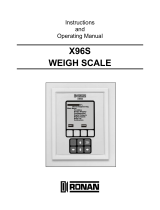 Ronan Engineering X96S Instructions And Operating Manual
-
-
KLINGER 451 Operating instructions
-
 NOSHOK 920 Series RTD Transmitter Software User manual
-
Teracom TSH230 User manual


