Page is loading ...

1660K024B Page 1 of 30
Introduction to the DC-41SRTHO
The DC-41SRTHO display is presented as an easy-to-use clock, thermometer, hygrometer and CO2
measurer adjusted and calibrated at factory. The main window shows the current hour and minute,
temperature with 0,1ºC resolution, humidity with 1% resolution and CO2 concentration with 1ppm resolution.
The main window can be set to turn on and turn off at the time set by user and is adjustable in brightness (see
“Parameters of the display” in this manual). There are add-on functions depending on the display. These
functions are fully compatible and can be combined with each other:
If the display includes option A, it has an integrated GPS. The antenna contents a magnet that permit
to fix it to a magnetic surface. The first time the display is turn on, the quality of the GPS signal must be
verified some minutes after the power-up. This is done using one of the parameters of the display (see “GPS
option”in this manual).
If the display includes option NE (Ethernet connectivity), this display hosts a web site where the user
can see the status of the display and configure it. This function allows the display to be used as a server for
other displays to synchronize the hour through the Ethernet, as well as updating its time and date through a
SNTP server. User can configure and request the time through TCP/IP commands. The default IP is
192.165.1.100. See “Ethernet option” in this manual for more information.
If the display includes option X (RS-485 connectivity), this display can be configured as a RS.485
server/client. This means that the display can connect with other displays to sync between them, as well as
the user communication through commands. If the display also includes the GPS or the Ethernet option, the
display can work as a bridge between both options. See “RS-485 option” for more information
TECHNICAL MANUAL DC-41SRTHO
Clock, thermometer, hygrometer and CO2 measurement with
GPS, RS-485 and Ethernet.

1660K024B Page 2 of 30
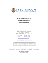
Installation of the DC-41SRTHO
4 fixation
points
The DC-41SRTHO displays can be fixed to the wall in two ways:
1– Hanged. Place 2 of the supplied plug at 314mm from one to the other. Insert the screws leaving
their head outside for 4mm. Hang the display using the upper-side zig-zag.
2– Screwed. Remove the methacrylate cover. Place the 4 supplied plugs at the distance showed in
the drawing. Place the 2 upper screws, leaving their head outside for 4 mm. Hang the display using the upper-
side zig-zag. Place the lower screws Tighten all the screws. Replace the methacrylate cover.
Powering the display
Power supply must be from 100VAC to 240VAC, 50/60 Hz . You must use a Schuko type plug that
has grounded terminal.
In case you have to lengthen the cord, the connection must be made on the terminal located within
the display.

1660K024B Page 3 of 30
DC-41SRTHO characteristics.
Power supply ............................................... 100 VAC a 240 VAC 50/60Hz
Consumption ................................................ 35VA
Consumption at minimum brightness ....... 13,2VA.
Display
Time ............................................................... 4 digits 7segments 100mm height. Format HH:MM. Red LED.
Temperature .................................................. 3 digits 7segments 100mm height. Red LED.
Humidity ......................................................... 2 digits 7segments 100mm height. Red LED.
CO2 measure ................................................. 4 digits 7segments 57mm height. Red LED.
....................................................................... Visibility 50 meters. (25mm in CO2)
Environmental conditions .......................... Operating temperature: -20 to 60ºC.
....................................................................... Storage temperature: -30ºC to 70ºC
....................................................................... Relative humidity: 5-95% non condensation.
....................................................................... Maximum environmental lighting: 1000 lux.
....................................................................... Protection IP 41.
Weight ........................................................... .4,5 Kg.
Temperature precision ................................ ±0,5ºC at 25ºC
Temperature resolution .............................. 0,1ºC
Humidity precision ...................................... ±3,5% between 30% and 70%
Humidity resolution ..................................... 1%
Precisión CO2 ............................................... ±30ppm or 3% of the measurement between 400 and 1250ppm
Resolución CO2 ............................................ 1ppm
Timed power-up of the display
This display operates in two operation modes: full-operative mode and power-saving mode. In power-
saving mode the display does not show the time in order to save energy when the display is not needed. If the
power-saving function is not needed and the display should always powered up, the both power-up and
power-down times must be the same.
Parameters of the display
There are three keys on the back side of the display. These keys are used to access and navigate
through the menu of the display. The identification of the keys is
Advance key. Access parameter/switch digits
Enter key. Validate parameter.
Increase key. Increase the value of the selected digit
Error displaying
The only error that can appear is a temperature/humidity error. The text displayed in this case is E02 in the
display. If this occurs, reboot the display.

1660K024B Page 4 of 30
Changing the time
In case the user wants to change the time, the Advance key must be pressed for three seconds.
Using the Advance (to change digit) and the Increase (to increase the value of the digit) keys the present time
can be changed. To leave the menu, press the Advance key past the digit corresponding to the units of the
minute. If the time has changed, the seconds are changed to 0 when leaving the menu. Take in consideration
that the time displayed in the menu must be UTC time. In case the display is configured to sync using the
GPS or the SNTP connection, the time inserted by the user will be overwritten.
Modify parameters
If the user presses the Advance key for 6 seconds the parameter menu is displayed. In all cases the
number the user is modifying is the one that flashes. The complete diagram of the parameters can be found in
annex 1. In order to make configuration easy for the user, when changing a parameter, a point is turned on.
This point changes depending on the sub-parameter (if it exists) the user is in.
8.8:88
88:88
8.8:88
88:8.8
ENTER
ENTER
ENTER
Parameters are detailed below:
Parameter 1: Date configuration: This parameter configures de date, as well as the wintertime/summertime
automatic switchover configuration. When entering this parameter, the day can be changed using the
Increase and Advance key. To switch to month configuration, press the Enter key. Navigation here is the
same as before. Once set the month, press the Enter key to switch to year configuration. Navigation here is
the same as before. Once set the year, press the Enter key to switch to the following parameter, which has
two parts:
Left digit: wintertime/summertime automatic switchover configuration
0 - Automatic switchover disabled. Time offset must be changed increasing or reducing value
in parameter 3, leaving as the internal time, the UTC time.
1 - Automatic switchover enabled.
Right Digit: Weekday.
It allows to configure the present weekday, where 1 is Monday and 7 is Sunday

1660K024B Page 5 of 30
Parameter 3: Time offset: This parameter allows the user to configure its time zone, as well as changing the
time offset in summertime/wintertime when configuring it manually, or for personal purposes; always counting
that internal time count of the clock is GMT. First digit shows an upper hyphen when adding time and a
hyphen when subtracting
Parameter 4: Display configuration: This parameter configures other functionalities of the display, as the
brightness and the sync options.
Brightness configuration consists of two parts:
Left digit. Manual or automatic control of brightness
0 - Automatic control of brightness depending on the room light.
1 - Manual control of brightness. Fixed brightness depending on the right digit.
Right digit. Brightness level.
The functionality of this digit depends on the left digit:
Automatic mode – Selection of the minimum brightness of the display when the room is in
darkness. Minimum brightness is 1 and maximum is 5. With light, the display adapts to the amount of
light in the room.
Manual mode - Selection of the brightness level. 1 is minimum and 5 is maximum brightness
The second parameter (Accessed through the Enter key once selected the brightness configuration)
configures the time sync depending on the capabilities and the user desires. If the user selects a sync not
allowed by capabilities, the display will not sync. For example, a display without Ethernet connection, selecting
SNTP sync will have no effect. Options are:
0. Do not sync.
1. Sync with another display through Ethernet.
2. Sync through SNTP.
3. Sync with another display through RS-485.
4. Sync through GPS.
Parameter 5: Display power-up time: This parameter configures the time the display changes form power-
.save mode to full-operative mode. When accessing in this parameter, the hour the display changes to full-
operative mode is shown. When the Enter key is pressed, the minutes are shown. To go back to the
parameter menu, press the Enter key again.
Parameter 6: Display power-down time: This parameter configures the time the display changes from full-
operative mode to power-save mode. When accessing in this parameter, the hour the display changes to
power-save mode is shown. When the Enter key is pressed, the minutes are shown. To go back to the
parameter menu, press the Enter key again.
Parameter 7: Website language. This parameter is shown if the display includes Ethernet option.
0 - Catalan
1 - Spanish
2 - English
3 – French
4 - German
Parameter 8: Display IP. This parameter is shown if the display includes Ethernet option. This
parameter allows the user to change the IP address of the display. Access this parameter pressing the
Advance key. Once inside, the first number of the IP address is shown. Modify it using the Increase and
Advance keys and validate it using the Enter key. Do the same with the other 3 numbers of the IP address. To
identify each number, think that the first number is shown without decimal point. Next numbers appear with
decimal points, shifting left each number.

1660K024B Page 6 of 30
Parameter 9: RS-485 configuration. This parameter is shown if the display includes RS-485 option:
Access this parameter pressing the Advance key. Change the code according to the desired configuration.
Code
Baud Rate
Data bits
Parity
Stop bits
01
4800 Bauds
7 bits
No parity
1
02
9600 Bauds
7 bits
No parity
1
03
19200 Bauds
7 bits
No parity
1
04
4800 Bauds
8 bits
No parity
1
05
9600 Bauds
8 bits
No parity
1
06
19200 Bauds
8 bits
No parity
1
07
4800 Bauds
7 bits
Even
1
08
9600 Bauds
7 bits
Even
1
09
19200 Bauds
7 bits
Even
1
10
4800 Bauds
8 bits
Even
1
11
9600 Bauds
8 bits
Even
1
12
19200 Bauds
8 bits
Even
1
13
4800 Bauds
7 bits
Odd
1
14
9600 Bauds
7 bits
Odd
1
15
19200 Bauds
7 bits
Odd
1
16
4800 Bauds
8 bits
Odd
1
17
9600 Bauds
8 bits
Odd
1
18
19200 Bauds
8 bits
Odd
1
19
4800 Bauds
7 bits
No parity
2
20
9600 Bauds
7 bits
No parity
2
21
19200 Bauds
7 bits
No parity
2
22
4800 Bauds
8 bits
No parity
2
23
9600 Bauds
8 bits
No parity
2
24
19200 Bauds
8 bits
No parity
2
25
4800 Bauds
7 bits
Even
2
26
9600 Bauds
7 bits
Even
2
27
19200 Bauds
7 bits
Even
2
28
4800 Bauds
8 bits
Even
2
29
9600 Bauds
8 bits
Even
2
30
19200 Bauds
8 bits
Even
2
31
4800 Bauds
7 bits
Odd
2
32
9600 Bauds
7 bits
Odd
2
33
19200 Bauds
7 bits
Odd
2
34
4800 Bauds
8 bits
Odd
2
35
9600 Bauds
8 bits
Odd
2
36
19200 Bauds
8 bits
Odd
2
Once the serial line is configured, press the Enter key to modify the display address. This must be between 01
and 99. If the user presses the Enter key again, the End of Block can be modified. This can be:
Code
End of block
0
0Dh
1
0Ah
2
0Dh 0Ah
3
0Ah 0Dh
4
2Ah 0Dh
5
02h
6
03h
7
04h
Press the Enter key to go back to the menu.

1660K024B Page 7 of 30
Parameter A: GPS signal level: This parameter is only seen if the display includes GPS function. This
parameter shows the quality of the GPS signal arriving to the antenna. Its maximum value is 50 and it must be
over 20. If this occurs, the antenna must be moved closer to a window to get more signals.
Parameter J: Maintenance parameter: This parameter is used in factory and must not be modified.
Parameter P: Exit menu: Press Advance key to leave menu.
GPS option
Displays that include GPS sync with the GPS standard signal. This allows a better time sync without
Ethernet connectivity
GPS antenna includes a magnet that can be fixed to a ferric surface. This antenna must be placed
close to a window or in a place with “thin” roof. The most “hidden” the antenna is, the longer will take to get
the GPS signal. GPS can spend up to half an hour to fix the signal if the antenna is “hidden” from the outside.
If, after half an hour, the A parameter is lower than 20, move the antenna abroad.
The important parameters user must take in account are:
Parameter 4.2: To sync through GPS, this parameter must be 4.
Parameter A: This parameter shows the GPS signal quality.

1660K024B Page 8 of 30
Ethernet option
Ethernet options allows a new step in this displays type because it allows to connect displays using
the same LAN in the installation, syncing them through the SNTP and providing a new user interface through
the Web.
The first connection
There are several ways for accessing the display on the first time it’s connected to the network.
One of the ways is changing the IP address through parameters seen before
If the IP 192.168.1.100 (the default IP of the display) is in the range of your LAN, the display can be accessed
typing the IP in the URL bar in your favourite browser.
In case there is more than one display in the LAN or the default IP of the display is out of the IP range of you
LAN, it is recommended to use the PC program “Display Discoverer”, downloadable from the web. In this
program, the displays connected to the LAN are displayed, as well as their IP addresses, their MAC
addresses (all MAC are 00:04:A3:xx:xx:xx) and its name. The default name of the display is its serial number.
This name can be changed in the Ethernet tab of the web server of the display.
The first row shows the IP of the PC which is searching the displays and the second row a display we just
have bought. As it is shown, the display has serial number 16601234 and the default IP is out of the range of
the LAN. To change the IP address to a suitable one for our LAN, select the display and click the button
“Change IP”. When clicking this, a new window is opened where a new IP address can be tipped.

1660K024B Page 9 of 30
Tip the new IP and click OK. There will appear a message in the main window with the message sent to the
display.

1660K024B Page 10 of 30
After some seconds, click the “Refresh” button. The display appears with the new IP
Click the display IP to open a new tab in the browser. The main page of the web server is shown.

1660K024B Page 11 of 30
User interface
Ethernet connection allows a new interface, much easier than the usual in displays. All configuration
can be done through a website hosted at the display, so the user only needs a device connected to the LAN
with web browser (computers, smartphones, tablets…). There is no contact with the display, which usually is
in a difficult access point. The web page can be accessed remotely if the router is correctly redirected. See
Annex 2: View the web page remotely for more information.
The main page shows the same date and time of the display, as well as the GPS signal quality (if the
option is included) and the display IP. This main page is for the user to control the status of the display.
In the left menu there are two tabs: Configuration and Ethernet, accessible through user and
password:
User: admin
Password: 12345678

1660K024B Page 12 of 30
First tab allows the user to configure the same parameters as the parameter menu in an easier and
more intuitive way. When the user configures the display to sync through SNTP or another display, the server
must be written in the field.
The second tab allows configuring the network parameters of the display, including the IP address,
DNS, etc. The display can use DHCP to get these parameters on its own. The name of the display can be
changed according to the needs of the user. This name is used to identify and access the display throw web
browser (typing the name in the URL)
In case of failure or errors, reset the display by pressing the three keys all during a reset.

1660K024B Page 13 of 30
Ethernet network
Many Ethernet networks can be configured to sync one or more displays. The possible networks are shown
below, as well as the main actions/parameters (seen from the webpage) the user must configure. Other
parameters don’t care.
Networks with one display
One display
Ethernet network
Ethernet network
Time and date
introduction by user,
if necessary
Configure net parameters
Sync: no
One display with GPS
Ethernet network
Ethernet network
Review parameter A: GPS signal
Sync: GPS
Review
parameter A
from the web

1660K024B Page 14 of 30
One display. SNTP sync
There are two options. Both are configured the same way.
Ethernet network
Ethernet network
Ethernet network
Ethernet network
SNTP server
Configure net parameters
Sync: SNTP
Write the server addres in the
field.
SNTP server
Configure net parameters
Sync: SNTP
Write the server addres in the
field.

1660K024B Page 15 of 30
Nets with more than one display
Sync through a display with GPS
The server display syncs itself with the GPS and others sync with the server display.
Ethernet network
Ethernet network
Client display
Configure net parameters
Sync: Display Ethernet
Write the display server addres
in the field.
Server display
Configure net parameters
Sync: GPS
DHCP: no.
Client display
Configure net parameters
Sync: Display Ethernet
Write the display server addres
in the field.

1660K024B Page 16 of 30
Sync through SNTP. Only one display connects to the SNTP server.
This works for both cases: connecting to a local SNTP server o a cloud SNTP server. Only one display is
connected to the SNTP server and serves the time to the other displays
Ethernet network
Ethernet network
Client display
Configure net parameters
Sync: Display Ethernet
Write the display server addres in
the field.
Server display
Configure net parameters
Sync: SNTP
Write the server addres in the
field.
DHCP: no.
SNTP server
Client display
Configure net parameters
Sync: Display Ethernet
Write the display server addres in
the field.

1660K024B Page 17 of 30
Sync through SNTP. All displays connect to the SNTP server
This works for both cases: connecting to a local SNTP server o a cloud SNTP server. All displays update
from the SNTP server specified.
Ethernet network
Ethernet network
Configure net parameters
Sync: SNTP
Write the server addres in the
field.
SNTP server
Configure net parameters
Sync: SNTP
Write the server addres in the
field.
Configure net parameters
Sync: SNTP
Write the server addres in the
field.

1660K024B Page 18 of 30
Communication with commands through Ethernet
The displays can obtain the displayed parameters through commands, as well as force the display time
through TCP/IP commands. In this case, the display must be configured for not to sync another way or the
sync will rewrite the programmed time. The frames are sent in ASCII (character) format. The end of block is
the one defined by the user through the web page.
The following frames can be sent
Command
Code
Data
End of block
Display time request
P H
Display temperature request
P T
Display humidity request
P U
Displayed CO2 request
P C
Time programming
F H
Display time request
Frame
This frame only includes the code. This does not send any data.
Code
End of block
ACII
P H
Hexa
50h 48h
Response frame
Code
Data
End of block
Code
Day
Month
Year
Space
Hour
Minute
Second
End of block
ASCII
R H
DD
MM
AA
HH
MM
SS
Hexa
52h 48h
20h
Example: 13:06:00 16/05/2013
Code
Data
End of block
Code
Day
Month
Year
Space
Hour
Minute
Second
End of block
ASCII
R H
16
05
13
13
16
00
Hexa
52h 48h
31h 36h
30h 35h
31h 33h
20h
31h 33h
31h 36h
30h 30h

1660K024B Page 19 of 30
Display temperature request
Frame
This frame only includes the code. This does not send any data.
Code
End of block
ACII
P T
Hexa
50h 54h
Response frame
Code
Data
End of block
ASCII
R T
T
T
.
T
Hexa
52h 54h
2Eh
Example: Temperature=17.2ºC
Code
Data
End of block
ASCII
R T
1
7
.
2
Hexa
52h 54h
31h
37h
2Eh
32h
Display humidity request
Frame
This frame only includes the code. This does not send any data.
Code
End of block
ACII
P U
Hexa
50h 54h
Response frame
Code
Data
End of block
ASCII
R U
H
H
Hexa
52h 54h
Example: Humidity=60%
Code
Data
End of block
ASCII
R U
6
0
Hexa
52h 54h
36h
30h

1660K024B Page 20 of 30
Displayed CO2 concentration request
Frame
This frame only includes the code. This does not send any data.
Code
End of block
ACII
P C
Hexa
50h 43h
Response frame
Code
Data
End of block
ASCII
R C
C
C
C
C
Hexa
52h 43h
Example: CO2 concentration=728ppm
Code
Data
End of block
ASCII
R U
0
7
2
8
Hexa
52h 54h
30h
37h
32h
38h
Time programming
Frame
Code
Data
End of block
Code
Day
Month
Year
Space
Hour
Minute
Second
End of block
ASCII
F H
DD
MM
AA
HH
MM
SS
Hexa
46h 48h
20h
Example: 13:06:00 16/05/2013
Code
Data
End of block
Code
Day
Month
Year
Space
Hour
Minute
Second
End of block
ASCII
F H
16
05
13
13
16
00
Hexa
46h 48h
31h 36h
30h 35h
31h 33h
20h
31h 33h
31h 36h
30h 30h
/