Page is loading ...

1600K08J
USER MANUAL
DC-20 and DC-21
Thermometer and hygrometer


Content
1. INTRODUCTION AND GENERAL CHARACTERISTICS ......................................................................... 1-1
1.1. Characteristics of the DC-20 and DC-21 displays ............................................................................ 1-2
1.2. Temperature and humidity sensor characteristics. ........................................................................... 1-2
1.3. Weight of the displays. ...................................................................................................................... 1-3
1.4. Dimensions of the DC-20 and DC-21. .............................................................................................. 1-3
1.4.1. Dimensions of the DC-20S and DC-21S. ................................................................................. 1-3
1.4.2. Dimensions of the DC-20D and DC-21D. ................................................................................. 1-3
1.4.3. Dimensions of the sensor case................................................................................................. 1-3
1.5. Display mounting .............................................................................................................................. 1-4
1.5.1. Mounting of the DC-20S and DC-21S. ..................................................................................... 1-4
1.5.2. Mounting of the DC-20D and DC-21D. ..................................................................................... 1-5
2. INSTALLATION ......................................................................................................................................... 2-1
2.1. Accessing inside the display. ............................................................................................................ 2-1
2.2. Powering the display. ........................................................................................................................ 2-1
2.3. Serial line connection. ....................................................................................................................... 2-2
2.4. Placing the sensor. ........................................................................................................................... 2-2
3. OPERATION. ............................................................................................................................................ 3-1
3.1. Initial reset. ....................................................................................................................................... 3-1
3.1.1. Displays with several sensors................................................................................................... 3-1
3.2. Programming parameters ................................................................................................................. 3-1
3.2.1. Modify parameters RS-485, Ethernet or Wifi. ........................................................................... 3-2
3.3. RS-485 parameters. ......................................................................................................................... 3-3
3.3.1. Parameter 1 for RS-485: Address of the display. ..................................................................... 3-3
3.3.2. Parameter 2 for RS-485: Serial line configuration. ................................................................... 3-3
3.3.3. Parameter 3 for RS-485: Sensor control and communication protocol .................................... 3-4
3.3.4. Parameter F: Exit menu ............................................................................................................ 3-4
3.4. Parameters Ethernet and Wifi. ......................................................................................................... 3-5
3.4.1. Parameter 1 for Ethernet and Wifi: MAC address of the display. ............................................. 3-5
3.4.2. Parameter 2 for Wifi: Load the IP configuration through the RS-232 port. ............................... 3-5
3.4.3. Parameter 3 for Ethernet and Wifi: Sensor control and communication protocols................... 3-5
3.4.4. Parameter 4 for Ethernet and Wifi: Load the default port configuration in the Ethernet or Wifi
port. .................................................................................................................................................. 3-5
3.4.5. Parameter F: Exit menu. ........................................................................................................... 3-5
4. COMMUNCATION PROTOCOLS............................................................................................................. 4-1
4.1. ASCII protocol for RS-485 ................................................................................................................ 4-1

4.1.1. Displays DC-20/X. Read values from the display ..................................................................... 4-2
4.1.2. Displays DC-21/X. Send values to the display ......................................................................... 4-2
4.2. PROTOCOL MODBUS RTU - ASCII for RS-485 ............................................................................. 4-4
4.3. PROTOCOL MODBUS RTU - Word for RS-485 .............................................................................. 4-6
4.4. TCP/IP, UDP/IP PROTOCOL ........................................................................................................... 4-8
4.4.1. UDP protocol ............................................................................................................................ 4-8
4.4.2. Read values from the display ................................................................................................... 4-8
4.4.3. Send values to the display. Displays without sensor. ............................................................... 4-9
4.5. ModBus/TCP PROTOCOL ............................................................................................................. 4-10
4.5.1. Modbus/TCP protocol ............................................................................................................. 4-10
4.5.2. Read data from the display ..................................................................................................... 4-10
4.5.3. Send temperature and humidity ............................................................................................. 4-11
4.1. IP Address. Ethernet option ............................................................................................................ 4-13
4.2. Modifying the port settings. ............................................................................................................. 4-13
4.2.1. UDP/IP configuration .............................................................................................................. 4-14
4.3. IP address. Wifi. .............................................................................................................................. 4-15
4.3.1. Accessing Wifi module configuration ...................................................................................... 4-17
4.4. Set up IP Address using the DeviceInstaller. ................................................................................. 4-20
4.5. Modifying the port settings. ............................................................................................................. 4-20

CHAPTER 1
INTRODUCTION AND GENERAL CHARACTERISTICS
1-1
DC-20 and DC-21 operation manual
1. INTRODUCTION AND GENERAL CHARACTERISTICS
Numerical displays DC-20 and DC.21 are displays for the accomplishment of the Real
Decreto 1826/2009, in the section relative to the temperature and humidity displaying in the
public access locals with air-conditioning.
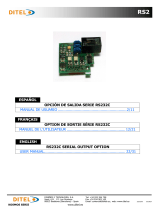
DC-20 displays admit form 1 to 5 sensors, calculating the
mean value of all them. It automatically detects the number of
sensors and displays its state once the display is initialized.
The temperature and humidity sensor is placed in a case that
permits a very easy installation using the support included in
the package. The recommended position of the sensor is at
1,7m from the floor. The display can include RS-485, Ethernet
or Wifi connectivity as options.
DC-21 displays are aesthetically identical to the DC-20 but do
not have sensor. They must receive the data from RS-485,
Ethernet or Wifi.
Hr 30-70%
Max. 21°C
Min. 26°C
°C
%
RS-485
Ethernet
WIFI
Hr 30-70%
Max. 21°C
Min. 26°C
°C
%
OPTIONS:
RS-485
Ethernet
WIFI

1-2
INTRODUCTION AND GENERAL CHARACTERISTICS
CHAPTER 1
DC-20 and DC-21 operation manual
1.1. Characteristics of the DC-20 and DC-21 displays
Supply Voltage........................................... 88 to 264 VAC 47 to 63Hz.
Consumption DC-20S and DC-21S .......... 12VA.
Consumption DC-20S and DC-21S .......... 24VA.
Display ....................................................... 7 segments, 100mm high + decimal point.
..................................................................... LED colour red, blue, white or green depending on
..................................................................... the model
..................................................................... Viewing distance: max 50 meters.
Text ............................................................. Silkscreen with maximum limits.
Environmental Conditions ........................ Operation Temperature: -20 to 60ºC.
..................................................................... Storage temperature: -30ºC to 70ºC.
..................................................................... Humidity: 5-95% RH non condensing.
..................................................................... Maximum environmental illumination: 1000 lux.
..................................................................... Sealing: IP41 .
1.2. Temperature and humidity sensor characteristics.
Temperature sensor
Resolution .......................................... 0.1°C
Precision ............................................ ±0.5° at 25°C
Response time ................................... 20s
Working range ................................... -20°C to 80°C
Humidity sensor
Resolution .......................................... 1%
Precision ............................................ ±3.5% between 30% and 70%
Response time ................................... 4 s
Environmental Conditions ..................... Sealing: IP65 .

CHAPTER 1
INTRODUCTION AND GENERAL CHARACTERISTICS
1-3
DC-20 and DC-21 operation manual
1.3. Weight of the displays.
The weight of the DC-20S and DC-21S is 5kg.
The weight of the DC-20D and DC-21D is 7kg.
1.4. Dimensions of the DC-20 and DC-21.
1.4.1. Dimensions of the DC-20S and DC-21S.
Hr 30-70%
Max. 21°C
Min. 26°C
°C
%
520
320
40
22
1.4.2. Dimensions of the DC-20D and DC-21D.
°C
%
Hr 30-70%
Max. 21°C
Min. 26°C
520
320
80
1.4.3. Dimensions of the sensor case
The dimensions of the sensor case in mm are:

1-4
INTRODUCTION AND GENERAL CHARACTERISTICS
CHAPTER 1
DC-20 and DC-21 operation manual
1.5. Display mounting
1.5.1. Mounting of the DC-20S and DC-21S.
The DC-20S and DC-21S displays can be fixed to the wall in two ways:
1– Hanged. Place 2 of the supplied plug at 410mm from one to the other. Insert the
screws leaving their head outside for 4mm. Hang the display using the upper-side zig-zag.
2– Screwed. Remove the methacrylate cover. Place the 4 supplied plugs at the distance
showed in the drawing. Place the 2 upper screws, leaving their head outside for 4 mm. Hang the
display using the upper-side zig-zag. Place the lower screws Tighten all the screws. Replace
the methacrylate cover.
The screws and plugs are provided with the display
4 Fixation Points
410
289
Hanged:
4 mm
PARED

CHAPTER 1
INTRODUCTION AND GENERAL CHARACTERISTICS
1-5
DC-20 and DC-21 operation manual
Screwed:
1.5.2. Mounting of the DC-20D and DC-21D.
The DC-20D and DC-21D displays must be hanged using the rings the display has. Cables
or chains can be used
The power cables and the sensor can be fixed to the mounting elements without tightening
them.
IN ANY WAY THE POWER OR THE SENSOR CABLES CAN BE USED FOR HANGING
THE DISPLAY
PARED


CHAPTER 2
INSTALLATION
2-1
DC-20 and DC-21 operation manual
2. INSTALLATION
The installation of the DC-20 and DC-21 is not particularly delicate but some important
considerations must be taken into account.
The display must not be anchored to places subject to vibrations, nor should it be installed
in places which generally surpass the limits specified in the display characteristics, both in terms
of temperature and humidity.
The degree of protection of displays DC-20 and DC-21 is IP41, meaning that they are
protected against penetration by solid foreign objects of a diameter of about 1mm and against
the vertical fall of water droplets. Sealing of the sensor case is IP65, what means that is
completely isolated from dust and jets of water
Displays DC-20 and DC-21 should not be installed in places with an illumination level in
excess of 1000 lux. Neither should the display be placed in direct sunlight as visibility would be
lost.
2.1. Accessing inside the display.
The access to the interior of the display is only authorised to technical staff. The interior
must be accessed only for installation and maintenance purposes only.
Disconnect the power of the display before its manipulation
To access the interior, unscrew the 4 screws placed in both sides (2 screws per side) Allen key
2mm.
2.2. Powering the display.
Power supply must be from 100VAC to 240VAC, 50/60 Hz. You must use a Schuko type
plug that has grounded terminal.
In case you have to lengthen the cord, the connection must be made on the terminal
located within the display.
In two-sided displays, DC-20D and DC-21D, the powering cable enters in the display
through a gland.

2-2
INSTALLATION
CHAPTER 2
DC-20 and DC-21 operation manual
2.3. Serial line connection.
The displays of the series DC-20X and DC-21X admit connection through the RS-485 line.
The connection must be done using a DB9 connector placed in the interior of the display
The connection schematic is the one that follows
1
2
3
4
5
6
7
8
9A
BRS-485
DB9
Plug
2.4. Placing the sensor.
The temperature and humidity sensor is placed in a black nylon part, protected by a cap
that permits the humidity to pass through but not water. The connexion cable enters through a
gland. The set must not be manipulated to keep the IP65 sealing.
Slot for mounting on support
In the displays with more than one sensor, there is no order or priority. There can be
connected between 1 and 5 sensors in any of the connectors. The display detects the sensor
when powering on the display.
The temperature and humidity sensor should be placed at 1,7m high from the floor. Due
to the fact that the display is expected to be in crowded places, it is recommended to protect the
cable of the sensor using a tube.

CHAPTER 2
INSTALLATION
2-3
DC-20 and DC-21 operation manual
In the sensor placing must be avoided:
1. The air streams due to doors
2. Placing it in climate control systems outputs
3. Proximity to fridges
4. Walls with direct sunlight
In case the sensor cable must be extended, the colours of the cables must be respected. The
colour identification is
BL = White
MAR = Brown
VER = Green
AMA = Yellow
The cable type must be YCY 4 x 0.22 shielded


CHAPTER 3
OPERATION
3-1
DC-20 and DC-21 operation manual
3. OPERATION.
3.1. Initial reset.
Before connecting the display to the network, we must ensure that all of the connections have
been carried out correctly and that the display is firmly in place.
Each time we connect the display to the power supply network, an initial reset occurs which
tests all of the segments comprising the display. The test consists of the sequential illumination
of all of the digits with the number "8", all of the digits with the value "0", all of the decimal points
are lit up and finally the version code.
From this point, the DC-20 displays show the active sensors (activated = 1, deactivated = 0)
and then the current temperature and the humidity
In the DC-21 displays, the version code is displayed until the first message with data is
received.
3.1.1. Displays with several sensors.
In the displays with several sensors, the displayed value is the mean value of the sensed by
the connected sensors,
The display detects the connected sensors and calculates the mean value depending on
the active sensors.
If when powering up there is no sensor detected, “0” is displayed in the 5 digits. If once the
display is initialized there is no sensor detected, “E02” is displayed instead of the temperature
3.2. Programming parameters
Displays with connectivity options or analog inputs must be programmed previously to its
use. The parameters the user must configure are:
Displays with RS-485 serial line
1- Address of the display in the network.
2- Transmission baud rate, data bits, parity, stop bits.
3- Sensor control and communication control: ASCII, Modbus RTU-ASCII, Modbus
RTU-Word
F- Quit menu. Press “*”
Displays with Ethernet and Wifi
1- Display the MAC address of the display
2- No use.
3- Sensor control and communication protocol: TCP/IP and Modbus/TCP
4- Reset communications port.
F- Quit menu. Press “*”

3-2
OPERATION
CHAPTER 3
DC-20 and DC-21 operation manual
3.2.1. Modify parameters RS-485, Ethernet or Wifi.
To modify the parameters the user must access the three programming keys placed on the top
inside the display. See paragraph 3.1 to see how to access inside the display.
The programmation keys are placed in the top of the displays. The identification of the keys is
Advance key: “* “
Increase key: “+”
To program the parameters, the three digits on the top are used. The left digit, identificated with
the digital point, indicates the parameter number and the two right digits indicate its value. The
flashing digit is the one the user can modify with the “+” key
To enter the menu, main the “*” key pressed for 3 seconds. Once this time is passed, the first
parameter is displayed.
There are then two options:
1- Modify the parameter value
By pressing the Advance key "*", entry is gained to modify the parameter value.
To go back to displaying the parameter number, press “*”again.
To increase the parameter value, press the “+” key.
2- Select another parameter
In order to select another parameter, the parameter number must be made to flash using the “*”
key and then the new parameter may be selected using the “+” key.

CHAPTER 3
OPERATION
3-3
DC-20 and DC-21 operation manual
3.3. RS-485 parameters.
3.3.1. Parameter 1 for RS-485: Address of the display.
It allows to configurate the address of the display in the RS-485 network. Value between
0 and 99.
3.3.2. Parameter 2 for RS-485: Serial line configuration.
The parameters of the serial line are codified in the following table:
Code
Baud Rate
Data bits
Parity
Stop bits
01
4800 Bauds
7 bits
No parity
1
02
9600 Bauds
7 bits
No parity
1
03
19200 Bauds
7 bits
No parity
1
04
4800 Bauds
8 bits
No parity
1
05
9600 Bauds
8 bits
No parity
1
06
19200 Bauds
8 bits
No parity
1
07
4800 Bauds
7 bits
Even
1
08
9600 Bauds
7 bits
Even
1
09
19200 Bauds
7 bits
Even
1
10
4800 Bauds
8 bits
Even
1
11
9600 Bauds
8 bits
Even
1
12
19200 Bauds
8 bits
Even
1
13
4800 Bauds
7 bits
Odd
1
14
9600 Bauds
7 bits
Odd
1
15
19200 Bauds
7 bits
Odd
1
16
4800 Bauds
8 bits
Odd
1
17
9600 Bauds
8 bits
Odd
1
18
19200 Bauds
8 bits
Odd
1
19
4800 Bauds
7 bits
No parity
2
20
9600 Bauds
7 bits
No parity
2
21
19200 Bauds
7 bits
No parity
2
22
4800 Bauds
8 bits
No parity
2
23
9600 Bauds
8 bits
No parity
2
24
19200 Bauds
8 bits
No parity
2
25
4800 Bauds
7 bits
Even
2
26
9600 Bauds
7 bits
Even
2
27
19200 Bauds
7 bits
Even
2
28
4800 Bauds
8 bits
Even
2
29
9600 Bauds
8 bits
Even
2
30
19200 Bauds
8 bits
Even
2
31
4800 Bauds
7 bits
Odd
2
32
9600 Bauds
7 bits
Odd
2
33
19200 Bauds
7 bits
Odd
2
34
4800 Bauds
8 bits
Odd
2
35
9600 Bauds
8 bits
Odd
2
36
19200 Bauds
8 bits
Odd
2
Table 1: RS-485 codes for configuration

3-4
OPERATION
CHAPTER 3
DC-20 and DC-21 operation manual
3.3.3. Parameter 3 for RS-485: Sensor control and communication protocol
This parameter performs two functions
Left digit: Sensor control
0-> Disable sensor information
1 -> Enable sensor information
Right digit: Communication protocol,
The user can select between the following protocols:
0: ASCII: Really simple protocol that uses ASCII characters
1: ModBus RTU-ASCII: This uses the ModBus protocol, but the temperature
and humidity data are coded in ASCII in the same block.
2: ModBus RTU-Word. This uses the ModBus RTU-Word protocol. The
temperature and the humidity are independent words.
In the display that receives the data through serial line (DC-21), the sensor information must be
disabled.
3.3.4. Parameter F: Exit menu
Press the key “*” to exit the parameter menu. Before exiting the parameters are saved.

CHAPTER 3
OPERATION
3-5
DC-20 and DC-21 operation manual
3.4. Parameters Ethernet and Wifi.
3.4.1. Parameter 1 for Ethernet and Wifi: MAC address of the display.
To know the MAC address, access parameter 1 and, using the “*” key, access the 3 last values
of the MAC address. The first 3 numbers are always 00 -20 - 4A, so the first value displayed in
the parameter is the 4th value of the MAC.
3.4.2. Parameter 2 for Wifi: Load the IP configuration through the RS-232 port.
To access the serial port for the first time, the RS-232 serial port and the Hyperterminal
(or a similar program) must be used. See paragraph 4.7.1 for more information.
3.4.3. Parameter 3 for Ethernet and Wifi: Sensor control and communication
protocols.
This parameter performs two functions
Left digit: Sensor control
0-> Disable sensor information
1 -> Enable sensor information
Right digit: Communication protocol,
The user can select between the following protocols:
0: TCP/IP: Really simple protocol that uses ASCII characters
1: ModBus TCP: This uses the ModBus protocol, the temperature and humidity
data are coded in ASCII or integer in the same block.
In the display that receives the data through serial line (DC-21), the sensor information must be
disabled.
3.4.4. Parameter 4 for Ethernet and Wifi: Load the default port configuration in the
Ethernet or Wifi port.
To load the default values in the communication port, program the value 99 and press the “*”
key. During the load time, the digits “99” are flashing. When it has finished, the parameter 4 is
displayed again.
3.4.5. Parameter F: Exit menu.
Press the key “*” to exit the parameter menu. Before exiting the parameters are saved.

/