RITE-HITE Rave RHC 1234567-001 Installation and Owner's Manual
- Type
- Installation and Owner's Manual

PRINTED IN U.S.A. PUBLICATION NO. 54450034
RITE-HITE PRINT SHOP REV. 4 © DECEMBER 2014
THIS MANUAL COVERS ALL UNITS SHIPPED DECEMBER 2014 TO DATE
INSTALLATION AND OWNER’S MANUAL

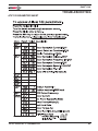
TABLE OF CONTENTS
RAVE®FAN
2Pub. No. 54450034 Rev. 4 - © DECEMBER 2014
DECLARATION OF CONFORMITY . . . . . . . . . . . . . . . . . . . . . . . . . . . . . . . . . . . . . . . . . . . . . . . . . . . .3
SAFETY . . . . . . . . . . . . . . . . . . . . . . . . . . . . . . . . . . . . . . . . . . . . . . . . . . . . . . . . . . . . . . . . . . . . . . . . . .5
GENERAL INFORMATION . . . . . . . . . . . . . . . . . . . . . . . . . . . . . . . . . . . . . . . . . . . . . . . . . . . . . . . . . . .6
SPECIFICATIONS . . . . . . . . . . . . . . . . . . . . . . . . . . . . . . . . . . . . . . . . . . . . . . . . . . . . . . . . . . . . . . . . . .8
COMPONENTS AND TOOLS . . . . . . . . . . . . . . . . . . . . . . . . . . . . . . . . . . . . . . . . . . . . . . . . . . . . . . . . .9
FAN DIMENSIONS . . . . . . . . . . . . . . . . . . . . . . . . . . . . . . . . . . . . . . . . . . . . . . . . . . . . . . . . . . . . . . . .10
MOUNTING OF THE FAN . . . . . . . . . . . . . . . . . . . . . . . . . . . . . . . . . . . . . . . . . . . . . . . . . . . . . . . . . . .11
I-BEAM AND TRUSS MOUNTING . . . . . . . . . . . . . . . . . . . . . . . . . . . . . . . . . . . . . . . . . . . . . . . . . . . .12
MOTOR BRACKET . . . . . . . . . . . . . . . . . . . . . . . . . . . . . . . . . . . . . . . . . . . . . . . . . . . . . . . . . . . . . . . .15
INSTALLATION . . . . . . . . . . . . . . . . . . . . . . . . . . . . . . . . . . . . . . . . . . . . . . . . . . . . . . . . . . . . . . . . . . .17
SPEED CONTROL STATION . . . . . . . . . . . . . . . . . . . . . . . . . . . . . . . . . . . . . . . . . . . . . . . . . . . . . . . .20
MOTOR WIRING . . . . . . . . . . . . . . . . . . . . . . . . . . . . . . . . . . . . . . . . . . . . . . . . . . . . . . . . . . . . . . . . . .21
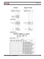
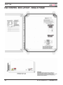
FAN CONTROLS LAYOUT . . . . . . . . . . . . . . . . . . . . . . . . . . . . . . . . . . . . . . . . . . . . . . . . . . . . . . . . . .22
FAN CONTROLS LAYOUT EMC OPTION . . . . . . . . . . . . . . . . . . . . . . . . . . . . . . . . . . . . . . . . . . . . . .24
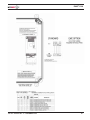
FAN CONTROLS LAYOUT SINGLE PHASE . . . . . . . . . . . . . . . . . . . . . . . . . . . . . . . . . . . . . . . . . . . .26
EMC COMPLIANCE OPTION . . . . . . . . . . . . . . . . . . . . . . . . . . . . . . . . . . . . . . . . . . . . . . . . . . . . . . . .28
CONTROL BOX WIRING . . . . . . . . . . . . . . . . . . . . . . . . . . . . . . . . . . . . . . . . . . . . . . . . . . . . . . . . . . .29
CONTROL BOX MOUNTING . . . . . . . . . . . . . . . . . . . . . . . . . . . . . . . . . . . . . . . . . . . . . . . . . . . . . . . .31
STOP CIRCUIT FOR MULTIPLE FANS . . . . . . . . . . . . . . . . . . . . . . . . . . . . . . . . . . . . . . . . . . . . . . . .32
WIND SWITCH . . . . . . . . . . . . . . . . . . . . . . . . . . . . . . . . . . . . . . . . . . . . . . . . . . . . . . . . . . . . . . . . . . .33
MOTOR WIRING CONT. / ANNUAL PLANNED MAINTENANCE . . . . . . . . . . . . . . . . . . . . . . . . . . . .34
FAN NOISE . . . . . . . . . . . . . . . . . . . . . . . . . . . . . . . . . . . . . . . . . . . . . . . . . . . . . . . . . . . . . . . . . . . . . .35
TROUBLESHOOTING . . . . . . . . . . . . . . . . . . . . . . . . . . . . . . . . . . . . . . . . . . . . . . . . . . . . . . . . . . . . . .36
PARTS . . . . . . . . . . . . . . . . . . . . . . . . . . . . . . . . . . . . . . . . . . . . . . . . . . . . . . . . . . . . . . . . . . . . . . . . . .47
CONTROLS . . . . . . . . . . . . . . . . . . . . . . . . . . . . . . . . . . . . . . . . . . . . . . . . . . . . . . . . . . . . . . . . . . . . . .52
APPENDIX-CANADIAN MARKINGS . . . . . . . . . . . . . . . . . . . . . . . . . . . . . . . . . . . . . . . . . . . . . . . . . . .54
PRODUCT INTRODUCTION
Thank you for purchasing the Rave®Fan from RITE-HITE®.
IMPORTANT READ AND SAVE THESE INSTRUCTIONS
Read and understand contents of this manual prior to installation or operation of this equipment.
For best results, have this product serviced by your authorized RITE-HITE®Representative.
NOTICE TO USER
Your local RITE-HITE®Representative provides the Planned Maintenance Program (P.M.P.) which can be fitted to your
specific operation. Call your local representative or RITE-HITE®at 1-414-355-2600 or toll free at 1-800-456-0600.
In Europe, call +31-(0)571-277505
ORIGINAL INSTRUCTIONS (ENGLISH)
The English version of this manual shall prevail over any error in, or conflicting interpretation of, any translations.
The RITE-HITE
®
products in this manual may be covered by one or more of the following U.S. patents: 4,560,315 (RE:
32,968); 4,634,334; 4,692,755; 4,744,121; 4,819,770; 4,843,373; 4,865,507; 4,920,598; 4,995,130; 5,040,258;
5,440,772; 5,442,825; 5,453,735;
37,570); 5,882,167; 5,964,572;
6,116,839; 6,190,109;
6,488,464; 6,497,067;
HITE
®
, LEVEL-RITE
®
, THINMAN
TM
, SAFE-T-LIP
®
, HYDRACHEK
®
, WHEEL-LOK
TM
, DOK-
®
, DUAL-DOK
®
,SAFE-T-STRUT and SAFE-T-GATE
®
are trademarks of
®
.
TM
,DOK-COMMANDER , JUMBO
TM
®
5,111,546; 5,212,846; 5,271,183; 5,299,386; 5,311,628; 5,323,503; 5,375,965;
5,531,557; 5,546,623; 5,553,987; 5,582,498; 5,664,930; 5,702,223; 5,762,459 (RE:
6,010,297; 6,052,268; 6,065,172; 6,070,283; 6,074,157; 6,085,375; 6,092,970; 6,106,212;
6,220,809; 6,627,016; 6,238,163; 6,322,310; 6,311,352; 6,360,394; 6,368,043, 6,431,819;
6,499,169; 6,505,713; 6,524,053; 6,634,049; 6,654,976; 6,676,360; and pending U.S. and foreign patent
applications. RITE-
LOK
RITE-HITE

RAVE®FAN
Pub. No. 54450034 Rev. 4 - © DECEMBER 2014 3

RAVE®FAN
4Pub. No. 54450034 Rev. 4 - © DECEMBER 2014
NOTES

RAVE®FAN
Pub. No. 54450034 Rev. 4 - © DECEMBER 2014 5
SAFETY
WARNING
!
When working with electrical or
electronic controls, make sure
that the power source has been
locked out and tagged according
to OSHA regulations or your
country’s local standards and
approved local electrical codes.
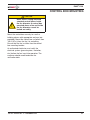
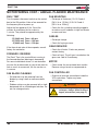
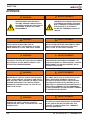
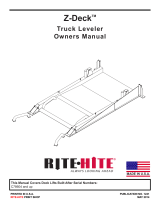
LOCKOUT / TAGOUT PROCEDURES
The Occupational Safety and Health Administration (OSHA) requires that, in addition to posting safety
warnings and barricading the work area, the power supply has been locked in the OFF position or
disconnected. It is mandatory that an approved lockout device is utilized. An example of a lockout device is
illustrated in Figure 1. The proper lockout procedure requires that the person responsible for the repairs is
the only person who has the ability to remove the lockout device.
In addition to the lockout device, it is also a requirement to tag the power control in a manner that will
clearly note that repairs are under way and state who is responsible for the lockout condition. Tagout
devices have to be constructed and printed so that exposure to weather conditions or wet and damp
locations will not cause the tag to deteriorate or become unreadable.
RITE-HITE®Corporation does not recommend any particular lockout device, but recommends the utilization
of a device that meets OSHA standards (refer to OSHA regulation 1910.147). RITE-HITE®Corporation also
recommends the review and implementation of an entire safety program for the Control of Hazardous
Energy (Lockout/Tagout). These regulations are available through OSHA publication 3120.
Figure 1
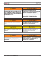
DANGER
!
Indicates a hazardous situation which, if
not avoided, will result in death or
serious injury.
WARNING
!
Indicates a hazardous situation which, if
not avoided, could result in death or
serious injury.
CAUTION
!
Indicates a hazardous situation which, if
not avoided, could result in minor or
moderate injury.
NOTICE
Indicates a situation which can cause
damage to the equipment, personal property
and/or the environment, or cause the
equipment to operate improperly.
WARNING
!
Installation to be completed in accor dance
with the National Electric Code, ANSI/NFPA
70-1999, and local codes.

RAVE®FAN
6Pub. No. 54450034 Rev. 4 - © DECEMBER 2014
GENERAL INFORMATION
DESCRIPTION
The Rave®Fan is a high-volume/low-speed (HV/LS) industrial fan that provides more
consistent air circulation and ventilation with better energy efficiency than traditional high-speed
ceiling fans or industrial floor fans.
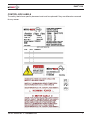
SERIAL LABEL
Model: Rave Fan
Produced: 2014
Serial Number: RHC 1234567-001
Electrical Data: 208-240V, 1ph, 50/60Hz
Diameter: 12' (3660 mm)
Rite-Hite Corporation
8900 North Arbon Drive
Milwaukee, WI 53223
USA
Tel: 1-414-355-2600
Fax: 1-414-355-9248
Made in the U.S.A.
Protected by patents 7726945 and 8142156.
Other patents pending.

RAVE®FAN
Pub. No. 54450034 Rev. 4 - © DECEMBER 2014 7
CONTROL BOX LABELS
The safety labels have specific placement and must be replaced if they are defaced or removed
for any reason.

RAVE®FAN
8Pub. No. 54450034 Rev. 4 - © DECEMBER 2014
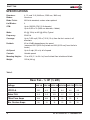
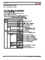
SPECIFICATIONS
Diameters: 8, 10, and 12 ft (2440 mm, 3050 mm, 3660 mm)
Blades: Aluminum
Blade Finish: Mill-finish standard, custom colors optional
# of Blades: 4
CFM: Up to 100,000 CFM (12 ft diameter)
Up to 2,830 m3/h (3660 mm diameter, 4 blade)
Watts: 60 (@ 10Hz) to 640 (@ 60Hz) Typical
Frequency: 50/60 Hz
Coverage: Up to 7,800 sq ft (725 m2) 50 ft (15 m) from the fan’s center in all
directions
Decibels: 40 to 63 dBA depending on fan speed
(measured 20 ft [6100 mm] below and 20 ft [6100 mm] from the fan’s
center)
Air Speed: Up to 5 mph (2.2 m/s) at full speed
Controls: Variable speed
Mounting Heights: 10 to 80 ft (3.1 to 24.4 m) from finished floor to bottom of blade
Weight: 150 lb (68 kg)
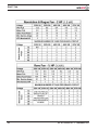
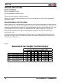
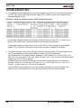
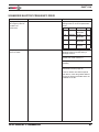
Table 2
Rave Fan - ¾ HP (½ kW)
Voltage 120V 1Φ 230V 3Φ 230V 3Φ 400V 3Φ 480V 3Φ 575V 3Φ
VFD FLA 15.7 8.5 9.6 6.4 4.8 4.2
Motor FLA 2.9 2.9 2.9 1.7 1.7 1.5
CBox Fuse Amps N/A N/A 15 10 10 6
Min. Service Amps 20 15 15 10 10 10

RAVE®FAN
Pub. No. 54450034 Rev. 4 - © DECEMBER 2014 9
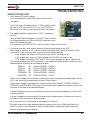
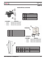
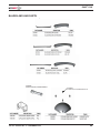
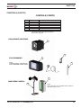
COMPONENTS AND TOOLS
UNPACKING THE COMPONENTS
You should have received the following items:
(2) boxes of fan blades, they are packed (2) per box for a total of (4) blades
– approximately 25 lb. (11.4 kg) per box.
(1) motor / hub assembly – approximately 80 lb. (36.4 kg)
(1) box containing miscellaneous mounting hardware and cables - approximately 25 lb. (11.4 kg)
(1) box containing the control box – approximately 35 lb. (15.9 kg)
Insure you have received all of the above items before installation begins. notify the factory if parts
are missing or damaged.
NOTICE
Always be environmentally responsible and
follow appropriate regulations for proper
disposal of packaging material.
TOOLS REQUIRED
(2) 7⁄16" wrenches
(2) ½" wrenches
(1) 1 ¼" box end wrench
(1) 1 1⁄16" box end wrench
(2) ¾" wrenches
(1) vice grip
(1) large standard screwdriver
(1) small standard screwdriver
(1) Torque wrench capable of 50 ft-lb
(1) Metric 7mm deep well socket - only required for motor voltage change
(1) ¼" cable cutter
(4) 10 aWG electrical terminals for motor terminations
(1) Torpedo level
If you are mounting to support angles that span building joists, you will also need a drill and a
1/2 in. drill bit.

RAVE®FAN
10 Pub. No. 54450034 Rev. 4 - © DECEMBER 2014
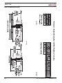
FAN DIMENSIONS
Figure 2
Table 2 Table 3

RAVE®FAN
Pub. No. 54450034 Rev. 4 - © DECEMBER 2014 11
FAN DISTANCE FROM CEILING AND
OBSTRUCTIONS
Table 4
FAN
DIAMETER
ft (mm)
MINIMUM CLEARANCE
DIMENSION AT FULL RPM
ft (mm)
8 (2440) 2 (610)
10 (3050) 3 (915)
12 (3660) 3 (915)
NOTICE
The standard blade design on the Rite-Hite
Rave™ Fan is angled upward to provide
improved airflow. A combination of
centrifugal force and air pressure causes the
blades to move upward to their operating
position. Measure the distance to possible
obstructions and mount the fan accordingly
using Table 2-3 to ensure the blades will
have proper clearance in all areas when the
fan is running. Whenever possible allow 12
in. (305 mm) additional clearance to existing
obstructions.
NOTICE
The weight of the fan that will be suspended
from the ceiling is approximately 150 lb
(68.2 kg) and will generate torque of up to
150 ft-lb (204 Nm).
If the ceiling support structure is an openweb
design, all hanging dimensions can be
taken from the underside of the ceiling. If the
ceiling’s support structure is a solid beam or
solid channel, all measurements must be
taken from the bottom of the beam as the
basis point for the hanger dimension. If the
roof is pitched, this must be accounted for
above the tips of the blades. Failure to follow
these guidelines will result in limited air
movement from the fan.
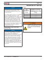
MOUNTING OF THE FAN
WARNING
!
To reduce the risk of fire, electric
shock, or personal injury, mount
directly to a structural framing
member.

RAVE®FAN
12 Pub. No. 54450034 Rev. 4 - © DECEMBER 2014
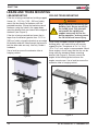
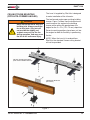
I-BEAM AND TRUSS MOUNTING
I-BEAM MOUNTING
If the fan is being mounted to a building support
I-beam (6 – 13-1/2 in. [150 – 350 mm] wide),
mount the fan directly to the beam with the
provided brackets. Clamp the brackets around
the beam using the holes in the upper beam
mounting bracket that are closest to the edge of
the beam (see Figure 5).
If the fan is being mounted to a beam that is
larger than the bracket (greater than 13-1/2 in.
[350 mm] wide), clamp the bracket on one edge
of the beam and drill holes through the beam to
bolt the other side securely. Use only Grade 8
hardware.
Use a level to ensure the extension tube is
hanging vertical.
Figure 5
CEILING TRUSS MOUNTING
When using a support channel to span two
building joists, use material that will securely
support the fan. Two pieces of 3 x 3 x 1/4 in.
(75 x 75 x 7 mm) angle is recommended. Mount
these angles in such a way that the fan can be
hung using the standard I-beam mounting
bracket (see Figure 6). Securely mount the
angles to the building joists to ensure the
angles cannot move. Use a level to ensure the
extension tube is hanging vertical.
Figure 6
WARNING
!
!
Never mount the fan to only one
building joist. Always mount the
fan to two joists. One joist will
not provide the rigidity and
support necessary for the fan
during operation, and may cause
the fan to fall and cause injury.

RAVE®FAN
Pub. No. 54450034 Rev. 4 - © DECEMBER 2014 13
CEILING TRUSS MOUNTING
(RITE-HITE–FORMED ANGLES)
The truss kit supplied by Rite-Hite is designed
to make installation of the kit easier.
The two formed angles span existing building
trusses. Figure 7 shows how the brackets are
used to secure the angles to the building
trusses while setting the gap between the
angles for the 3 x 3 in. (75 x 75 mm) drop tube.
Several mounting positions have been cut into
the angles to allow for flexibility in positioning
the fan.
NOTE: When the truss kit is ordered from
Rite-Hite, the standard I-beam ceiling bracket
will not be provided.
Figure 7
WARNING
!
!
Never mount the fan to only one
building joist. Always mount the
fan to two joists. One joist will
not provide the rigidity and
support necessary for the fan
during operation, and may cause
the fan to fall and cause injury.

RAVE®FAN
14 Pub. No. 54450034 Rev. 4 - © DECEMBER 2014
LAMINATED BEAM KIT (OPTIONAL)
LAMINATED BEAM KIT (OPTIONAL)
1. Through-bolt the laminated beam brackets
with one bracket on each side of the
laminated (or concrete) beam.
2. Attach the standard ceiling mounting bracket
to this bracket in the normal manner.

RAVE®FAN
Pub. No. 54450034 Rev. 4 - © DECEMBER 2014 15
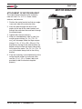
MOTOR BRACKET
ATTACHMENT OF MOTOR BRACKET
The motor bracket attaches to the extension
tube with two 1/2 x 4-1/2 in. Grade 8 bolts,
washers, and locknuts.
1. Position the motor bracket so that one angle
is on each side of the extension tube.
2. Insert the bolts through the holes in the
angles at the top of the motor bracket and
through the extension tube and back through
the second angle.
3. Tighten both locknuts securely.
4. When an extended down tube is used, the
smaller square tubing (3 x 3 in. [75 x 75
mm]) will telescope inside the larger square
tubing (3-1/2 x 3-1/2 in. [90 x 90 mm]). The
brackets on the top of the motor bracket are
bolted in slots to allow the larger tube to bolt
to the top of the motor. The 3 x 3 in. (75 x 75
mm) tube should always bolt to the ceiling
bracket.
5. If the fan assembly is mounted directly to the
ceiling bracket without an extension tube,
use four 1/2 x 1-1/2 in. Grade 8 bolts (not
provided) to bolt the brackets together
properly.
Figure 8

RAVE®FAN
16 Pub. No. 54450034 Rev. 4 - © DECEMBER 2014
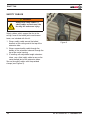
SAFETY CABLES
Safety cables, which support the fan to the
ceiling if one of the bolted joints would come
loose, are included with this kit.
1. Wrap a safety cable around the bolted
brackets at the ceiling and at the top of the
extension tube.
2. Wrap a second safety cable through the
bottom of the extension tube and through the
top of the motor housing.
3. If installing with adjustable-length extension
tubes, use a third safety cable to secure the
center bolted joint of the extension tubes.
Secure the safety cables with the provided
clamps (see Figures 9).
Figure 9
WARNING
!
!
Always use safety cables. If
safety cables are not used, the
fan may fall and cause injury.

RAVE®FAN
Pub. No. 54450034 Rev. 4 - © DECEMBER 2014 17
INSTALLATION
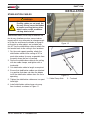
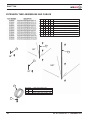
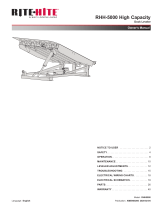
STABILIZATION CABLES
Stabilization cables, which help to stabilize the
fan for any situations such as cross winds or
impacts which may otherwise be strong enough
to tilt the fan and cause the blades to impact a
ceiling joist or other object, are included with
this kit. Use the stabilization cables to attach the
fan bracket back to the ceiling in four locations.
1. For the most support possible, attach the
stabilization cables to the ceiling at 90° to
each other and as far away as possible from
the point where the fan is mounted.
2. Secure the stabilization cables to the ceiling
with two cable clamps, and tighten with a
turnbuckle.
3. Cut stabilization cable to length as required.
4. Ensure that stabilization cables are attached
in a position that does not allow the blades
to hit the stabilization cables when the fan is
operating.
5. Tighten the stabilization cables one turn past
hand-tight.
6. Install stabilization cable clamp nuts away
from turnback, as shown in Figure 11 .
Figure 10
Figure 11
1 – Cable Clamp Nuts 2 – Turnback
1
2
WARNING
!
!
Always use stabilization cables.
If safety cables are not used, the
fan may tilt and cause the blades
to impact a ceiling joist or other
object under certain conditions
causing debris to fall.

RAVE®FAN
18 Pub. No. 54450034 Rev. 4 - © DECEMBER 2014
Figure 12
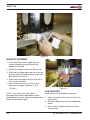
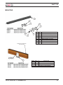
BLADE ATTACHMENT
1. Clean each blade with a paper towel to
remove fingerprints and dirt before the
blades are installed.
2. Set the fan blades in place on the fan hub.
3. Raise the fan blade above the arm of the fan
hub and allow the blade to slide into the slot
provided on the fan hub.
4. Attach each fan blade to the fan hub with a
22 mm bolt (provided).
5. Use a torque wrench with a 3/4 in. drive
extension to tighten the bolt to 75 ft-lb
(102 Nm).
NOTE: In the event that a fan blade is
damaged, both the damaged blade and the
blade opposite must be replaced. Replacement
blades are provided in pairs.
Figure 13
FAN LEVELING
Level the fan hub after blade attachment.
1. Hold a level across the center of the hub in
all directions.
2. Make fine adjustments with the stabilization
cables.
3. After run/test, go back and test level and
cable tension.

RAVE®FAN
Pub. No. 54450034 Rev. 4 - © DECEMBER 2014 19
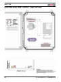
GUARDING THE FAN
Guard the fan if there is potential for a person or
object to come into contact with moving fan
blades. In some cases, this guarding can be a
structure built near the edge of the blades to keep
fork trucks and other objects from entering a
danger area. In other cases, such as when fans
are mounted on low ceilings, it may be necessary
to build a “cage” around the fan blades to ensure
objects do not come into contact with the moving
fan blades. It is best to mount this cage
independent of the fan and support the cage from
the ceiling or columns as necessary.
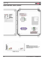
LINE REACTOR (STANDARD)
A line reactor is provided to protect the fan drive
from power line disturbances. It also reduces
harmonics created by the drive.
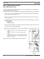
ELECTROMAGNETIC COMPATABILITY
(EMC) FILTER (OPTIONAL)
The EMC filter is an optional component used to
reduce electromagnetic interference. It should
be considered in the following applications:
1. If compliance with IEC 61800-3 C2 is
required.
2. If the fan may be affected by electrical
interference on the line ( from VFDs, welding
equipment, etc...).
3. If sensitive electronic or radio equipment is in
use that may be affected by the fan VFD.
OPEN AIR ENVIRONMENT
When fans are used in open air environments, it
is recommended that the fans be shut down
during periods of high wind speed. A wind
speed control kit is available from Rite-Hite
Fans. See page 57 for parts list and pages
33-34 for wiring diagram.
REMOTE STOP INPUT (FIRE
SUPPRESSION, WIND SENSORS,
BUILDING AUTOMATION, ETC.)
Any device with a relay output can stop the
Rave Fan remotely by opening a contact.
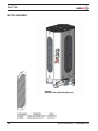
CONTROL BOX SIZE
Controls are mounted in a 16x14x8 enclosure.
Overall size is 17.6" x 16" x 8.4" (447mm x
406mm x 212mm)
WARNING
!
!
Rotating fan blades can cause
serious injury.

RAVE®FAN
20 Pub. No. 54450034 Rev. 4 - © DECEMBER 2014
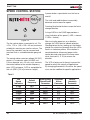
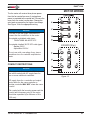
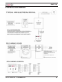
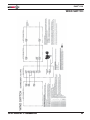
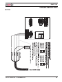
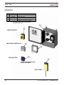
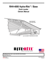
SPEED CONTROL STATION
Figure 14
The fan control station is provided in a 4.75 x
4.75 x 1.75 in. (120 x 120 x 45 mm) enclosure
suitable for mounting on a wall or column. The
face of the controller may be removed and
mounted flush in a standard double gang wall
box.
The control station uses low voltage (24 VDC)
control. A 7-conductor cable (24 AWG min/
0.5 mm diameter min, 0.2 mm^2 min) connects
the control station to the variable-frequency
drive (VFD) enclosure. CAT5 is acceptable for
this run (500 ft [152 m] maximum length).
A power button is provided to turn the fan on
and off.
The turtle and rabbit buttons incrementally
decrease and increase fan speed.
Pressing the direction button causes the fan to
change direction.
A ring of LEDs in the FANS logo provides a
visual indication of fan speed (1 LED = slowest,
7 LEDs = fastest).
After turning the power on, or a direction
change, the LEDs flash to indicate direction.
Standing below the fan, looking up, the blades
should turn clockwise (forward) when the LEDs
flash in a clockwise pattern. If the rotation is
counterclockwise, disconnect power to the
control box and swap two of the three motor
wires (terminals U, V, W) to reverse fan
direction.
The VFD is factory-set to linearly increase fan
speed to satisfy the majority of applications.
By changing parameters in the drive, the speed
curve can be modified for specific applications.
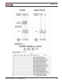
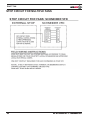
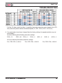
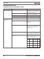
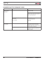
Table 5
Fan Allen Bradley Schneider AB PF4
Speed Default PowerFlex40 Altivar (obsolete)
Indication Frequency Parameter Parameter Parameter
0 LED OFF
1 LED 10Hz A077 SP8 A073
2 LEDs 18Hz A076 SP7 N/A
3 LEDs 26Hz A075 SP6 A072
4 LEDs 35Hz A074 SP5 N/A
5 LEDs 44Hz A073 SP4 A071
6 LEDs 52Hz A072 SP3 N/A
7 LEDs 60Hz A071 SP2 A070
Page is loading ...
Page is loading ...
Page is loading ...
Page is loading ...
Page is loading ...
Page is loading ...
Page is loading ...
Page is loading ...
Page is loading ...
Page is loading ...
Page is loading ...
Page is loading ...
Page is loading ...
Page is loading ...
Page is loading ...
Page is loading ...
Page is loading ...
Page is loading ...
Page is loading ...
Page is loading ...
Page is loading ...
Page is loading ...
Page is loading ...
Page is loading ...
Page is loading ...
Page is loading ...
Page is loading ...
Page is loading ...
Page is loading ...
Page is loading ...
Page is loading ...
Page is loading ...
Page is loading ...
Page is loading ...
Page is loading ...
Page is loading ...
-
 1
1
-
 2
2
-
 3
3
-
 4
4
-
 5
5
-
 6
6
-
 7
7
-
 8
8
-
 9
9
-
 10
10
-
 11
11
-
 12
12
-
 13
13
-
 14
14
-
 15
15
-
 16
16
-
 17
17
-
 18
18
-
 19
19
-
 20
20
-
 21
21
-
 22
22
-
 23
23
-
 24
24
-
 25
25
-
 26
26
-
 27
27
-
 28
28
-
 29
29
-
 30
30
-
 31
31
-
 32
32
-
 33
33
-
 34
34
-
 35
35
-
 36
36
-
 37
37
-
 38
38
-
 39
39
-
 40
40
-
 41
41
-
 42
42
-
 43
43
-
 44
44
-
 45
45
-
 46
46
-
 47
47
-
 48
48
-
 49
49
-
 50
50
-
 51
51
-
 52
52
-
 53
53
-
 54
54
-
 55
55
-
 56
56


RITE-HITE Rave RHC 1234567-001 Installation and Owner's Manual
- Type
- Installation and Owner's Manual
Ask a question and I''ll find the answer in the document
Finding information in a document is now easier with AI
Related papers
-
 RITE-HITE VBR300 DokLok Vehicle Restraint Owner's manual
-
 RITE-HITE RHH High Cap User manual
-
 RITE-HITE VBR 600 Dok Lok Vehicle Restraint Owner's manual
-
 RITE-HITE RHE3 Installation guide
-
 RITE-HITE RHJ Owner's manual
-
 RITE-HITE Z Deck Owner's manual
-
 RITE-HITE Genisys ML-900 Owner's manual
-
 RITE-HITE Barrier Glider Cold Storage Door Owner's manual
-
 RITE-HITE RHH-5000 Owner's manual
-
 RITE-HITE RHH Hydrualic Owner's manual


Other documents
-
STARMOBILE Up Rave Hard reset manual
-
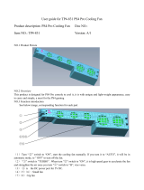 doBe TP4-831 User manual
-
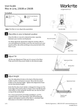 Workrite Ergonomics Rite-In-Line™ Document Holder User guide
-
Schneider Electric ATV340 Installation guide
-
FloAire F-HVLS Fansand Controls Operation & Installation Manual
-
-
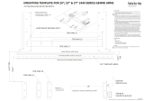 Workrite Ergonomics 20”, 23”, 27” 2440 Series Gemini™ Arms Mounting Template
-
 Northern Tool 36012763 Owner's manual
-
Clipsal Airflow Ceiling Sweep Fans User manual
-
 J D Manufacturing VG24DM Whirl-Wind Galvanized Box Fan User manual


