Clipsal Airflow Ceiling Sweep Fans User manual

Type
User manual

Clipsal Airflow Ceiling Sweep Fans are designed to provide reliable and efficient air circulation in both residential and commercial spaces. With their powerful motors and aerodynamic blades, these fans deliver a refreshing breeze, ensuring optimal comfort levels even in large rooms. Featuring a range of models with different blade sizes, finishes, and light integration options, these fans offer a customizable solution to suit any interior design and lighting needs.

Clipsal Airflow Ceiling Sweep Fans are designed to provide reliable and efficient air circulation in both residential and commercial spaces. With their powerful motors and aerodynamic blades, these fans deliver a refreshing breeze, ensuring optimal comfort levels even in large rooms. Featuring a range of models with different blade sizes, finishes, and light integration options, these fans offer a customizable solution to suit any interior design and lighting needs.

Included with your Fan
23606_F2365 Airflow Ceiling Sweep Fan A4 PRESS.indd 1 21/09/2011 11:30:12 AM
Installation Instructions
REGISTERED DESIGN • REGISTERED PATENT
Included with Your Fan
A. Motor assembly
B(i). Three blades (3HS1200)
B(ii). Four blades (4HS1200)
C. R.F. remote controller
Airflow®
Ceiling Sweep Fans
3HS1200ALR, 3HS1200SSR,
4HS1200ALR, 4HS1200SSR
Series
Thank you for purchasing this Airflow Ceiling Sweep Fan. You can be assured
of trouble free operation by installing your ceiling fan in accordance to these instructions.
Please read all the instructions before commencing, then complete each step in order.
Hangsure bracket 1.0 Mounting the Fan Support Bracket
Hangsure mounting
D.
This fan has been supplied with a remote controller that is
designed to operate a single or multiple fan, and includes on/off
control for light fittings.
D. Screw pack
E. Mounting bracket
F. Instruction sheet
Controlling a Single Fan or Multiple Fans
B(i).
B(ii).
A.
C. F.
E.
Protecting the Fan
Installation Instructions
REGISTERED DESIGN • REGISTERED PATENT
You can control up to eight Airflow Fans using a Clipsal
C-ThruTM Electronic Fan Controller (purchased separately).
NOTE: The three-speed fan controller supplied with each fan is
not suitable for controlling multiple fans.
IMPORTANT NOTES
1. To ensure proper balance, the blades are a matched set. Do
not mix up the blades with those from another fan.
2. Transport and transit handling may loosen factory fitted
cables. Please check and secure terminal screws before
installation.
All electrical work must be carried
out by a qualified electrician.
Included with your Fan
A. Motor Assembly
B. Four Blades
C. Three-Speed Fan Controller
Blades:
Minimum 2.1m
above floor.
Minimum
300mm from
other obstacles.
18.5°
Controlling a Single Fan
This fan has been supplied with a quality Clipsal Three-Speed
Controller that is designed to operate a single fan.
OFF
13
2
Multiple Fans on a Single Controller
Clearances and Angled Ceilings
Hangsure Mounting
Suitable for pitched ceilings
with a maximum angle of 18.5°.
Protecting the Fan
Do not place the motor directly onto a flat surface.
The plastic nipple underneath the motor cannot support the
weight of the motor and may be easily damaged. When working
on the fan, place the motor on the foam packaging with the
nipple located in one of the recesses. This protects the nipple
and the finish.
D. Screw Pack
E. Mounting Bracket
F. Instruction Sheet
Plastic Nipple
Foam
Packaging
Hangsure Bracket or J-Hook Bracket
Ceiling Sweep Fan
4HS1200, 4HS1400, 4JH1200, 4JH1400
Thank you for purchasing this Airflow Ceiling Sweep Fan. You can be assured of
trouble-free operation for years by installing your ceiling fan carefully and according to these instructions.
Please read all the instructions before commencing, then complete each step in order.
23606_F2365 Airflow Ceiling Sweep Fan A4 PRESS.indd 1 21/09/2011 11:30:12 AM
Foam
Packaging
NOTICE
HAZARD OF INCORRECT ASSEMBLY
To ensure proper balance, do not mix up blades with those
from another fan as they are a matched set.
Transport and transit handling may loosen factory fitted
cables. Please check and secure terminal screws before
installation
Failure to follow these instructions can result in equipment
damage
NOTICE
HAZARD OF PRODUCT DAMAGE
Do not place the motor directly onto a flat surface.
The plastic nipple underneath the motor cannot support
the weight of the motor and may be easily damaged. When
working on the fan, place the motor on the foam packaging
with the nipple located in one of the recesses. This protects
the nipple and the finish.
Failure to follow these instructions can result in equipment
damage
DANGER
HAZARD OF ELECTRIC SHOCK OR ARC FLASH
This equipment must only be installed and serviced by
appropriate qualified and/or licenced electrical personnel.
Isolate the electrical supply before doing any work on
this equipment
Ensure that the product had been correctly installed and tested
operation before reconnecting the electrical supply.
Failure to follow these instructions will result in death
or serious injury.
Ceiling Sweep Fan
23606_F2365 Airflow Ceiling Sweep Fan A4 PRESS.indd 1 21/09/2011 11:30:12 AM
Ceiling Sweep Fan
23606_F2365 Airflow Ceiling Sweep Fan A4 PRESS.indd 1 21/09/2011 11:30:12 AM
Secure fixing to support 15kg
Blades:
Minimum 2.1m
above floor.
Minimum
300mm from
other obstacles.
18.5°
Clearances and Angled Ceilings
Hangsure Mounting
Suitable for pitched ceilings
with a maximum angle of 18.5°.
WARNING
LOCATION HAZARD
Select a suitable location to mount the fan support bracket.
The mounting bracket must be fixed to a solid structural
member, such as a ceiling joist or a securely fixed noggin and
be capable of supporting 15kg.
Additionally, it must be located to provide the blade with a
minimum clearance of 2100mm from the floor, and at least
300mm from other obstructions.
Failure to follow these instructions can result in injury or
equipment damage
ACES48ALR Airflow Ceiling Sweep Fans Installation Instructions
2 of 4 © 2012 Schneider Electric. All Rights Reserved.
Light wires
Adaptor
Lamp holder
Light wires
Plastic nipple
Lift the fan up and place the
ball onto the bracket.
Make sure the guide pin of
bracket is fitted into slot of
ball-joint.
Place the blade over the motor and align screws.
Securely tighten both screws.
2.0 Fitting the Blades
3.0 Connecting the Light Fitting
If you are attaching a light fitting to the fan, do so prior to hanging
the fan.
NOTE:
Clipper Light or Oyster Light may be installed in fans which are
constructed for this purpose.
1. Unscrew the plastic nipple from the bottom of the
motor housing.
2. Pull out the light wires from the motor housing for connection
with the lamp holder.
3. Insert the light wires through the adaptor, then screw the
adaptor into the motor shaft.
4. Connect the light wires to the lamp holder then screw the
lamp holder and the adaptor together firmly.
4.0 Hanging the Fan
Hangsure bracket
Position the ball-joint in the bracket so that the guide pin on the
bracket engages in the slot in the ball-joint.
5.0 Remote Control Setup
The remote control is a 16-Channel Radio Frequency (RF) type.
To ensure correct operation of the fan, please follow this setup.
Both the remote control and the receiver have a DIP switch.
The remote control DIP switch is located in the battery
compartment and the receiver’s DIP switch is located
on the side (both as shown in diagrams).
These switches must be set to the same values on both
the remote control and the receiver, for the fan/s to
operate correctly.
Multiple channels are available so you are able to control
multiple fans individually or control a number of fans as one.
DIP switch
DIP switch
ACES48ALR Airflow Ceiling Sweep Fans Installation Instructions
2 of 4 © 2012 Schneider Electric. All Rights Reserved.
Slide blade over screws.
Foam
packaging
Support the motor. Remove plastic spacer.
A B
C
Tighten screws.
D
Guide pin
Slot
Light wires
Adaptor
Lamp holder
Light wires
Plastic nipple
Lift the fan up and place the
nylon ball onto the bracket.
Make sure the guide pin of
bracket is fitted into slot of
ball-joint.
Discard the plastic spacer, as illustrated in the diagram below.
Seat the key-slot holes of the blade on the screws of the
fan motor.
Slide the blade to the right (as illustrated) until the blade engages
in the locking mechanism, then secure the blade with screws.
2.0 Fitting the Blades
3.0 Connecting the Light Fitting
If you are attaching a light fitting to the fan, do so prior to hanging
the fan.
NOTE:
Clipper Light (CL) and Oyster Light (OL) may be installed in fans
which are constructed for this purpose.
1. Unscrew the plastic nipple from the bottom of the
motor housing.
2. Pull out the light wires from the motor housing for connection
with the lamp holder.
3. Insert the light wires through the adaptor, then screw the
adaptor into the motor shaft.
4. Connect the light wires to the lamp holder then screw the
lamp holder and the adaptor together firmly.
4.0 Hanging the Fan
Hangsure bracket
Position the ball-joint in the bracket so that the guide pin on the
bracket engages in the slot in the ball-joint.
5.0 Remote Control Setup
The remote control is a 16-Channel Radio Frequency (RF) type.
To ensure correct operation of the fan, please follow this setup.
Both the remote control and the receiver have a DIP switch.
The remote control DIP switch is located in the battery
compartment and the receiver’s DIP switch is located
on the side (both as shown in diagrams).
These switches must be set to the same values on both
the remote control and the receiver, for the fan/s to
operate correctly.
Multiple channels are available so you are able to control
multiple fans individually or control a number of fans as one.
DIP switch
DIP switch
Slide blade over screws
Foam
Packaging
Support the motor Remove plastic spacer
A B
C
Tighten screws
D
Mounting the Fan Support Bracket
Slide blade over screws
Foam
Packaging
Slide blade over screws
Foam
Packaging
Support the motor Remove plastic spacer
A B
Tighten screws
D
Mounting the Fan Support Bracket
Support the motor Motor Screw Holes
A B
C
Slide blade over screws
Foam
Packaging
Support the motor Remove plastic spacer
A B
C
Tighten screws
D
Mounting the Fan Support Bracket
Tighten screws
D
Guide Pin Slot
ACES48ALR Airflow Ceiling Sweep Fans Installation Instructions
3 of 4
© 2012 Schneider Electric. All Rights Reserved.
9.0 Operating Your Fan
Forward/reversible switch on motor housing controls
air movement.
ACES48ALR Airflow Ceiling Sweep Fans Installation Instructions
3 of 4
© 2012 Schneider Electric. All Rights Reserved.
9.0 Operating Your Fan
Forward/reversible switch on motor housing controls
air movement.
Caution: Before changing forward/reversible switch, turn
the fan OFF and ensure that the fan has stopped rotating,
to prevent injury to yourself and damage to the motor.
REMOTE CONTROL:
Use the remote control to change the speed of the fan
as well as to switch both the fan and light on and off (if a light
fitting is attached to the fan).
Replace the battery by sliding the battery compartment
panel on the remote, in the direction of the arrow. Fit one
‘9V’ battery, ensuring polarity as shown in the battery
compartment (note: batteries NOT included).
Slide on the battery compartment cover.
ALWAYS ensure that the battery compartment panel is secure.
NEVER leave the remote control in direct sunlight.
NEVER attempt to recharge primary batteries, either in a
charger or by applying heat to them. There are special
rechargeable batteries, which are clearly marked as such.
NEVER dispose of batteries in re because this can cause
them to explode.
The light can be switched on and off by pressing the light
‘ON/OFF’ button on the remote control transmitter.
The speed can be selected by pressing the ‘SPEED’ button
on the remote control transmitter:
HI - High speed
MED - Medium speed
LOW - Low speed
OFF - Off
2. Manoeuvre the canopy
into place over the mounting
bracket. Ensure that the
infrared sensor is in the
shade and not in direct
sunlight. Slide up top
cowl but allow 5-10mm
clearance. Secure with
locking screws.
6.0 Installing the Fan
1. Install the receiver to the
bracket as shown. Connect
the wires according to the
remote control wiring
instructions (page 3).
7.0 Connecting the Fan
All Clipsal Airflow Ceiling Sweep Fans are pre-wired to allow for
a light to be fitted onto the fan.
If you are not fitting a light to the fan, please disregard the light
wires. The wires are connected to the incoming wiring (as
illustrated in the below diagram).
Means for all pole disconnection must be incorporated in the
fixed wiring, in accordance with the wiring rules.
10.0 Operating Instructions
Fan ON/OFF
Fan Hi
Fan Medium
Fan Low
Light ON/OFF
Cradle Handset
8.0 Mounting the Remote Control
Mount the cradle in a convenient location. The handset can be
stored in the cradle.
NEUTRAL
ACTIVE
SUPPLY
230-249V~ 50HZ
RED
BROWN
BLUE
BROWN
BLUE
REMOTE CONTROL
RECEIVER
BROWN
BLUE
GREEN/YELLOW
BROWN
BLUE
GREEN/YELLOW
EARTH
RED
BROWN
BLUE & BLACK
TB2
RED BROWN BLUE
TO REMOTE
TO FAN
RED BROWN BLUE
BROWN BLUE
TB1
L N
2. Manoeuvre the canopy
into place over the mounting
bracket. Ensure that the
infrared sensor is in the
shade and not in direct
sunlight. Slide up top
cowl but allow 5-10mm
clearance. Secure with
locking screws.
6.0 Installing the Fan
1. Install the receiver to the
bracket as shown. Connect
the wires according to the
remote control wiring
instructions (page 3).
7.0 Connecting the Fan
All Airflow Ceiling Sweep Fans are pre-wired to allow for a light to
be fitted onto the fan.
If you are not fitting a light to the fan, please disregard the
light wires. The wires are connected to the incoming wiring as
illustrated in the below diagram.
Means for all pole disconnection must be incorporated in the
fixed wiring in accordance with the wiring rules.
10.0 Operating Instructions
Fan ON/OFF
Fan Hi
Fan Medium
Fan Low
Light ON/OFF
Cradle Handset
8.0 Mounting the Remote Control
Mount the cradle in a convenient location. The handset can be
stored in the cradle.
REMOTE CONTROL:
Use the remote control to change the speed of the fan
as well as to switch both the fan and light on and off (if a light
fitting is attached to the fan).
Replace the battery by sliding the battery compartment
panel on the remote, in the direction of the arrow. Fit one
‘9V’ battery, ensuring polarity as shown in the battery
compartment (note: batteries NOT included).
Slide on the battery compartment cover.
ALWAYS ensure that the battery compartment panel is secure.
The light can be switched on and off by pressing the light
‘ON/OFF’ button on the remote control transmitter.
The speed can be selected by pressing the ‘SPEED’ button
on the remote control transmitter:
HI - High speed
MED - Medium speed
LOW - Low speed
OFF - Off
WARNING
INJURY HAZARD
Before changing forward/reversible switch, turn
the fan OFF and ensure that the fan has stopped rotating,
to prevent injury to yourself and damage to the motor.
Failure to follow these instructions can result in injury or
equipment damage
WARNING
HAZARD OF EXPLOSION
NEVER leave the remote control in direct sunlight.
NEVER attempt to recharge primary batteries, either in a
charger or by applying heat to them. There are special
rechargeable batteries, which are clearly marked as such.
NEVER dispose of batteries in fire because this can cause
them to explode.
Failure to follow these instructions can result in injury or
equipment damage
NEUTRAL
ACTIVE
RED
BROWN
BLUE
BROWN
BLUE
BROWN
BLUE
GREEN/YELLOW
BROWN
BLUE
GREEN/YELLOW
EARTH
RED
BROWN
BLUE & BLACK
GREEN/YELLOW
PLUG & SOCKET
CONNECTION
REMOTE CONTROL
RECEIVER
ACES48ALR Airflow Ceiling Sweep Fans Installation Instructions
4 of 4 © 2012 Schneider Electric. All Rights Reserved.
Warranty
The benefits conferred by this warranty are in addition to all implied warranties, other
rights and remedies in respect of the product which the consumer has under the
Trade Practices Act and similar State and Territory Laws.
The original purchaser of this Clipsal Airflow Ceiling Sweep Fan, is provided with the
following warranty, subject to the following conditions:
Schneider Electric (Australia) Pty Ltd warrant this product for a period of three years
from the date of purchase for all parts defective in workmanship or materials. All
products used in commercial applications are limited to a 90 day warranty.
All defective parts will be replaced free of charge. The following exclusions do not
preclude the purchaser from those statutory rights consumers have under the Trade
Practices Act or similar State and Territory Laws.
WARRANTY CONDITIONS:
1. This warranty, is only valid for appliances installed according to the
manufacturers instructions.
2. This appliance must not be modified or changed in any way
and all electrical connections must be carried out by a
qualified electrician only.
3. Connection must be to the voltage requirements, as specified in the
ratings label located on the product.
4. The manufacturer does not accept liability for any direct or
consequential damage, loss or other expense arising from misuse
or incorrect installation and operation of the appliance.
5. Warranty will only be given where proof of purchase is provided,
e.g. original invoice.
6. For warranty to be valid, only Airflow accessories, such as down-rods
and light kits, shall be installed with the Clipsal Airflow Ceiling Sweep Fan.
IMPORTANT
Record this warranty information at the time of purchase, but do not send this
information unless you are making a claim or are asked to do so.
To obtain service under warranty you must retain your original purchase receipt,
service will otherwise be charged at current rates.
Model number:
Purchased from:
Name:
Address:
Postcode:
Date of purchase:
F2130/03
CLIPCOM 24691 June 2015
Schneider Electric (Australia) Pty Ltd
Contact us: clipsal.com/feedback
National Customer Care Enquiries:
Tel 1300 2025 25 Fax 1300 2025 56
Schneider Electric (Australia) Pty Ltd reserves the right to change specifications, modify
designs and discontinue items without incurring obligation and whilst every effort is made to
ensure that descriptions, specifications and other information in this catalogue are correct, no
warranty is given in respect thereof and the company shall not be liable for any error therein.
© 2012 Schneider Electric. All Rights Reserved.
Trademarks are owned by Schneider Electric Industries SAS or its affiliated companies.
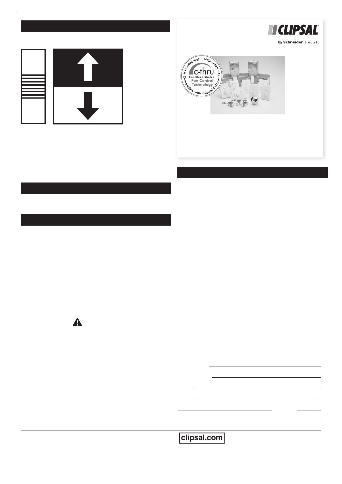
ALSO AVAILABLE FROM
C-ThruTM Electronic Fan Controllers
• Rapid Fan Start Feature.
Variable Speed Adjustment.
• Control up to Eight Airflow Fans.
• Multiple Plate Styles Available.
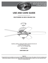
Summer/Winter Settings
The forward/reversible switch is located on the bottom cowl.
Check switch and make sure it is in correct setting, depending
on cold weather or hot weather.
Cold weather: Push switch down for the blades to circulate the
warm air trapped near the ceiling.
Hot weather: Push switch up for the blades to create a breeze
and circulate the air.
SUMMER
WINTER
Cleaning Instructions
To clean the fan, wipe over with a damp, soapy cloth.
Do not use scourers or abrasive cleaners.
For further technical support, contact the Clipsal National
Customer Service Centre on 1300 2025 25.
Troubleshooting Guide
Fan will not switch on:
Switch off the fan then check the following:
Forward/reversible switch on fan motor not fully engaged in
desired setting.
Connections not as per installation diagram.
Fuse blown, circuit breaker tripped or there is a power failure.
Check DIP switch positions to ensure the receiver matches
the controller.
Fan will not operate at varying speed control settings:
Controller connections not as per page 3.
Ticking, rattling, mechanical noises:
Ensure all screws and bolts are tight.
Ensure the mounting assembly is secure.
Ensure the lower canopy is clear of the motor.
Ensure the wires are not tapping against the canopy.
CAUTION
MOVING PARTS OR ELECTRICAL HAZARD
Do not attempt to stop the blades by hand, even at low speed.
This appliance is not intended for use by persons (including
children) with reduced physical, sensory or mental capabilities, or
lack of experience and knowledge, unless they have been given
supervision or instruction concerning use of the appliance by a
person responsible for their safety. Children should be supervised
to ensure that they do not play with the appliance.
Ensure all electrical supplies are disconnected before cleaning,
maintenance and attachment of lamp kit.
Failure to follow these instructions can result in injury or
equipment damage
  • Page 1 1
  • Page 2 2
  • Page 3 3
  • Page 4 4

Clipsal Airflow Ceiling Sweep Fans User manual

Type
User manual

Clipsal Airflow Ceiling Sweep Fans are designed to provide reliable and efficient air circulation in both residential and commercial spaces. With their powerful motors and aerodynamic blades, these fans deliver a refreshing breeze, ensuring optimal comfort levels even in large rooms. Featuring a range of models with different blade sizes, finishes, and light integration options, these fans offer a customizable solution to suit any interior design and lighting needs.

Ask a question and I''ll find the answer in the document

Finding information in a document is now easier with AI