Page is loading ...

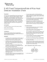
FP-11 FirePrint
™
Detector
• Most Sophisticated “Detector Intelligence” available today
• Multi-Criteria fire detection for the price of a
photoelectric detector
• FirePrint™ Technology to discriminate between deceptive
phenomena and an actual fire
• Easily programmed to match specific hazard profiles from the
control panel
• Pre-Alarm reporting based on fire profile selected
• Remote sensitivity measurement capability
• System logic activation based on any of three inputs from
detector (smoke, heat or neural network)
• Field cleanable chamber with replaceable chamber
parts available
• Multi-color detector status LED
• Two-wire operation
• Compatible with Model DPU or FPI-32 field
programmer/tester
• Supports EnviroLINK software based automatic
environmental compensation
• Backward compatible with older MXL systems
(Rev. 2 and above)
• Optional fully programmable relay base , audible base, and
duct housing
• UL Listed, ULC Listed, CSFM, FM, NYMEA
Approved
6175
CATALOG NUMBER
Intelligent Fire Detector for MXL, MXL-IQ, and MXLV Control Panels
Introduction
The FP-11 Intelligent Fire Detector provides the life
safety industry with the most highly evolved detection
system available today. The FP-11 utilizes advanced
detection technology that allows the detector to
distinguish nonthreatening deceptive phenomena, such
as cigarette smoke, from actual fire hazards, while
optimizing detection for the area in which it is in-
stalled. No other detection system available today
offers a higher level of protection or nuisance
alarm immunity. The FP-11 uses state-of-the-art
microprocessor circuitry with error check, detector
self-diagnostics and supervision programs.
The FP-11 intelligent fire detector is compatible with
the Siemens Building Technologies, Fire Safety Divi-
sion, Model DPU or FPI-32 field programmer/tester,
which is a compact, portable, menu-driven accessory
for electronically programming and testing detectors,
easily and reliably. The DPU or FPI-32 eliminates the
need for cumbersome, unreliable mechanical program-
ming methods and reduces installation and service
costs by electronically programming and testing the
detector prior to installation.
The FP-11 fire detector is compatible with the MXL
family of control panels including the MXL, MXL-IQ,
and MXLV.
The FP-11 detector is Underwriters Laboratories and
Underwriters Laboratories of Canada Listed.
Description
The FP-11 is a plug-in, two-wire, multi-sensor detector
with both photoelectric and thermal inputs and is
compatible with the MXL family of control panel
systems. Each detector consists of a dust resistant,
field cleanable photo chamber, a solid state

non-mechanical thermal sensor, microprocessor based
electronics with a low-profile plastic cover and base.
The FP-11 utilizes state-of-the-art ASIC and surface
mount technology for maximum reliability. Every FP-11
fire detector is shipped with a protective dust cover.
The FP-11 fire detector utilizes an infrared light
emitting diode (IRLED), and light sensing photodiode.
Under normal conditions, light transmitted by the LED
is directed away from the photodiode and scattered
through the smoke chamber in a controlled pattern.
The smoke chamber is designed to manage light
dissipation and extraneous reflections from dust
particles or other non-smoke airborne contaminants in
such a way as to maintain stable, consistent detector
operation. When smoke enters the detector chamber,
light emitted from the IRLED is scattered by the
smoke particles and is received by the photodiode.
The FP-11 also utilizes a modern, accurate, shock-
resistant thermistor to sense temperature changes.
The “on-board” FirePrint technology allows the
detector to gather smoke and thermal data, and to
analyze this information in the detector’s “neural
network”. By comparing data received with the
common characteristics of fires, or fire fingerprints,
the FP-11 can compare these “Fire Prints” to those of
deceptive phenomena that cause other detectors to
alarm. The advanced FirePrint technology allows the
FP-11 to accurately determine a true fire hazard from
a nonthreatening deceptive phenomena WITHOUT
needing to use alarm delaying verification and confir-
mation techniques, which can increase the probability
of losses due to fire.
The FP-11 provides the highest level of detector
intelligence available today with a detector/control
panel link that allows the user to program the detector
for the specific hazard profile Detectors are optimized
by selecting one of the following applications:
• Office/Retail
• Lobby
• Computer Room
• Dormitory
• Healthcare
• Parking Garage
• Utility/Transformer Room
• Hostile Environment
• Precious Storage
• Air Duct
• Warehouse/Light Manufacturing
The software does the rest; no guessing on detector
sensitivities or alarm verification; the control panel
programs the FP-11 detector for the protected area
without hassle and without confirmation delays.
Once optimized for the hazards in the protected area,
the FP-11 provides the best detection you can buy.
Should the operator or installer forget to program the
detector, the FP-11 will revert to a default setting that
allows it to operate as a standard photoelectric or
photothermal detector.
The FP-11’s FirePrint technology monitors input from
both the photo chamber and the thermal sensor,
evaluating this information with sophisticated
mathematical formulas, or algorithms, comparing this
input to characteristics of both threatening fires and
deceptive phenomena that would “fool” any ordinary
detector. This technology was developed over years of
research and reviewing the results of over 20 years of
fire test data in one of the world’s most advanced fire
research centers. The results of this research are the
mathematical models that form the algorithms used in
FirePrint. No other fire detector has this level of
intelligence or this amount of research and develop-
ment supporting it’s design.
The microprocessor’s software can identify and
disregard false input caused by radio frequency (RFI)
and electromagnetic (EMI) interference, and validates
all trouble conditions before annunciating or reporting
to the control panel. The FP-11 detector’s microproces-
sor uses an integral EEPROM to store the detector’s
address and other critical operating parameters which
include the assigned program values for alarm and
trouble thresholds. Communications within the
detector itself and between the FP-11 and the control
panel, or with the FPI-32 field programmer/tester, are
supervised and safeguarded against disruption by
reliable, microprocessor based error checking routines.
Additionally, the microprocessor supervises all
EEPROM memory locations and provides a high
degree of EEPROM failure fault tolerance.
In MXL(V) applications, the FP-11 determines its
operating status to be normal, in alarm, or in trouble
depending on the difference between the alarm
threshold values stored in the detector’s memory and
the detector’s latest analog measurement. The
detector then communicates changes in its status to
the control panel.
In addition, the MXL(V) control panel will sample the
value of the FP-11’s analog signal over a period of time
in order to determine if those values indicate exces-
sive buildup in the photo chamber; if so, the MXL(V)
will indicate that the particular detector requires
maintenance.
The FP-11 is listed as a self-testing device. The FP-11’s
visible light emitting diode (LED) flashes green every
4 seconds to indicate it is communicating with the
control panel and that it has passed its internal self-
test. Should the detector sense a fault or failure within
its systems, the LED will flash amber and the detector
will transmit that information to the control panel.
A quick visual inspection is sufficient to indicate the
condition of the detector at any time. If more detailed
information is required, a printed report can be
provided from the MXL panel indicating the status
and settings assigned to each individual detector.
When the FP-11 moves to the alarm mode, it will flash
amber and transmit that information to the control
panel. When the MXL(V) confirms the detectors
condition, the panel will instruct the FP-11 to flash red
and to continue flashing until the system is reset at
the control panel. At that same time, any user defined

system alarm functions programmed into the system
are activated. Each FP-11 detector can operate one
remote alarm indicator, one auxiliary relay, or one
audible base.
Detector sensitivity, calibration, and identification are
dynamically supervised by the control panel. Detector
sensitivity and pre-alarm levels are a function of the
application chosen at the control panel and are
controlled by the panel. If an alternate, non-FirePrint
mode is selected, then the sensitivity can be changed
from the control panel.
The DPU or FPI-32 Program/Test accessory is used to
program and verify the detector’s address. The
technician selects the accessory’s program mode to
enter the desired address. The DPU or FPI-32 auto-
matically sets and verifies the address and tests the
detector. It also allows the user to change the device
ID from that of an FP-11 to an older detector ID such as
an ILP-1, ILPT-1, ILP-2, ID-60P or ID-60PT to allow for
easy replacement of older detectors without the need
of reprogramming the control panel.
The FPI-32 operates on AC power or rechargeable
batteries, providing flexibility and convenience in
programming and testing equipment almost anywhere.
When in the test mode, the DPU or FPI-32 will perform
a series of diagnostic tests without altering the
address or other stored data, allowing technicians to
determine if the detector is operating properly.
The FP-11 fire detector may be installed on the same
initiating circuit with IL or ID series detectors (Photo-
electric, thermal, or ionization), MSI series manual
stations, TRI series interfaces, ICP output control
devices, or CZM series of addressable, conventional
zone modules.
All FP-11 detectors can be cleaned in the field, when
required, by simply removing the detector cover and
unsnapping the photo chamber. There is also the
option of cleaning the interior of the detector with a
clean, soft cloth or brush, or replacing the labyrinth and
bug screen included in the detector maintenance kit,
model DMK-11.
The FP-11 uses the low profile surface mounting base,
model DB-11. This base mounts on a 4-inch octagon,
square, or a single gang electrical box. The base
utilizes screw clamp contacts for electrical connections
and self-wiping contacts for increased reliability. The
base can be used with the optional LK-11 detector
locking kit which contains 50 detector locks and an
installation tool, to prevent unauthorized removal of
the detector head. The DB-11 base has integral decora-
tive plugs to cover the outer mounting screw holes.
The FP-11 is electrically compatible with existing MXL
detector accessories including relays, remote lamps,
duct housings, and audible bases. With duct housings,
a base adapter and new detector housing cover are
required (order AD-11UK upgrade kit). To use existing
DB-3S base or audible base, the FP-11 requires a DB-
ADPT base adapter.
All FP-11 detectors are approved for operation within
the UL specified temperature range of 32 to 100
degrees F (0 to 38 degrees C).
Application Data
Installation of the FP-11 series of fire detectors
requires a two-wire circuit of 18 AWG (minimum)
thermoplastic fixture wire enclosed in conduit, or 18
AWG limited energy, shielded cable without conduit,
if permitted by local codes. Field wiring should
conform to local and National Electric Codes and the
control panel wiring specifications.
“T-tapping” is permitted only for Style 4 (Class B)
wiring.
FP-11 fire detectors can be applied within the maxi-
mum 30 foot center spacing (900 sq. ft. areas) as
referenced in NFPA 72. This applications guideline is
based on ideal conditions, specifically, smooth ceiling
surfaces, minimal air movement, and no physical
obstructions between potential fire sources and the
detector. Do not mount detectors in close proximity
to ventilation or heating and air conditioning outlets.
Exposed joints or beamed ceilings may also affect safe
spacing limitations for detectors. Should questions
arise regarding detector placement, observe NFPA
72 guidelines.
Good fire protection system engineering and common
sense dictate how and when fire detectors are
installed and used. Contact your local Siemens
Building Technologies, Fire Safety Division authorized
sales outlet whenever you need assistance applying
FirePrint in unusual applications. Be sure to follow
NFPA guidelines, UL/ULC approved installation
instructions, which are included with every detector,
and local codes as for all fire protection equipment.
Dimensions

Ordering Information
Technical Specifications
Current Requirements: Normal 750 μa Alarm 750 μa
Operating Temperature: +32°F (0°C) to 100°F (38°C)
per UL 268/268A
Humidity: 0-93% Relative Humidity
Non-Condensing
May 2006
Supersedes sheet dated 6/03
Siemens Building Technologies
Fire Safety
Fire Safety
8 Fernwood Road
Florham Park, NJ 07932
Tel: (973) 593-2600
FAX: (973) 593-6670
Website: www.sbt.siemens.com/fis
5/06
10 M
SFS-IG
Printed in U.S.A.
Fire Safety
2 Kenview Boulevard
Brampton, Ontario
Canada L6T 5E4
Tel: (905) 799-9937
FAX: (905) 799-9858
/