Page is loading ...

INSTRUCTION MANUAL
CSIM11 pH and ORP Probes
Revision: 3/15
Copyright © 2000- 2015
Campbell Scientifi
c, Inc.


Limited Warranty
The CSIM11 pH and ORP Probes are warranted for six (6) months subject to
this limited warranty:
“Products manufactured by CSI are warranted by CSI to be free from defects in
materials and workmanship under normal use and service for twelve months
from the date of shipment unless otherwise specified in the corresponding
product manual. (Product manuals are available for review online at
www.campbellsci.com.) Products not manufactured by CSI, but that are resold
by CSI, are warranted only to the limits extended by the original manufacturer.
Batteries, fine-wire thermocouples, desiccant, and other consumables have no
warranty. CSI’s obligation under this warranty is limited to repairing or
replacing (at CSI’s option) defective Products, which shall be the sole and
exclusive remedy under this warranty. The Customer assumes all costs of
removing, reinstalling, and shipping defective Products to CSI. CSI will return
such Products by surface carrier prepaid within the continental United States of
America. To all other locations, CSI will return such Products best way CIP
(port of entry) per Incoterms ® 2010. This warranty shall not apply to any
Products which have been subjected to modification, misuse, neglect, improper
service, accidents of nature, or shipping damage. This warranty is in lieu of all
other warranties, expressed or implied. The warranty for installation services
performed by CSI such as programming to customer specifications, electrical
connections to Products manufactured by CSI, and Product specific training, is
part of CSI's product warranty. CSI EXPRESSLY DISCLAIMS AND
EXCLUDES ANY IMPLIED WARRANTIES OF MERCHANTABILITY
OR FITNESS FOR A PARTICULAR PURPOSE. CSI hereby disclaims,
to the fullest extent allowed by applicable law, any and all warranties and
conditions with respect to the Products, whether express, implied or
statutory, other than those expressly provided herein.”

Assistance
Products may not be returned without prior authorization. The following
contact information is for US and international customers residing in countries
served by Campbell Scientific, Inc. directly. Affiliate companies handle
repairs for customers within their territories. Please visit
www.campbellsci.com to determine which Campbell Scientific company serves
your country.
To obtain a Returned Materials Authorization (RMA), contact CAMPBELL
SCIENTIFIC, INC., phone (435) 227-9000. After an application engineer
determines the nature of the problem, an RMA number will be issued. Please
write this number clearly on the outside of the shipping container. Campbell
Scientific’s shipping address is:
CAMPBELL SCIENTIFIC, INC.
RMA#_____
815 West 1800 North
Logan, Utah 84321-1784
For all returns, the customer must fill out a “Statement of Product Cleanliness
and Decontamination” form and comply with the requirements specified in it.
The form is available from our web site at www.campbellsci.com/repair. A
completed form must be either emailed to repair@campbellsci.com or faxed to
(435) 227-9106. Campbell Scientific is unable to process any returns until we
receive this form. If the form is not received within three days of product
receipt or is incomplete, the product will be returned to the customer at the
customer’s expense. Campbell Scientific reserves the right to refuse service on
products that were exposed to contaminants that may cause health or safety
concerns for our employees.

Precautions
DANGER — MANY HAZARDS ARE ASSOCIATED WITH INSTALLING, USING, MAINTAINING, AND WORKING ON OR AROUND
TRIPODS, TOWERS, AND ANY ATTACHMENTS TO TRIPODS AND TOWERS SUCH AS SENSORS, CROSSARMS, ENCLOSURES,
ANTENNAS, ETC. FAILURE TO PROPERLY AND COMPLETELY ASSEMBLE, INSTALL, OPERATE, USE, AND MAINTAIN TRIPODS,
TOWERS, AND ATTACHMENTS, AND FAILURE TO HEED WARNINGS, INCREASES THE RISK OF DEATH, ACCIDENT, SERIOUS
INJURY, PROPERTY DAMAGE, AND PRODUCT FAILURE. TAKE ALL REASONABLE PRECAUTIONS TO AVOID THESE HAZARDS.
CHECK WITH YOUR ORGANIZATION'S SAFETY COORDINATOR (OR POLICY) FOR PROCEDURES AND REQUIRED PROTECTIVE
EQUIPMENT PRIOR TO PERFORMING ANY WORK.
Use tripods, towers, and attachments to tripods and towers only for purposes for which they are designed. Do not exceed design
limits. Be familiar and comply with all instructions provided in product manuals. Manuals are available at www.campbellsci.com or
by telephoning (435) 227-9000 (USA). You are responsible for conformance with governing codes and regulations, including safety
regulations, and the integrity and location of structures or land to which towers, tripods, and any attachments are attached. Installation
sites should be evaluated and approved by a qualified engineer. If questions or concerns arise regarding installation, use, or
maintenance of tripods, towers, attachments, or electrical connections, consult with a licensed and qualified engineer or electrician.
General
• Prior to performing site or installation work, obtain required approvals and permits. Comply
with all governing structure-height regulations, such as those of the FAA in the USA.
• Use only qualified personnel for installation, use, and maintenance of tripods and towers, and
any attachments to tripods and towers. The use of licensed and qualified contractors is highly
recommended.
• Read all applicable instructions carefully and understand procedures thoroughly before
beginning work.
• Wear a hardhat and eye protection, and take other appropriate safety precautions while
working on or around tripods and towers.
• Do not climb tripods or towers at any time, and prohibit climbing by other persons. Take
reasonable precautions to secure tripod and tower sites from trespassers.
• Use only manufacturer recommended parts, materials, and tools.
Utility and Electrical
• You can be killed or sustain serious bodily injury if the tripod, tower, or attachments you are
installing, constructing, using, or maintaining, or a tool, stake, or anchor, come in contact with
overhead or underground utility lines.
• Maintain a distance of at least one-and-one-half times structure height, 20 feet, or the distance
required by applicable law, whichever is greater, between overhead utility lines and the
structure (tripod, tower, attachments, or tools).
• Prior to performing site or installation work, inform all utility companies and have all
underground utilities marked.
• Comply with all electrical codes. Electrical equipment and related grounding devices should
be installed by a licensed and qualified electrician.
Elevated Work and Weather
• Exercise extreme caution when performing elevated work.
• Use appropriate equipment and safety practices.
• During installation and maintenance, keep tower and tripod sites clear of un-trained or non-
essential personnel. Take precautions to prevent elevated tools and objects from dropping.
• Do not perform any work in inclement weather, including wind, rain, snow, lightning, etc.
Maintenance
• Periodically (at least yearly) check for wear and damage, including corrosion, stress cracks,
frayed cables, loose cable clamps, cable tightness, etc. and take necessary corrective actions.
• Periodically (at least yearly) check electrical ground connections.
WHILE EVERY ATTEMPT IS MADE TO EMBODY THE HIGHEST DEGREE OF SAFETY IN ALL CAMPBELL SCIENTIFIC PRODUCTS,
THE CUSTOMER ASSUMES ALL RISK FROM ANY INJURY RESULTING FROM IMPROPER INSTALLATION, USE, OR
MAINTENANCE OF TRIPODS, TOWERS, OR ATTACHMENTS TO TRIPODS AND TOWERS SUCH AS SENSORS, CROSSARMS,
ENCLOSURES, ANTENNAS, ETC.


Table of Contents
PDF viewers: These page numbers refer to the printed version of this document. Use the
PDF reader bookmarks tab for links to specific sections.
1. Introduction ................................................................. 1
2. Cautionary Statements ............................................... 1
3. Initial Inspection ......................................................... 1
4. Quickstart .................................................................... 1
4.1 CSIM11 Tutorial .................................................................................. 1
4.2 CSIM11-ORP Tutorial ......................................................................... 4
5. Overview ...................................................................... 7
6. Specifications ............................................................. 8
6.1.1 pH Sensor ...................................................................................... 9
6.1.2 ORP Sensor ................................................................................... 9
7. Installation ................................................................... 9
7.1 Preparation for Use .............................................................................. 9
7.2 Orientation ........................................................................................... 9
7.3 Wiring ................................................................................................ 10
7.4 Datalogger Programming ................................................................... 10
7.4.1 Direct Measurement, Not Temperature Compensated ................ 11
7.4.2 Temperature Compensation of pH Measurement ....................... 11
8. Calibration/ORP Check ............................................. 12
8.1 pH Sensor Calibration ........................................................................ 12
8.2 ORP Check......................................................................................... 12
9. Maintenance .............................................................. 12
9.1 Replacing Reference Electrolyte ........................................................ 13
9.2 Electrode Cleaning ............................................................................. 13
10. Troubleshooting........................................................ 14
Appendices
A.
Importing Short Cut Code ...................................... A-1
A.1 Importing Short Cut Code into a Program Editor ........................... A-1
A.1.1 CRBasic Datalogger................................................................. A-1
A.1.2 Edlog ........................................................................................ A-2
i

Table of Contents
B. Example Programs .................................................. B-1
B.1 CRBasic Program ............................................................................ B-1
B.2 Edlog Programs ............................................................................... B-2
B.2.1 CR10X Program using Edlog’s Expression Editor .................. B-2
B.2.2 CR10(X) Example using Instructions Instead of Edlog’s
Expression Editor .................................................................. B-3
C. Detailed Calibration Procedure and
Manufacturer Tips ................................................. C-1
C.1 Calibration ....................................................................................... C-1
C.2 Tips and Techniques ........................................................................ C-2
Tables
7-1. CSIM11/CSIM11-ORP Wiring ......................................................... 10
7-2. 107 Wiring ........................................................................................ 10
ii

CSIM11 pH and ORP Probes
1. Introduction
The CSIM11 measures the full pH range of liquids, and the CSIM11-ORP
measures oxidation reduction potential (ORP) of liquids. They can be
submerged in water or inserted into tanks, pipelines, and open channels. The
reference solutions and bulb configuration are optimized for natural water
applications. Alternate reference solutions and bulb configurations are
available. Contact Campbell Scientific for more information.
2. Cautionary Statements
• READ AND UNDERSTAND the Precautions section at the front of this
manual.
• Do not store the sensor in distilled water, as the gel layer will become
depleted. If this happens, the gel layer can often be rehydrated by soaking
the sensor in the pH 4 buffer solution overnight.
3. Initial Inspection
• Remove the CSIM11 or CSIM11-ORP from its package and check that it
is undamaged. If damaged, contact your supplier for replacement.
• Care should be taken when unpacking and handling all electrodes.
• The probes are shipped with a wetting cap covering the measuring end.
This cap contains a solution of pH 4 buffer saturated with potassium
chloride (KCl).
4. Quickstart
Short Cut is an easy way to program your datalogger to measure the CSIM11
and CSIM11-ORP and assign datalogger wiring terminals. Use the following
procedures to get started.
4.1 CSIM11 Tutorial
A temperature measurement is required. For this tutorial, the 107-
L thermistor is used.
1. Install Short Cut by clicking on the install file icon. Get the install file
from either www.campbellsci.com, the ResourceDVD, or find it in
installations of LoggerNet, PC200W, PC400, or RTDAQ software.
NOTE
1

CSIM11 pH and ORP Probes
2. The Short Cut installation should place a Short Cut icon on the desktop of
your computer. To open Short Cut, click on this icon.
3. When Short Cut opens, select New Program.
4. Select Datalogger Model and Scan Interval (default of 5 seconds is
alright for most applications). Click Next.
2

CSIM11 pH and ORP Probes
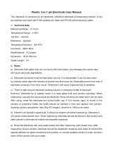
5. Under the Available Sensors and Devices list, select the Sensors |
Temperature folder. Select 107 Temperature Probe. Click to
move the selection to the Selected device window. Use the data default of
degree Celsius.
6. Under the Available Sensors and Devices list, select the Sensors | Water |
Quality folder. Select CSIM11 pH Probe. Click to move the
selection to the Selected device window. Click on the Solution
temperature (Deg C) reference box and select T107_C. The probe
usually requires an offset adjustment. The white panel at the bottom of the
Properties window provides a procedure for determining the value that
should be entered in the Offset box.
3

CSIM11 pH and ORP Probes
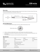
7. After selecting the sensors, click at the left of the screen on Wiring
Diagram to see how the sensor is to be wired to the datalogger. The
wiring diagram can be printed out now or after more sensors are added.
8. Select any other sensors you have, then finish the remaining Short Cut
steps to complete the program. The remaining steps are outlined in Short
Cut Help, which is accessed by clicking on Help | Contents |
Programming Steps.
9. If LoggerNet, PC400, or PC200W is running on your PC, and the PC to
datalogger connection is active, you can click Finish in Short Cut and you
will be prompted to send the program just created to the datalogger.
10. If the sensor is connected to the datalogger, as shown in the wiring
diagram in step 7, check the output of the sensor in the datalogger support
software data display to make sure it is making reasonable measurements.
4.2 CSIM11-ORP Tutorial
1. Install Short Cut by clicking on the install file icon. Get the install file
from either www.campbellsci.com, the ResourceDVD, or find it in
installations of LoggerNet, PC200W, PC400, or RTDAQ software.
4

CSIM11 pH and ORP Probes
2. The Short Cut installation should place a Short Cut icon on the desktop of
your computer. To open Short Cut, click on this icon.
3. When Short Cut opens, select New Program.
4. Select Datalogger Model and Scan Interval (default of 5 seconds is
alright for most applications). Click Next.
5

CSIM11 pH and ORP Probes
5. Under the Available Sensors and Devices list, select the Sensors | Water
| Quality folder. Select CSIM11 ORP Probe. Click to move the
selection to the Selected device window. The probe usually requires an
offset adjustment. The white panel at the bottom of the Properties
window provides a procedure for determining the value that should be
entered in Offset box.
6. After selecting the sensors, click at the left of the screen on Wiring
Diagram to see how the sensor is to be wired to the datalogger. The
wiring diagram can be printed out now or after more sensors are added.
6

CSIM11 pH and ORP Probes
7. Select any other sensors you have, then finish the remaining Short Cut
steps to complete the program. The remaining steps are outlined in Short
Cut Help, which is accessed by clicking on Help | Contents |
Programming Steps.
8. If LoggerNet, PC400 or PC200W is running on your PC, and the PC to
datalogger connection is active, you can click Finish in Short Cut and you
will be prompted to send the program just created to the datalogger.
9. If the sensor is connected to the datalogger, as shown in the wiring
diagram in step 6, check the output of the sensor in the datalogger support
software data display to make sure it is making reasonable measurements.
5. Overview
The CSIM11 and CSIM11-ORP are manufactured by Wedgewood Analytical,
Inc. and wired by Campbell Scientific. They have a plunger-style pH glass
electrode that allow them to be mounted at any angle. Their porous
polytetrafluoroethylene (PTFE) liquid junction is less susceptible to clogging
as compared to conventional reference junctions.
The outer body is made of polyphenylene sulfide (PPS). A titanium ground
rod runs inside their PPS outer body to eliminate ground loop errors. An
internal amplifier boosts the signal, decreasing signal interference. The
amplifier is powered by two internal lithium batteries, and thus does not
require any power from the datalogger. These batteries are designed to last the
lifetime of the sensors. The life expectancy of these probes is between 6
months to 2 years, depending on the conditions of the water.
These probes are intended for non-pressurized systems and were not designed
for applications above 30 psi. Please contact a Campbell Scientific water
resources application engineer for recommendations on probes suitable for
installations in pressurized pipes.
The CSIM11-ORP probe is identical to the CSIM11 pH probe except the
measuring electrode uses a large surface area platinum band, making the probe
responsive to the electron activity in the fluid. The platinum band helps
prevent organic coating, a common source of error in many types of sensors.
The practical range of the probe is –700 to +1100 mV, which is also the
approximate range of ORP in natural and runoff waters.
Platinum ORP probes should not be used for ozone or peroxide applications,
where platinum will act as a catalyst and the expected potential will not form in
the case of low concentrations. The use of gold, rather than platinum, is
suitable in these applications.
7

CSIM11 pH and ORP Probes
6. Specifications
Features:
• Internal amplifier boosts the signal, decreasing signal interference
• Titanium ground rod runs inside the outer body to eliminate ground
loop errors
• Porous PTFE liquid junction (patent number 4,128,468) is less
susceptible to clogging as compared to conventional reference
junctions
• Plunger-style pH glass electrode (patent number 4,333,812) allowing
the probe to be mounted at any angle
• Compatible with Campbell Scientific CRBasic dataloggers: CR800
series, CR1000, CR3000, CR5000, and CR9000(X). Also compatible
with Edlog dataloggers: CR500, CR510, CR10(X), CR7, 21X, and
CR23X
Temperature Range: 0 to +80 °C
Pressure Range: 0 to 30 psig (mounting to pressurized pipes or
tanks requires a non-refillable variation of the
sensor. Contact Campbell Scientific for
details)
Accuracy: ±0.1% over full range
Impedance: < 1 MΩ @ 25 °C
Reference Cell: Single Junction KCl/AgCl
Body Material: ABS
Wetted Materials: ABS, PTFE, FKM, Glass, Titanium
Cable Jacket Material: polyurethane
Response Time: 95% of reading in 10 s
Threading is
3/4 inch NPT
male
8

CSIM11 pH and ORP Probes
Drift: < 2 mV per week
Power: Two 3 Vdc lithium batteries that should last the
lifetime of the sensor
Length: 17.8 cm (7.0 in)
Diameter: 3.0 cm (1.2 in)
Weight with 15 ft cable: 0.5 kg (1 lb)
6.1.1 pH Sensor
pH Range: 0 to 14
Zero Potential: 7.0 pH ±0.2 pH
Sodium Error: < 0.05 pH in 0.1 Molar Na+ ion at 12.8 pH
Output: ±59 mV/pH unit
6.1.2 ORP Sensor
ORP Range: –700 to +1100 mV
7. Installation
If you are programming your datalogger with Short Cut, skip Section 7.3,
Wiring
(p. 10), and Section 7.4, Datalogger Programming (p. 10); Short Cut does
this work for you. See Section 4, Quickstart
(p. 1), for a Short Cut tutorial.
7.1 Preparation for Use
All electrodes are shipped with a wetting cap covering the measuring end. This
cap contains a solution of pH 4 buffer saturated with potassium chloride (KCl).
Remove the wetting cap before calibration. There may be some dry KCl
crystals forming on the outside of the cap. These deposits are expected over
time and can be wiped or rinsed off. Save the cap for future long-term storage.
Rinse the electrode with distilled water and it is ready for use.
Do not store the sensor in distilled water, as the gel layer will become depleted.
If this happens, the gel layer can often be rehydrated by soaking the sensor in
the pH 4 buffer solution overnight.
7.2 Orientation
The CSIM11/CSIM11-ORP can be installed without regard to orientation.
Unlike other pH/ORP sensors, the problem with air bubbles adversely affecting
the measurement has been eliminated by Wedgewood Analytical’s use of a
gelled reference solution and a patented plunger technology.
9

CSIM11 pH and ORP Probes
7.3 Wiring
The CSIM11 and CSIM11-ORP are connected to differential channels.
Connections to Campbell Scientific dataloggers are given in TABLE 7-1.
TABLE 7-1. CSIM11/CSIM11-ORP Wiring
Color
Description
CR9000(X)
CR5000
CR3000
CR1000
CR800
CR850
CR510
CR500
CR10(X)
21X
CR7
CR23X
Red Signal Differential
High
Differential
High
Differential
High
Green Signal
Reference
Differential
Low
Differential
Low
Differential
Low
Brown Signal Ground
AG
Often Campbell Scientific’s 107 temperature probe is used to compensate for
thermal effects. TABLE 7-2 shows the connections to the 107 probe.
TABLE 7-2. 107 Wiring
Color
Description
CR9000(X)
CR5000
CR3000
CR1000
CR800
CR850
CR510
CR500
CR10(X)
21X
CR7
CR23X
Black Voltage
Excitation
EX or VX EX EX
Red Temperature
Signal
Single-ended
channel
Single-ended
channel
Single-ended
channel
Purple Signal Ground
AG
Clear Shield
G
7.4 Datalogger Programming
Short Cut is the best source for up-to-date datalogger programming code.
Programming code is needed,
• when creating a program for a new datalogger installation
• when adding sensors to an existing datalogger program
If your data acquisition requirements are simple, you can probably create and
maintain a datalogger program exclusively with Short Cut. If your data
acquisition needs are more complex, the files that Short Cut creates are a great
source for programming code to start a new program or add to an existing
custom program.
10

CSIM11 pH and ORP Probes
Short Cut cannot edit programs after they are imported and edited
in CRBasic Editor.
A Short Cut tutorial is available in Section 4, Quickstart (p. 1). If you wish to
import Short Cut code into either Edlog or CRBasic Editor to create or add to a
customized program, follow the procedure in Appendix A.1, Importing Short
Cut Code into a Program Editor
(p. A-1). Programming basics for CRBasic and
Edlog dataloggers are provided in the following sections. Complete program
examples for select dataloggers can be found in Appendix B, Example
Programs
(p. B-1).
7.4.1 Direct Measurement, Not Temperature Compensated
Make the measurement using a differential voltage instruction (VoltDiff()
instruction in CRBasic or Volt (Diff) (P2) in Edlog). An example from each
language follows. For ORP, the multiplier would be one and the offset would
be zero.
CRBasic
VoltDiff (pH,1,mV2500,1,True ,0,_60Hz,-0.01695,7)
Edlog
1: Volt (Diff) (P2)
1: 1 Reps
2: 5 2500 mV slow Range ;Use 4 for 21X
3: 1 IN Chan
4: 1 Loc [ pH ]
5: -.01695 Mult ;Mult = 1 for ORP
6: 7 Offset ;Offset = 0 for ORP
7.4.2 Temperature Compensation of pH Measurement
ORP measurements are usually not temperature compensated.
Therefore, CSIM11-ORP users can skip Section 7.4.2 since it
pertains to pH probes only.
The CSIM11 pH probe does not automatically correct temperature effects. To
compensate for temperature variations, install a submersible temperature probe
(such as Campbell Scientific’s 107 thermistor) next to the pH probe.
Temperature compensation can be calculated after the data has been retrieved
from the field datalogger, or immediately using datalogger processing
instructions. The first method requires storing the raw pH measurement and
the temperature measurement in datalogger final storage. After retrieving data,
raw values are processed to obtain compensated values. The second method is
to program the datalogger to process the raw data after each measurement
sequence. Both the raw data and the temperature corrected pH can be saved at
the user's discretion.
NOTE
NOTE
11

CSIM11 pH and ORP Probes
8. Calibration/ORP Check
8.1 pH Sensor Calibration
Calibration should be carried out according to the detailed procedure later in
this document (see Appendix C, Detailed Calibration Procedure and
Manufacturer Tips
(p. C-1)). The following paragraphs are for general
information.
The calibration should use two or more pH standards. It is recommended that
pH 7 buffer be used to check the zero point and at least an acid or alkaline
buffer, that brackets the sample’s pH value, be used to set the slope.
An electrode measuring many samples a day should be calibrated at least once
a day. The frequency of calibration will depend on the level of accuracy
required and the coating/fouling nature of the samples being measured.
Electrodes that are continuously monitoring a sample should be checked at
least once a week or whatever period experience dictates.
Grab Sample Calibration is a technique where the process electrode has been
calibrated and placed on line for some period of time. Its output is then
verified by measuring the pH of a sample with another electrode. The grab
sample should be measured as soon as possible to avoid errors caused by
changes in the sample’s temperature or changes in the samples pH due to
exposure to the atmosphere.
8.2 ORP Check
Check the ORP sensor when it’s initially deployed and after three months of
field service. To check the sensor, place it in a known millivolt solution. The
sensor manufacturer offers +230 mV and +470 mV solutions. If the sensor
reading is within ±20 mV of the millivolt value of the solution, the sensor is
operating properly.
9. Maintenance
Developing an effective maintenance schedule is incumbent on understanding
the process effects that are specific to your application. A pH sensor develops
a millivolt potential directly proportional to the free hydrogen ion
concentration in an aqueous solution. The sensor is composed of a reference
electrode and its gelled reference electrolyte, a measurement electrode exposed
to the process solution, and a porous junction that maintains electrical contact
between the two. Porous PTFE is the newest technology in reference
junctions. Wedgewood Analytical, Inc. offers a patented porous PTFE liquid
junction which is chemically inert; and is chemically compatible with virtually
all chemicals.
• High Temperature which causes 1) Faster Response / Lower Impedance;
2) Aging acceleration, Lithium Ions Leached from Membrane; 3) Short
Span
• Low Temperature which causes Slower Response / Higher Impedance
• Measurement > 10.0 pH causes Alkaline / Sodium Ion Error
12
/