
INSTRUCTIONS
®
InterMetro Industries Corporation
North Washington Street, Wilkes-Barre, PA 18705
For Product Information Call: 1-800-433-2232
Visit Our Web Site: www.metro.com
ASSEMBLY
INSTRUCTIONS
ASSEMBLY
APPROVED
California Office of Statewide
Health Planning and Development
FIXED EQUIPMENT ANCHORAGE
R-0129
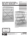
Seismic Approved Freestanding
Super Erecta
®
and Super Adjustable
Super Erecta
™
Shelving Units
BACK-TO-BACK UNIT
SINGLE UNIT

Seismic Approved Freestanding
Super Erecta
®
and Super Adjustable
Super Erecta
™
Shelving Units
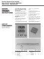
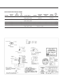
LIST OF
COMPONENTS
For the Assembly of
Seismic Shelving
NOTE: READ THE FOLLOWING
PRIOR TO ASSEMBLING YOUR
SHELVING UNIT:
Your shelving system must be
assembled as follows to accept the
Seismic Kit components correctly
and comply with OSHPD regulations:
• ASSEMBLE THE FIRST SHELF A
MAXIMUM OF 7" FROM THE
FLOOR.
• THE HIGHEST LOADED SHELF
MUST BE NO MORE THAN 60"
FROM THE FLOOR.
• IF A FIFTH SHELF IS TO BE USED,
IT MUST SERVE ONLY AS A COVER
SEISMIC
SHELVING
ASSEMBLY
INSTRUCTIONS
AND NOT AS A LOAD BEARING
SHELF.
• NO MORE THAN FOUR (4)
LOADED SHELVES ARE ALLOWED
WITHIN A 60" HEIGHT.
• THERE MUST BE A CLEARANCE
OF AT LEAST 18" BELOW
SPRINKLER SYSTEMS.
• EACH SHELVING UNIT, WHETHER
SINGLE OR BACK-TO-BACK, IS A
“STAND ALONE UNIT.” IT DOES NOT
CONNECT TO OTHER SHELVING
UNITS OR WALLS.
• SHELVING MUST BE ASSEMBLED
USING SEISMIC POSTS ONLY.
Qty.
/
Qty.
/
Qty.
/
Item Description End Kit Back Kit Kit
A. Post Clamp — — 6
B. 10-24 Screw — — 6
C. 10-24 Nut — — 6
D. Washer — — 12
E. Foot Plate — — 4
F. Sway Brace 2 2 —
Qty.
/
Qty.
/
Qty.
/
Item Description End Kit Back Kit Kit
G. Sway Brace
Clamp 4 4 —
H.
3
/8 Hex Bolt 4 4 —
I.
3
/8 Hex Nut 4 4 —
J. TEK Screw 4 4 —

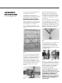
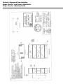
ASSEMBLY
PROCEDURE:
For the Single Unit
1. Install the square foot plates into
the bottom of each post.
Assemble your shelving unit as
described in the assembly instruction
sheet packed with the shelving.
Be certain to follow the OSHPD
regulations previously outlined.
After completing the assembly of the
shelving system, install Sway Brace
End and Back Kits as follows:
For a single freestanding unit, install
Sway Brace End Kits on each end
(Fig. 1).
Fig. 1
Fig. 2
Fig. 3
Fig. 4
Fig. 5
2. Install a Sway Brace Clamp onto
each post by spreading the clamp
and fitting it over the post. Note that
the clamps are to be installed just
above the 60" shelf position. Using
the nut and bolt supplied, attach a
Sway Brace to the clamp by inserting
the bolt through the brace and the
clamp and tighten nut securely
(Fig. 2).
3. Repeat the procedure for the
opposite side. Pivot the brace so
that it crosses the unit and attach it
to the post with Sway Brace Clamps
at the position dictated by the end
of the brace.
Install the Sway Brace Back Kit onto
the unit following the same procedure
as that for the End Kits with the
exception that the Upper clamps are
to be located just below the 60" shelf
position and the lower clamps are to
be below the lowest shelf (Fig. 3).
4. After all braces are installed, drill a
3
/
16
diameter hole in each post
through the hole in the Sway Brace
Clamp (Fig. 4) and install the TEK
screw provided to secure the clamps
to the post (Fig. 5).
5. After all assembly of the shelving
is complete, place the shelving in the
desired location and anchor the foot
plates to the floor using approved
diameter expansion anchors or
thru-bolts (not provided).
See Anchorage Specification chart.
NOTE: For OSHPD approval, the
anchorage to the structure must be
independently verified for each
installation by the Structural
Engineer of Record. The Engineer
of Record must also verify that the
structure itself is adequate for
applied loads.

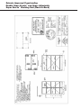
Seismic Approved Freestanding
Super Erecta
®
and Super Adjustable
Super Erecta
™
Shelving Unit
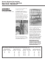
ASSEMBLY
PROCEDURE:
For the Back-to-Back Unit
1. Install the square foot plates into
the bottom of each post.
Assemble both shelving units as
described in Single Unit noting that
only one of the units will have Back
Sway Braces installed.
Position both units back to back and
clamp them together using the Post
Clamp Kits provided. The clamps are
to be positioned one near the top of
the unit, one at the bottom and one
halfway between (Fig. 6).
2. Install Sway Brace End Kits on
each end as described in the Single
Unit. Note that the braces will attach
to the outermost posts (Fig. 7).
Fig. 6
Fig. 7
3. After all assembly of the shelving
system is complete, place the
shelving in the desired location and
anchor the foot plates to the floor
using approved diameter expansion
anchors or thru-bolts (not provided).
See Anchorage Specification chart.
NOTE: For OSHPD approval, the
anchorage to the structure must be
independently verified for each
installation by the Structural Engineer
of Record. The Engineer of Record
must also verify that the structure
itself is adequate for applied loads.
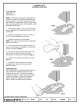
NOTE: Requirements are for
OSHPD approved shelving
installed in the state of California.
Installations outside the state of
California are subject to any state
and local codes for the location
where they are installed.
Single Unit Back Kit
Shelf Length Brace Length
24" 58
3
/8"
30" 60
7
/8"
36" 63
3
/4"
42" 67
1
/4"
48" 70
5
/8"
54" 74
5
/8"
60" 79"
HINT: Should you decide to dismantle your shelving system and move it to another location, follow the chart
to help identify an End Brace from a Back Brace when reassembling the unit.
Double Unit Back Kits
Shelf Length Brace Length
24" 58
3
/8"
30" 60
7
/8"
36" 63
3
/4"
42" 67
1
/4"
48" 70
5
/8"
54" 74
5
/8"
60" 79"
Double Unit End Kits
Shelf Widths Brace Length
18" & 18" 63
3
/4"
21" & 21" 67
1
/4"
24" & 24" 71“
18" & 21" 65
1
/2"
18" & 24" 67
1
/4"
21" & 24" 69
1
/16"
Single Unit End Kit
Shelf Widths Brace Length
18" 56
1
/2"
21" 57
3
/8"
24" 58
3
/8"

ANCHORAGE SPECIFICATION CHART
NO. DIA. FOOT
WEIGHT
/
BOLTS OF. CONCRETE EMBEDMENT WEIGHT PLATE
OPTION SQ. FT. PER POST BOLTS TYPE OF BOLTS TORQUE WEIGHT DEPTH POSTING KIT
1 30 lb./sq. ft. 1
1
/2" Kwik Bolt II or 50 ft-lb Light or 2
1
/2" Yes SAFP
Red Head Trubolt Normal SA-TAG
2 50 lb./sq. ft. 1
1
/2" Kwik Bolt II or 50 ft-lb Normal 4" No SAFP
Red Head Trubolt
3 50 lb./sq. ft. 1
5
/8" Red Head Trubolt 80 ft-lb Light 4" No SAFP
4 50 lb./sq. ft. 2
3
/8" Kwik Bolt II 25 ft-lb Normal 2
1
/2" No SAFP-2
5 50 lb./sq. ft. 1
1
/2" Kwik Bolt II or 50 ft-lb Normal at 2
1
/2" No SAFP
Red Head Trubolt Slab-on-Grade

Seismic Approved Freestanding
Super Erecta
®
and Super Adjustable
Super Erecta
™
Shelving Units

Seismic Approved Freestanding
Double Super Erecta
®
and Super Adjustable
Super Erecta
™
Shelving Unit (Back-to-Back)

®
InterMetro Industries Corporation
North Washington Street, Wilkes-Barre, PA 18705
For Product Information Call: 1-800-433-2232
Visit Our Web Site: www.metro.com
L01-152
Rev. A 5/98
Information and specifications are subject to change
without notice. Please confirm at time of order.
-
 1
1
-
 2
2
-
 3
3
-
 4
4
-
 5
5
-
 6
6
-
 7
7
-
 8
8


Ask a question and I''ll find the answer in the document
Finding information in a document is now easier with AI
Related papers
-
Metro L01-319 Operating instructions
-
-
-
-
-
-
-
-
Other documents
-
Intermetro LEC9600A Datasheet
-
-
-
Intermetro SAQHD50BP-2 Datasheet
-
Edsal PSB6500 Assembly Manual
-
-
-
 Haworth 7021-6883b Operating instructions
-
Intermetro 12WB5C Datasheet
-
