Extron IN1606 User manual

Category
Gateways/controllers
Type
User manual
1
IMPORTANT:
Go to www.extron.com for the
complete user guide, installation
instructions, and specifications.
IN1606 • Setup Guide
The Extron IN1606 Scaling Presentation Switcher is a six input, HDCP-compliant video scaler that accepts a wide variety of audio and video
formats. This guide allows an experienced user to set up and congure the IN1606. It covers how to perform basic operations using the front panel
controls and selected Simple Instruction Set (SIS™) commands.
NOTE: For full installation, configuration, menus, connector wiring, and operation details, see the IN1606 and IN1608 Series User Guide, at
www.extron.com.
Installation
Rear Panel Features
100-240V ~ 50/60 Hz
0.5 A MAX
1
2
CONFIGURABLE
HDMI
IN1606
HDMI
5
6
HDMI
A
B
3
4
INPUTS OUTPUTS AUDIO INPUTS OUTPUTS REMOTE
L1
R
L2
R
L3
R
L4
R
L5
R
+48V
+48V
12
LR
VARIABLE
Tx Rx
RS-232
G
LAN
RESET
1
2
MIC/LINE
L6
R
a bc fdeg hi
Figure 1. Rear Panel Connectors
Power and Input Connections Output Connections
Control Connections
a
AC power connector
b
Congurable analog 15-pin HD (VGA) connectors (inputs 1 and 2)
c
HDMI input connectors (inputs 3 through 6)
d
Analog audio input connectors (associated with inputs 1 through 6)
e
Mic/Line audio input connectors and adjacent phantom power LEDs
f
HDMI output connectors
g
Analog audio output connectors
h
LAN connector
i
RS-232 connector
Mounting and Cabling
Step 1 Mounting
a. Turn off or disconnect all equipment power sources.
b. Mount the IN1606 to a rack using the pre-installed rack ears (see gure 2) or remove the
rack ears and use an optional mounting kit for under-the-desk mounting (see gure 3).
Step 2 Connecting inputs
a. Connect analog video sources to the 15-pin HD connectors (see b above).
b. Connect digital HDMI or DVI (with an appropriate adapter) sources to the HDMI
connectors (see c above).
c. Connect audio input sources to the 5-pole captive screw connectors (see d above).
d. Connect Mic/Line input sources to the 3-pole captive screw connectors (see e above).
Step 3 Connecting outputs
a. Connect suitable video displays to the HDMI connectors (see f above).
b. Connect audio output devices to the 5-pole captive screw connectors (see g above).
ATTENTION: For unbalanced outputs, do not connect wires to the “-” poles
(see the IN1606 and IN1608 Series User Guide for wiring details).
Step 4 Connecting control devices
a. For control through Ethernet, connect a LAN or WAN to the RJ-45 connector
(see
h above). The default IP address is 192.168.254.254. The default subnet mask is
255.255.0.0.
b. For serial RS-232 control, connect a host device to the 3-pole captive screw connector
(see
i above). The default baud rate is 9600.
c. For control through USB, connect a host device to the front panel mini USB B port.
(see
a on page 2).
Step 5 Connecting power
Connect a 100 to 240 VAC, 50-60 Hz power source to the power AC power connector (see a above).
Figure 2. Rack Mount
Figure 3. Furniture Mount
Rack Ears
#8 Screw
(4) Places
Each Side
MBU 149
Mounting Bracket
Mounting Screws
(2) Places
Each Side
2
IN1606 • Setup Guide (Continued)
Front Panel Overview
VOLUME
SCALING PRESENTATION SWITCHER
IN1606
INPUTS
65431 2
HDCP
SIGNAL
BA
OUTPUTS
ENTER
MENU
CONFIG
213
4
56
INPUTS
a b c de f
Figure 4. Front Panel Features
a
Front panel config port Connect a host device to the mini USB B port for device conguration, control, and rmware upgrades.
b
Input selection buttons (1-6) Press one of these buttons to select an input. The buttons light amber for audio and video, green for video
only, or red for audio only.
c
Status LED indicators
Input Signal LEDs Light for the corresponding input when active video content is detected on that input.
Output Signal LEDs Remain lit green when active video is being output, or blink amber when output video and sync are disabled.
Input HDCP LEDs Light for each input signal that is HDCP-encrypted. Analog inputs 1 and 2 cannot be HDCP-encrypted.
Output HDCP LEDs Light for an output when it is currently HDCP-encrypted.
d
Menu and Enter buttons Press these buttons to access and navigate the on-screen display (OSD) menu system.
e
Navigation buttons Press these buttons to navigate through the on-screen display menu system or change selected settings.
f
Volume knob and LED indicators Rotate the Volume knob to adjust the variable analog audio output (default), mic, or program volume
(see the IN1606 and IN1608 Series User Guide to congure the knob through group masters). The eight Volume LED indicators light in order
according to the audio volume level. The bottom LED blinks when the volume is muted. They light in order from bottom to top to indicate a
12.5% increase or decrease in volume (12.5 dB) from 1% (-99 dB) to 99% (-1 dB). The top LED blinks when the volume is 100% (0 dB).
Setting Front Panel Lockout Modes (Executive Modes)
The IN1606 has two modes of front panel security lock that limit the operation of the device from the front panel.
• Executive mode 0 The front panel is fully unlocked. This is the default setting.
• Executive mode 1 The front panel is completely locked. This can only be enabled or disabled using SIS commands or the internal
web pages (see the IN1606 and IN1608 Series User Guide for web page details or the rear page of this guide for the SIS command).
• Executive mode 2 The front panel is locked except for input switching and volume control. Press and hold the Menu and Enter
buttons simultaneously for 3 seconds to enable or disable this mode.
Conguring the IN1606
The IN1606 can be congured through front panel controls and the OSD menu, the internal web pages, the Extron Product Conguration Software,
or SIS commands. To access the internal web pages or send SIS commands, connect a host device to the IN1606 via RS-232, USB, or Ethernet
connection (the internal web pages can only be accessed through an Ethernet connection).
On-Screen Display (OSD) Menu System
The IN1606 has an OSD menu consisting of nine submenus that can be accessed using the
front panel Menu or Enter button. View the menu on a display connected to either HDMI output
connector (see f on page 1). The submenus are:
Quick Setup User Presets Picture Controls Input Output
Audio Advanced Communication Device Into
To use any submenu:
1. Press the Menu or Enter button to access the main menu.
2. Press the Up or Down arrow button to navigate to the desired submenu.
3. Press the Enter or Right arrow button to access submenu items for the selected submenu.
4. Press the Up or Down arrow button to navigate submenu items.
5. Press the Enter or Right arrow button to adjust a submenu item.
Using the OSD menu to congure the IN1606
• Use the Quick Setup submenu to perform an Auto-Image™ the current input, set video input format, input EDID settings, set output
resolution, mute audio, activate video test patterns, enable or disable DHCP, and set the IP address.
• Use the User Preset submenu to save picture control settings to each input for later manual recall.
• Use the Picture Controls submenu to adjust the image position and size, brightness and contrast, color and tint, and detail as needed.
• Use the Input submenu to perform an Auto-Image on the current input, set the video input format and lm mode, set horizontal and vertical
start values, set the number of active horizontal pixels and vertical lines, set the total pixels and phase, set HDCP authorization, and set the
EDID for the current input.
• Use the Output submenu to set output resolution, HDMI output format for each output, and HDCP notication.
3
• Use the Audio submenu to mute audio, set the audio
input format for the selected input, set analog audio gain,
set mic/line gain and phantom power, adjust mic/line and
program volume, and set audio output format.
• Use the Advanced submenu to select a test pattern,
set the screen saver, turn on or off Auto-Image, set
the aspect ratio and auto memory settings, adjust
the overscan settings, and reset the device to factory
defaults.
• Use the Communication submenu to view remote port
baud rate, the device MAC address, DHCP status, the
current IP address and subnet mask, and gateway.
NOTE: Press and hold the Enter button for 10
seconds to edit settings in the Communication
submenu.
• Use the Device Info submenu to view the device
name, rmware build, temperature, input and output information, and detected displays. This tab is read-only.
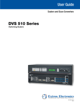
Internal Web Pages
The IN1606 can be congured, controlled, and operated
through the Ethernet port when connected to a LAN or WAN,
using a web browser. The browser displays the
factory-installed web pages, which provide a means of
conguring and operating the device. Enter the IP address
of the unit in the browser Address eld to access the web
pages (see the IN1606 and IN1608 Series User Guide for more
details). The default IP address is 192.168.254.254. The default
subnet mask is 255.255.0.0.
Product Conguration Software
To congure the IN1606 using the Product Conguration
Software, install the software (available on the Extron website,
www.extron.com) to a PC connected to the IN1606 via
Ethernet, RS-232, or front panel USB Cong port. After the
installation, start the program. For full instructions, press <F1>
or click the ? button and select Help File.
Firmware Upgrades
The onboard rmware of the IN1606 can be upgraded via the internal web pages or the Extron Firmware Loader program (available on the Extron
website, www.extron.com).
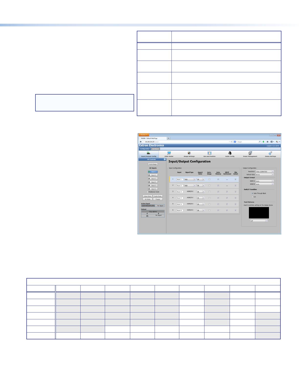
Output Rates
Output rates can be set using the OSD menu, the internal web pages, PCS, or SIS commands. The table below displays the most commonly used
resolutions and refresh rates and the corresponding SIS values. The command to set the output rate is EX5$RATE}, where X5$ is the SIS value
for the resolution and refresh rate combination as given in the example table below (see the IN1606 and IN1608 Series User Guide for the full list).
SIS Variable
X5$
for EDID or Output Resolution and Refresh Rate Combination (Where X5$ = 10 through 92)
Resolution 23.98 Hz 24 Hz 25 Hz 29.97 Hz 30 Hz 50 Hz 59.94 Hz 60 Hz 75 Hz
1024x768 19 20 21
1280x800 31 32 33
1440x900 52 53 54
1680x1050 59 60
1920x1200 63 64
720p 68 69 70 71 72 73*
1080p 77 78 79 80 81 82 83 84
* = default
Basic SIS Command Table
The IN1606 can be congured with specic SIS commands via an RS-232, USB, or Ethernet connection. Use the Extron DataViewer utility or a
control system to send and receive SIS commands. The table on the next page lists a selection of SIS commands. For a full list of SIS commands
and variables, see the IN1606 and IN1608 Series User Guide, at www.extron.com.
Audio Input
Format
Details
None Mutes all audio for selected input. Sets “No Audio” EDID.
Analog Sets the selected input to analog (default for inputs 1 and 2).
Sets “No Audio” EDID.
LPCM-2Ch Sets the selected input to LPCM-2Ch digital audio
(default for inputs 3-6). Sets 2Ch audio EDID.
Multi-Ch Sets the selected input to Multi-Ch digital audio. Sets
Multi-Ch audio EDID.
LPCM-2Ch auto Sets the selected input to prioritize digital audio. Analog
audio is passed when digital audio is not present. Sets 2Ch
audio EDID.
Multi-Ch auto Sets the selected input to prioritize digital audio. Analog
audio is passed when digital audio is not present. Sets
Multi-Ch audio EDID.
4
68-2290-50
Rev. B
06 13
Extron USA Headquarters
+1.800.633.9876 (Inside USA/Canada Only)
Extron USA - West: +1.714.491.1500 FAX: +1.714.491.1517
Extron USA - East: +1.919.850.1000 FAX: +1.919.850.1001
© 2013 Extron Electronics — All rights reserved. All trademarks mentioned are the property of their respective owners. www.extron.com
Command ASCII Command
(Host to Device)
Response
(Device to Host)
Additional Description
Select audio and video input
X!! InX!
All] Selects audio and video input X!.
Select video input only
X!& InX!
RGB] Selects the video only input X!.
Select audio input only
X!$ InX!
Aud] Selects the audio only input X!.
Execute Auto-Image
A
Img0
]
Executes Auto-Image on the current input.
Execute Auto-Image and ll
1*A
Img1
]
Executes Auto-Image and lls the output.
Execute Auto-Image and follow
2*A
Img2
]
Executes Auto-Image and maintains the aspect ratio of
the current input.
Set scaler output rate
EX5$ RATE} RateX5$]
Species an output resolution and refresh rate.
Mute video to black
1B
Vmt1
]
Mutes the video and displays a black output.
Mute video and sync
2B
Vmt2
]
Mutes the video and sync output.
Unmute video and sync
0B
Vmt0
]
Unmutes the video.
NOTE: By default, adjusting variable volume with the following commands only affects variable analog output (see the IN1606 and IN1608
Series User guide to configure the variable volume through group masters).
Set variable volume level
ED8*X4$ GRPM} GrpmD08*X4$]
Set the variable volume to a value of X4$.
Raise variable volume
ED8*X4* +GRPM}
GrpmD08*X4$]
Increase the level of the variable volume by X4* dB.
Lower variable volume
ED8*X4* -GRPM}
GrpmD08*X4$]
Decrease the level of the variable volume by X4* dB.
View variable volume level
ED8GRPM} X4$]
View the current variable volume level.
NOTE: By default, setting the audio mute with the following commands affects all outputs (see the IN1606 and IN1608 Series User guide to
configure the master audio mute through group masters).
Set master audio mute
ED7*X( GRPM} GrpmD07*X(]
Enable or disable master audio mute.
View master audio mute status
ED7GRPM} X(]
View the current master audio mute status.
Enable executive mode 1
1X
Exe1
]
Locks out the entire front panel.
Enable executive mode 2
2X
Exe2
]
Locks the front panel except for input selection and
volume control.
Disable executive modes
0X
Exe0
]
Allows all front panel adjustments and selections.
Set screen saver mode
EMX2& SSAV} SsavM X2&]
Set the screen saver mode.
Set screen saver time-out duration
ETX2# SSAV} SsavTX2#]
Set the screen saver sync time-out duration.
View screen saver status
ESSSAV} X3*]
View the status of the screen saver.
Set scaler IP address
EX4) CI} Ipi
X4)]
Species a new scaler IP address.
Set scaler DHCP mode
EX( DH} IdhX(]
Enables or disables DHCP.
Set subnet mask
EX4! CS} Ips
X4!]
Species a new subnet mask.
Set gateway IP address
EX4@ CG} Ipg
X4@]
Species a new gateway IP address.
Reboot networking
E2BOOT} Boot2]
Restarts the network after IP or DHCP changes.
NOTE: IP settings will not take effect until the E2BOOT} command is executed.
NOTES:
X! = Input selection (1-6)
X( = Enable or disable (0 = off or disabled; 1 = on or enabled)
X2# = Screen saver sync time-out duration (0 = instant time out; 1-500 = in 1 second increments; 501 = never)
X2& = Screen saver mode (1 = black output [default]; 2 = blue output)
X3* = Screen saver status (0 = active input detected; 1 = no active input, timer running; 2 = no active input, timer expired, output disabled)
X4) = IP address (xxx.xxx.xxx.xxx; 192.168.254.254 = default)
X4! = Subnet mask (xxx.xxx.xxx.xxx; 255.255.0.0 = default)
X4@ = Gateway address (xxx.xxx.xxx.xxx; 0.0.0.0 = default)
X4$ = Group volume level (-1000 to 0, where -1000 = -100 dB or 0% volume and 0 = 0 dB or 100% volume)
X4* = Increment value (dB value multiplied by ten, in 0.1 dB increments, to raise or lower a group fader [for example, 100 = 10 dB])
X5$ = Output rate (see the table on page 3 or the IN1606 and IN1608 Series User Guide)
1 / 1

Ask a question and I''ll find the answer in the document

Finding information in a document is now easier with AI

Ask the document