Page is loading ...

MW1294A28November 1996
Cage Nipple Watering
Installation & Operator’s Manual
warranty • installation • operation •
parts list • maintenance

P
a
g
e
2
•
C
a
g
e
N
i
p
p
l
e
W
a
t
e
r
i
n
g
I
n
s
t
a
l
l
a
t
i
o
n
M
a
n
u
a
l
Warranty Information
Chore-Time Equipment warrants each new product manufactured by it to be free from defects in material or
workmanship for one year from the date of initial installation by the original purchaser. If such a defect is found
by Chore-Time to exist within the one year period, Chore-Time will, at its option, (a)repair or replace such
product free of charge, F.O.B. the factory of manufacture, or (b) refund to the original purchaser the original
purchase price, in lieu of such repair or replacement.
Additional extended warranties are herewith provided to the original purchaser as follows:
1. TURBO™ and RLX™ Fans, less motors, for three years from date of installation.
*2. Poultry feeder pans that become unusable within five years from date of installation.
Warranty prorated after three years usage.
3. MEAL-TIME Hog Feeder pans that become unusable within five years of installation.
4. Rotating centerless augers, excluding applications involving High Moisture Corn
(exceeding 18%), for ten years from date of installation. Note: MULTIFLO and
applications involving High Moisture Corn are subject to a one year warranty.
5. Chore-Time manufactured roll-formed steel auger tubes for ten years from date of
installation.
*6. Laying cages that become unusable within ten years. Warranty prorated after three years
usage.
*7. ULTRAFLO Auger and ULTRAFLO Feed Trough (except ULTRAFLO Trough
Liners) are warranted for a period of five (5) years from date of original purchase against
repeated breakage of the auger or wear-through of the feed trough caused solely by the
auger.
Conditions and limitations:
1. The product must be installed and operated in accordance with instructions published by
Chore-Time or warranty will be void.
2. Warranty is void if all components of a system are not supplied by Chore-Time.
3. This product must be purchased from and installed by an authorized Chore-Time dealer or
certified representative thereof, or the warranty will be void.
4. Malfunctions or failure resulting from misuse, abuse, negligence, alteration, accident, or
lack of proper maintenance shall not be considered defects under this warranty.
5. This warranty applies only to systems for the care of poultry and livestock. Other
applications in industry or commerce are not covered by this warranty.
Chore-Time shall not be liable for any consequential or special damage which any purchaser may suffer or claim
to have suffered as a result of any defect in the product. "Consequential" or "special damages" as used herein
include, but are not limited to, lost or damaged products or goods, costs of transportation, lost sales, lost orders,
lost income, increased overhead, labor and incidental costs and operational inefficiencies.
THIS WARRANTY CONSTITUTES CHORE-TIME’S ENTIRE AND SOLE WARRANTY AND CHORE-TIME
EXPRESSLY DISCLAIMS ANY AND ALL OTHER WARRANTIES, INCLUDING, BUT NOT LIMITED TO,
EXPRESS AND IMPLIED WARRANTIES AS TO MERCHANTABILITY, FITNESS FOR PARTICULAR
PURPOSE SOLD AND DESCRIPTION OR QUALITY OF THE PRODUCT FURNISHED HEREUNDER.
Any exceptions to this warranty must be authorized in writing by an officer of the company. Chore-Time reserves
the right to change models and specifications at any time without notice or obligation to improve previous models.
*See separate Chore-Time Cage Wire Warranty as to these products.
CHORE-TIME EQUIPMENT, A Division of CTB, Inc.
P.O. Box 2000, Milford, Indiana 46542-2000 U.S.A.

P
a
g
e
3
•
C
a
g
e
N
i
p
p
l
e
W
a
t
e
r
i
n
g
I
n
s
t
a
l
l
a
t
i
o
n
M
a
n
u
a
l
Table of Contents
Topic Page User*
Warranty Information....................................................................................................2 C, D
Support Information......................................................................................................4 C, D
Tools Required.............................................................................................................4 C, D
Miscellaneous Components .........................................................................................5 C, D, I
General Information......................................................................................................5 C, D, I
Planning the System Layout.........................................................................................6 - 7 C, D, I
Installing the Cage Nipple Watering System................................................................8 - 18 I
Stand Locations ..................................................................................................................8 - 9 C, D, I
Wire Clip Locations.............................................................................................................9 C, D, I
Stand Installations...............................................................................................................9 C, D, I
Wire Clip Installations..........................................................................................................9 - 10 C, D, I
Slop Compensators Installation (optional equipment).........................................................11 C, D, I
Mid-Line Air Remover Installation (optional equipment.......................................................12 - 13 C, D, I
Motor Location Installation..................................................................................................14 C, D, I
Pressure Regulator Assembly Procedure...........................................................................14 - 15 C, D, I
Inlet End Assembly .............................................................................................................15 - 16 C, D, I
Common Flush End Installation (preferred drain system)...................................................17 C, D, I
Hose Flush End Installation (alternative dray system)........................................................18 C, D, I
Parts Listings................................................................................................................20 - 23 C, D, I
15 - 45 P.S.I. Regulator (Part No. 37147-5)........................................................................20 C, D, I
4 - 14 P.S.I. Regulator.........................................................................................................21 C, D, I
Cage Nipple Waterer Miscellaneous Components .............................................................22 - 23 C, D, I
Common Flush Drain Components.....................................................................................24 C, D, I
Hose Flush Drain Components...........................................................................................24 C, D, I
Operations Guidelines..................................................................................................25 C, D, I
Troubleshooting Guidelines..........................................................................................25 C, D, I
SURGE-PLUS
TM
Regulator Operation.........................................................................26 C, D, I
*Legend: C = Customer (end user), D = Distributor (sales), I = Installer of equipment

P
a
g
e
4
•
C
a
g
e
N
i
p
p
l
e
W
a
t
e
r
i
n
g
I
n
s
t
a
l
l
a
t
i
o
n
M
a
n
u
a
l
(CE-mark serial number)
Support Information
This manual is designed to provide comprehensive planning, installation,
operation, and parts listing information. The Table of Contents provides a
convenient overview of the information in this manual. The Table of Contents
also specifies which pages contain information for the sales personnel,
installer, and consumer (end user).
IMPORTANT: CE stands for certified Europe. It is a standard which
equipment must meet or exceed in ordered to be sold in Europe. CE provides
a benchmark for safety and manufacturing issues. CE is required only on
equipment sold in Europe.
Chore-Time Equipment recognizes CE Mark and pursues compliance in all
applicable products. Fill in the CE-Mark serial number in the blank space
provided for future reference.
Please fill in the following information about your Nipple Watering System. Keep this manual in a clean,
dry place for future reference.
Distributor’s Name
Distributor’s Address
Distributor’s Phone Date of Purchase
Installer’s Name
Installer’s Address
Installer’s Phone Date of Installation
System Specifications
Tools Required
PVC Cement
& Cleaner
PVC Pipe Cutter Deburring Tool

P
a
g
e
5
•
C
a
g
e
N
i
p
p
l
e
W
a
t
e
r
i
n
g
I
n
s
t
a
l
l
a
t
i
o
n
M
a
n
u
a
l
General Information
It is extremely important to maintain good water quality. Good water quality maximizes performance of the
equipment, minimizes maintenance and repair, and increases the life of the system. The water should be free of
foreign particles.
Pump the well prior to hookup of the system to clear sand, mud, or debris. CHORE-TIME strongly recommends a
water test by a reputable water treatment company in the area. Water treatment and/or extra filtration may be
required, depending on the water test results.
The Nipple Watering System may be operated at incoming line pressures of 4 - 15 p.s.i. (27.6 - 110.1 kPa) or 15
- 45 p.s.i. (103.4 - 310.3 kPa).
CHORE-TIME recommends an incoming water supply pressure between 20 - 45 p.s.i. (137.8 - 310.2 kPa). If
necessary, a Step Regulator should be installed to reduce the incoming pressure to 45 p.s.i. (310.3 kPa).
For every 28” (711 mm) drop in height, water pressure increases one pound. For every 28” (711 mm) rise in
height, water pressure decreases one pound. Measure the operating pressure at the nipple height.
Incoming water supply should be at least a 1” (25 mm) diameter incoming line (preferably PVC) from a single
well. If there are two or more supply wells, the supply line should be larger. Also depending on the distance from
the well(s) to the Filter Control Panel, larger lines may be required.
Miscellaneous Components
Nipple Waterer Pipe Assembly
Wire ClipShort & Tall StandSlope Compensator
Mid-Line Air Remover 15 - 45 P.S.I. Regulator
4 - 15 P.S.I. Regulator

P
a
g
e
6
•
C
a
g
e
N
i
p
p
l
e
W
a
t
e
r
i
n
g
I
n
s
t
a
l
l
a
t
i
o
n
M
a
n
u
a
l
Planning the System Layout
The single most important action the installer can do to insure proper operation and
ease of installation is to carefully plan the installation process.
Due to the various options and nipple location choices available, it is very important
that the installation process is carefully planned.
This manual includes the information necessary for installing the equipment, please
follow it carefully.
Determine the Nipple Pipe Mounting Method
The Nipple Pipe may be mounted to the cage in several different ways. Determine
which one best suits your individual needs (or which style you have received).
CHORE-TIME recommends locating the Waterer Line in directly in front of the Cage
Leg on a Stand for most systems. If the lines are located behind the legs, excessive
manure build up on the pipes may be expected.
Tall Stand
The Tall Stand may be used to hold the Nipple
Waterer Line (bottom of pipe) approximately 3”
(7.5 cm) above the cage.
This places the bottom of the Nipple
approximately 1-3/4” (4.45 cm) above the top of
the cage.
Short Stand
The Short Stand may be used to hold the Nipple
Waterer Line (bottom of pipe) approximately
1-1/2” (3.8 cm) above the cage.
This places the bottom of the Nipple
approximately 1/8” (3 mm) above the top of the
cage.
No Stand
The Nipple Waterer Line may be set directly on
the top of the cage at the partition. The partition
must be notched. See cage assembly manual.
Chore-Time does not recommend locating the
Nipple in the center of the cage when no Stands
are used.
Figure 1. Tall Stand Installation
Figure 2. Short Stand Installation
Figure 3. No Stand Installation

P
a
g
e
7
•
C
a
g
e
N
i
p
p
l
e
W
a
t
e
r
i
n
g
I
n
s
t
a
l
l
a
t
i
o
n
M
a
n
u
a
l
Planning the System Layout (continued)
Determine the Nipple Location
The Nipple Watering System may be installed so that the Nipples are located in the
center of the cage, as shown in Figure 4, or at the Partition as shown in Figure 5.
Center of the Cage Location
If the Nipples are to be located in the center of
the cage, make sure the Nipple is located in the
center of the widest opening in the cage.
Figure 4 reflects a system supported by a Tall
or Short Stand.
Figure 4. Nipple Located at Center of Cage
Partition Location
The Nipples may be located at the Cage
Partition.
Figure 5 reflects a system with the water line
setting on the cage top.
The Nipple should be located in the middle of
the notch (front to back).
Figure 5. Nipple Located at Cage Partition

P
a
g
e
8
•
C
a
g
e
N
i
p
p
l
e
W
a
t
e
r
i
n
g
I
n
s
t
a
l
l
a
t
i
o
n
M
a
n
u
a
l
Installing the Cage Nipple Watering System
Lay out the Nipple Pipe Assemblies in the approximate locations they will be
installed.
Determine the Nipple spacing on your system. Refer to the chart below to determine
the distance between Stands or Wire Clips. Example: If your system will have
Nipples on 15” (38.1 cm) spacings, the Stands or Wire Clips would be located every
30” (76.2 cm).
When laying the Nipple Pipe Assemblies on the cage, the Locator Block (on the
Nipple Pipe Assembly) must be on the left.
Stand Locations:
If the Nipples are to be located in the center of the cage, the Stands will be
located at the Cage Partition. See Figure 6.
If the Nipples are to be located at the Cage Partition, the Stands will be
located one wire to the left of the center of the cage. See Figure 7.
All Stand spacings will result in a Stand at the Locator Block.
Figure 6. Stand Location with Nipple in Center of Cage
Nipple
Spacing
(O.C.)
Stand
Spacing
(O.C.)
Wire Clip
Spacing
(O.C.)
12” (30.4 cm) 24” (60.9 cm) 24” (60.9 cm)
15” (38.1 cm) 30” (76.2 cm) 30” (76.2 cm)
16” (40.6 cm) 32”(81.2 cm) 32” (81.2 cm)
20” (50.8 cm) 40” (101.6 cm) 40” (101.6 cm)
24” (60.9 cm) 24” (60.9 cm) 24” (60.9 cm)
32” (81.2 cm) 32” (81.2 cm) 32” (81.2 cm)
- NOTE -
When using the Wire Clips, one
additional Wire Clip for each
Nipple Pipe Assembly is
provided to be located at the
Locator Block.
- IMPORTANT -
Failure to position the
Locator Block to the
left will result in the
Nipples not hanging
in the cages straight.
This will cause the
Nipples to not seat
properly.
- FEATURE -
The legs of the Stand
are located in the
Partition Wires. This
prevents the Stands
and Pipes from
moving towards the
front of the cage.

P
a
g
e
9
•
C
a
g
e
N
i
p
p
l
e
W
a
t
e
r
i
n
g
I
n
s
t
a
l
l
a
t
i
o
n
M
a
n
u
a
l
Figure 7. Stand Location with Nipple at the Partition
Figure 8. Wire Clip Installation
Begin the installation at the inlet end of the water line.
Stand Installations:
Install the Stands on the first bank of cages, then position and snap a section
of water pipe in place. Be sure the nipples are properly positioned in the cen-
ter of the cages or at the partitions.
Position the Locator Block in the Stand. Notice which notch snaps into the
Stand. Make sure all remaining Stands engage in the same notch throughout
the system. This ensures consistent Nipple spacing.
Wire Clip Installations:
Position the first pipe on the first bank of cages. Be sure the nipples are
properly positioned in the center of the cages or at the partitions. Also, make
sure the Locator Block is straddling a cage wire. Install the Wire Clips as
specified in Figure 8.
Install the remaining Stands (if used) on the top of the cages at the locations
determined above and on page 8.
Refer to the Locator Block on the first pipe. Install the remaining pipes in the waterer
line exactly the same. See Figure 9.
Example: If the Stand or cage wire is positioned in the fourth notch in the Locator
Block, all the remaining pipes in the line MUST be installed with the
Stand or cage wire in the fourth notch.
This will automatically maintain a proper distance between the pipes to
allow for expansion and contraction.
- NOTE -
THE WIRE CLIP MUST BE LOCATED
AROUND THE SADDLE BODY, AS
SHOWN IN FIGURE 8.
Wire Clip Locations:
A Wire Clip must be installed at the locations specified on page 8.
A Wire Clip must also be installed at each Locator Block. See Figure 8
! Important !
- NOTE -
Make sure the
Locator Blocks
are on the left and
the Nipples are
straight down.

P
a
g
e
1
0
•
C
a
g
e
N
i
p
p
l
e
W
a
t
e
r
i
n
g
I
n
s
t
a
l
l
a
t
i
o
n
M
a
n
u
a
l
The pipes are connected using an Expansion Coupler, as shown in Figure 10. The
Expansion Couplers include two O-Rings to seal the pipes and allow for expansion
and contraction. Do not glue the Expansion Couplers to the pipes.
Center the Expansion Coupler over the pipe joint after both pipes have been properly
set at the Locator Blocks.
Figure 9. Stand Installation
Figure 10. Connecting the Pipes
item Description
1 Nipple Pipe Assembly
2 Coupler (including O-Rings)
Chore-Time Part Number for
the individual components
are shown on pages 20 - 21.

P
a
g
e
1
1
•
C
a
g
e
N
i
p
p
l
e
W
a
t
e
r
i
n
g
I
n
s
t
a
l
l
a
t
i
o
n
M
a
n
u
a
l
Slope Compensators Installation (optional equipment)
Installations that are sloped from one end of the house to the other, require the use
of Slope Compensators. The Slope Compensators are optional equipment and must
be ordered separately.
The Slope Compensators will be evenly spaced throughout the water line to reduce
water pressure build up. They should be installed after the entire line has been
installed.
Each Slope Compensator will reduce the water column by approximately 6” (15 cm).
1. Determine approximately where the Slope Compensator(s) should be located in
the water line.
Water column will increase by 1” (2.5 cm) for every inch of slope in the floor.
Therefore, if your floor is sloped 6” (15 cm) per 100’ (30 m), a Slope Compensa-
tor should be located every 100’ (30 m).
The Slope Compensator should be positioned between the last two Nipples on
the appropriate Nipple Pipe Assembly. The Slope Compensator and Mid-Line Air
Remover may be located next to each other in 20” & 24” spaced systems. All
other spaced systems should have the Mid-Line Air Remover located as shown
in Figure 11.
2. Cut approximately 4” (10.2 cm) out of the Nipple Pipe Assembly, as shown in
Figure 11.
Note: Anytime the Nipple Waterer Line is cut, the ends must be deburred to
prevent damage to the Expansion Couplers or Slope Compensators. Also, be
sure to remove shavings from inside the pipe before continuing on with the
installation.
The Slope Compensator includes Rubber Seals to prevent leaks to and allow for
expansion and contraction.
3. For ease of installation, apply soapy water to the Rubber Seals prior to sliding on
waterer pipe.
Figure 11. Slope Compensator Installation
Item Description
1 Slope Compensator
2 Nipple Pipe Assembly
3 Cut out approximately 6” (15.2 cm) of Nipple
Pipe Assembly for Slope Compensator.
4 Direction of Flow
Chore-Time Part Number for
the individual components
are shown on pages 20 - 21.
Air Removers are
optional but must be
used when Slope
Compensators are used.
IMPORTANT

P
a
g
e
1
2
•
C
a
g
e
N
i
p
p
l
e
W
a
t
e
r
i
n
g
I
n
s
t
a
l
l
a
t
i
o
n
M
a
n
u
a
l
Mid-Line Air Remover Installation (optional equipment)
The Mid-Line Air Remover allows air to escape and serves as a visual gauge of how
much water pressure (water column) is present down through the house.
Mid-Line Air Removers are required approximately every 150’ (45.7 m) or just after
each Slope Compensator (whichever results in more Air Removers).
The Mid-Line Air Remover is designed with a angle built in to slightly raise the Stand
Tube/Breather Cap. This will provide improved air removal.
Each Mid-Line Air Remover requires the following components:
Base Components:
(1) Cage Mid-Line Assembly (shipped assembled & glued)
(2) 3/4” Elbows
(2) 3/4” Pipe Nipples (not supplied, to be cut from 3/4” pipe)
Stand Tube Components:
(1) Stand Tube (clear)
(1) Indicator Ball
(1) Breather Cap Assembly
(1) Retaining Washer
(1) Adapter (3/4” thread x 1/2” slip)
(1) Slip Fitting (1/2” slip x 3/4” NH Thread)
1. Assemble the individual Stand Tube components (items 4 through 9, Figure 12),
using PVC cement. It is suggested that these all be assembled on a work table
and then distributed throughout the rows.
Note: Allow the glue to dry completely before placing the Indicator Ball in the
Stand Tube.
2. Cut 3” (75 mm) off the right hand end of the proceeding pipe and cut 3” (75 mm)
off the left hand end of the next pipe (this is where the Expansion Coupler would
normally be located).
Note: Be sure the Stand Tube will not interfere with access to, and operation of,
the cage door. The Slope Compensator and Mid Line Stand Tube Assembly may
be located next to each other between the last two nipples of the appropriate
Nipple Pipe Assembly (on 20” & 24” o.c. spaced nipple systems).
3. Loosely install the (2) elbows on the pipe ends, as shown in Figure 12. Do not
glue the components together.
4 Thread one of the assembled Stand Tubes into a Cage Mid-Line Assembly (item
#3, Figure 12).
The 3/4” Nipples must be measured and cut to the appropriate length to allow the
Stand Tube to just clear the Egg Tray. The Stand Tube must be vertically
straight. The (2) 3/4” Elbows must be ‘flat’ or ‘square’ with each other (to prevent
air pockets from forming). See Figure 12.
5. Dry fit the complete assembly together, making sure;
a. it does not interfere with the cage door,
b. the Stand Tube is vertically straight,
c. the elbows are squarely aligned with each other,
d. the Stand Tube is against the Egg Tray, and
e. the Mid-Line Assembly is slightly higher than the Nipple Waterer Line.
6. Use PVC Cement to secure the Mid-Line Air Remover components together.
Use a Wire Tie (not supplied) to secure the Stand Tube Assembly to the Egg
Tray.
Chore-Time
recommends building
the Mid-Line Assemblies
and Stand Tubes on a
work table.
Air Removers are
optional but must be
used when Slope
Compensators are used.

P
a
g
e
1
3
•
C
a
g
e
N
i
p
p
l
e
W
a
t
e
r
i
n
g
I
n
s
t
a
l
l
a
t
i
o
n
M
a
n
u
a
l
Figure 12. Mid-Line Air Remover Base Assembly
Item Description
1 3/4” Elbow (2 req’d)
2 3/4” Pipe Nipples (2 req’d, not
supplied)
3 Cage Mid-Line Assembly
4 Adapter (3/4” thread x 1/2” slip)
5 Nylon Flat Washer
6 1/2” Clear Stand Tube
7 Slip Fitting (1/2” slip x 3/4” NH
thread)
8 Indicator Ball
9 Breather Cap Assembly
10 Nipple Pipe Assembly
11 6” (15.2 cm)
Chore-Time Part Numbers for
the individual components
are shown on pages 20 - 21.
7. Cut enough 3/4” Nipples, as specified in step 4, for the remaining Mid-Line Air
Removers.
8. Cut enough 3/4” Nipples, as specified in step 4, for the remaining Mid-Line Air
Removers.
9. If the ceiling height does not permit the use of the Stand Tube/air breathers, the
low profile Mid-Line Air Remover is available. Do not use the low profile Mid-Line
Air Remover at the front or back of
the row, since they provide no
visual indication of water pressure.
If necessary, build a recessed
area in the ceiling directly above
the Mid-Line Air Remover to allow
the Stand Tube Assembly to be
used.
10. Figure 13 shows a Mid-Line Stand
Tube installed.
Figure 13. Stand Tube Assembly

P
a
g
e
1
4
•
C
a
g
e
N
i
p
p
l
e
W
a
t
e
r
i
n
g
I
n
s
t
a
l
l
a
t
i
o
n
M
a
n
u
a
l
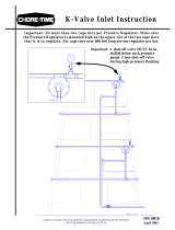
Pressure Regulator Assembly Procedure
Assemble the Inlet Assembly components as shown in the appropriate diagram. Use
PVC Cement (teflon paste on threaded connections) as required.
Figure 15 shows the High Pressure Inlet assembly procedure.
Figure 16 shows the Low Pressure Inlet assembly procedure. For ease of assembly,
build Items 1, 2, 3, & 4 up as one assembly. Build the remaining components up as
another assembly. Finally, glue the two assemblies together.
Motor Location Installation
The Nipple Waterer Line must be cut at each motor location, then restarted after the
motor.
Cut the Nipple Waterer Line near (or just inside) the motor opening. Be sure to
properly debur the end of the pipe to prevent damaging the O-Ring in the Slip
Connector.
Install a Slip Connector on the end of the incoming Nipple Waterer Pipe, as shown in
Figure 14.
Set the outgoing Nipple Waterer Line in it’s appropriate location so that the Nipples
and Locator Blocks are properly positioned.
Note: The Nipple and Locator Blocks should be positioned the same throughout the
system.
Glue a Coupler on the incoming end of the outgoing Nipple Waterer Pipe.
Measure and cut an appropriate length 3/4” pipe to span the motor opening, as
shown in Figure 14. Be sure to properly debur the end of the pipe to prevent
damaging the O-Ring in the Slip Connector.
Glue the 3/4” pipe in the Coupler, as shown in Figure 14, using PVC cement.
Insert the deburred end of the 3/4” pipe in the Slip Connector.
Item Description
1 Incoming Nipple Waterer Line
2 Outgoing Nipple Waterer Line
3 Slip Connector
4 Coupler
5 ULTRAFLO Power Unit
6 Cut a 3/4” pipe to span the motor opening.
Figure 14. Motor Location Installation (front view)

P
a
g
e
1
5
•
C
a
g
e
N
i
p
p
l
e
W
a
t
e
r
i
n
g
I
n
s
t
a
l
l
a
t
i
o
n
M
a
n
u
a
l
Figure 15. 15 - 45 P.S.I Inlet Assembly
Figure 16. 7 - 15 P.S.I. Inlet Assembly
Item Description
1 3/4” PVC Tee (sxsxs)
2* 3/4” x 2” PVC Pipe Nipple
3 3/4” PVC Ball Valve (sxs)
4* 3/4” x 3” PVC Pipe Nipple
5 3/4” PVC Union (sxs)
6 3/4” x 2” PVC Pipe Nipple
7 3/4” PVC Elbow (sxft)
8 Regulator
9 1/2 x 3/4 PVC Adaptor (sxft)
10* 3/4” x 5-1/2” PVC Pipe Nipple
11 Threaded Adapter
12 Washer
13 Indicator Ball
14 Clear Stand Tube
15 1/2” Slip to Garden Hose Adapter
16 Air Remover Cap
17 To Filter Panel
18 To Nipple Waterer Line
*These items must be cut in the field.
Item Description
1 Air Remover Cap
2 1/2” Slip to Garden Hose Adapter
3 Clear Stand Tube - Flexible
4 Stand Tube Support Wire
5 Stand Tube Clamp
6 Regulator
Chore-Time Part
Numbers for the
individual
components are
shown on pages
18 - 21.
Inlet End Installation
Each Pressure Regulator is capable of suppling one tier (two lines) up to 600’ (182.8
m). Systems over 600’ (182.8 m) require two Inlet Assemblies per tier (one per line).
The Inlet Assemblies should be mounted on one side of the cage row in a location that
can be easily reached for adjustment from the aisle and does not interfere with DBS,
egg collectors, etc. Position the Inlet Assemblies in a position to prevent damage.

P
a
g
e
1
6
•
C
a
g
e
N
i
p
p
l
e
W
a
t
e
r
i
n
g
I
n
s
t
a
l
l
a
t
i
o
n
M
a
n
u
a
l
Figure 17. Inlet End Installation on DBS Systems (side view)
Item Description
1 Nipple Pipe Assembly
2 3/4” Coupler
3 3/4” Pipe
4 Pressure Regulator
5 Incoming supply fitting
6 3/4” Nipple
7 3/4” Tee
Dropping Board Scraper Systems: The Inlet Assemblies must be mounted in
a location that does not interfere with the DBS equipment, Egg Collector,
feeding equipment, vent (Turbo Baffle), etc. The installation location shown in
Figure 17 is a suggestion, however, the Inlet Assemblies may be located in a
variety of locations depending on the installation, operation, and location of
other equipment. Additional Elbows and Tees may be required (order separately
as required).
Note:
Make sure the Inlet
Assembly is equal
to or slightly higher
than thenipple
watererline.
Curtain Back Systems: The Inlet Assemblies should be
installed near the end of the cage row. See Figure 18.
When one Regulator is used to supply both lines of a tier, use a
3/4” Nipple and 3/4” Tee to route water to each tier.
Chore-Time Part
Numbers for the
individual
components are
shown on pages
20 - 21.
Item Description
1 Nipple Pipe Assembly
2 3/4” Coupler
3 3/4” Pipe
4 Pressure Regulator
5 Incoming supply fitting
6 3/4” Nipple
7 3/4” Tee
Figure 18. Inlet End Installation on Curtain Back Systems
Top View
Side View

P
a
g
e
1
7
•
C
a
g
e
N
i
p
p
l
e
W
a
t
e
r
i
n
g
I
n
s
t
a
l
l
a
t
i
o
n
M
a
n
u
a
l
Figure 19. Flush End Installation
Qty. Req’d
Item Description 3-Hi 4-Hi
1 1-1/2” Cross 3 4
2 1-1/2” Drain Pipe (10’)
3 1-1/2” x 3/4” Adapter (s x s) 6 8
4 3/4” PVC Pipe 6 8
5 3/4” Street Elbow 6 8
6 3/4” Union 6 8
7 Clear Sight Tube 6 8
8 3/4” Adapter (s x t) 6 8
9 3/4” Elbow (s x t) 6 8
10 1-1/2” PVC Cap 1 1
Common Flush End Installation (preferred drain system)
The flush end components are shipped unassembled.
Figure 19 shows the flush end components assembled on a Curtain-Back Cage
System. The quantity of each individual item required is listed for 3-Hi & 4-Hi
systems.
Dropping Board System flush end components install similarly. However, the flush
end components must be installed outside the End Framing to avoid interference
with D.B.S. equipment. Use a section of 3/4” Pipe to extend the water lines to the
End Framing.
Assemble the components as shown. Use PVC Cement to glue the fittings together.
Drill (4) 1/4” breather holes in the side of the 1-1/2” PVC Cap (near the top of the
cap)
Chore-Time recommends connecting the 1-1/2” drain pipes to a properly sized cross
drain line (1-1/2” minimum). Use an Elbow (not supplied) on one of the outside cage
rows. This will serve as a common drain line to route the flush water to the pit,
lagoon, etc.
Note: Make sure the Stand Tube Assemblies are slightly higher than the Nipple
Waterer Line to aid in air removal.
Chore-Time Part Number for
the individual components
are shown on page 22.

P
a
g
e
1
8
•
C
a
g
e
N
i
p
p
l
e
W
a
t
e
r
i
n
g
I
n
s
t
a
l
l
a
t
i
o
n
M
a
n
u
a
l
Figure 20. Stand Tube Assembly
Qty. Req’d
Item Description 3-Hi 4-Hi
1 Adapter (thread x garden hose) 6 8
2 Shut-Off Valve (thread x thread) 6 8
3 3/4” x 3” Nipple (thread x slip) 6 8
4 Adapter (thread x slip) 6 8
5 Flat Washer 6 8
6 Clear Stand Tube 6 8
7 Indicator Ball 6 8
8 Adapter (thread x slip) 6 8
9 Breather Cap Assembly 6 8
10 3/4” Tee (slip x thread x slip) 6 8
11 Nipple Pipe Assembly -- --
Hose Flush End Installation (alternative drain system)
The flush end components are shipped unassembled.
Figure 20 shows the flush end components assembled on a Curtain-Back Cage
System.
Dropping Board System flush end components install similarly. However, the flush
end components may be installed beyond the End Framing to avoid interference with
D.B.S. equipment. Use a section of 3/4” Pipe to extend the water lines to the End
Framing.
Assemble the components as shown. Use PVC Cement to glue the fittings together.
Apply teflon paste to the threaded components (except item #8).
Chore-Time Part Number for
the individual components
are shown on page 22.

P
a
g
e
1
9
•
C
a
g
e
N
i
p
p
l
e
W
a
t
e
r
i
n
g
I
n
s
t
a
l
l
a
t
i
o
n
M
a
n
u
a
l
This page intentionally left blank.

P
a
g
e
2
0
•
C
a
g
e
N
i
p
p
l
e
W
a
t
e
r
i
n
g
I
n
s
t
a
l
l
a
t
i
o
n
M
a
n
u
a
l
15 - 45 P.S.I. Regulator
Part No. 37147-5
Key Description Part No.
1 Inlet & Body Repair Part - - - -
2 O-Ring - - - -
2 Quad-Ring - - - -
4 Cup Valve - - - -
5 Valve Disc - - - -
6 Regulator Poppet - - - -
7 Compression Spring - - - -
8 Regulator Bulkhead Assembly- - - -
9 #2 Pan Head Screw - - - -
10 Seat - - - -
11 Regulator Lever - - - -
12 Regulator Plate - - - -
13 Compression Spring - - - -
14 Regulator Cap - - - -
15 Regulator Follower - - - -
16 Regulator Knob - - - -
17 Regulator Cover - - - -
18 #6 Pan Head Screw - - - -
19 Compression Spring - - - -
20 Regulator Sleeve - - - -
/