Page is loading ...

RIM-EXIT ELECTRIC STRIKE
10STRIKERE34
10STRIKERE34
©BEA | Original Instructions
75.5012.01 RIM EXIT ELECTRIC STRIKE 20210121 Page 1 of 2
Rim-exit electric strike for access doors
with ½” and ¾” housing thickness
ENGLISH
Shut off all power going to header before attempting any wiring procedures.
Maintain a clean and safe environment when working in public areas.
Constantly be aware of pedestrian traffic around the door area.
Always stop pedestrian traffic through the doorway when performing tests that may result in unexpected reactions by the door.
ESD (electrostatic discharge): Circuit boards are vulnerable to damage by electrostatic discharge. Before handling any board,
ensure you dissipate your body’s ESD charge.
Always check placement of all wiring before powering up to ensure that moving door parts will not catch any wires and cause
damage to equipment.
Ensure compliance with all applicable safety standards (i.e. ANSI A156.10) upon completion of installation.
DO NOT attempt any internal repair of the components. All repairs and/or component replacements must be performed by BEA,
Inc. Unauthorized disassembly or repair:
1. May jeopardize personal safety and may expose one to the risk of electrical shock.
2. May adversely affect the safe and reliable performance of the product resulting in a voided warranty.
½” Strike
(10STRIKEREV12)
¾” Strike
(10STRIKEREV34)
DESCRIPTION
GENERAL SAFETY
UL294 & UL1034 REQUIREMENTS
Visit website for available
languages of this document.
!
CAUTION
Operating voltage 12 or 24 VDC
Current draw 540mA (12 VDC)
270mA (24 VDC)
Operating temperature 14 – 120 °F (-10 – 49 °C)
Humidity 0 – 85% non-condensing
Static strength 1500 lbs (680kg)
Dynamic strength 70 ft-lbs
Endurance 250,000 cycles (UL-tested)
1,000,000 cycles (factory-tested)
Lock mode field selectable fail-safe or fail-secure
Performance level destructive attack: level I
line security: level I
standby power: level I
endurance: level IV
Material (strike body) brushed stainless steel (US32D)
Frame application metal / wood
Latch throw
(housing thickness)
¾” or ½”
Specifications are subject to change without prior notice.
All values measured in specific conditions.
TECHNICAL SPECIFICATIONS
Indoor use only.
Wiring methods shall be in accordance with NFPA70.
10STRIKEREV is intended to be used with UL-listed, rim type, fire exit hardware, Von Duprin LLC, Model 99-F.
10STRIKEREV shall not installed in the fail-secure mode unless permitted by the local Authority Having Jurisdiction (AHJ), and shall not impair panic hardware
operation.
Remove the “Listed Fire Rated Hardware” label if the 10STRIKEREV is used in the fail-safe operation. Using these strikes in fail-safe operation negates the
fire rating. 10STRIKEREV is fire rated in fail-secure operation only.
10STRIKEREV are access control unit accessories intended to be controlled by an access contol system. The purpose of access control systems is to provide a
means for controlling lock and unlocking external and internal doors of a premise.

A
latch position line
inside of
strike keeper
1
5
cable
access
hole
A
2
6
3 4
7 8
Page 2 of 2
MOUNTING & WIRING
Steps 1 – 3 only need to be performed if there was NOT an existing exit device at the installation site.
BEA, Inc., the sensor manufacturer, cannot be held responsible for incorrect installations or incorrect adjustments of the sensor/device; therefore, BEA,
Inc. does not guarantee any use of the sensor/device outside of its intended purpose.
BEA, Inc. strongly recommends that installation and service technicians be AAADM-certifi ed for pedestrian doors, IDA-certifi ed for doors/gates, and
factory-trained for the type of door/gate system.
Installers and service personnel are responsible for executing a risk assessment following each installation/service performed, ensuring that the sensor/
device system installation is compliant with local, national, and international regulations, codes, and standards.
Once installation or service work is complete, a safety inspection of the door/gate shall be performed per the door/gate manufacturer’s recommendations
and/or per AAADM/ANSI/DASMA guidelines (where applicable) for best industry practices. Safety inspections must be performed during each service
call – examples of these safety inspections can be found on an AAADM safety information label (e.g. ANSI/DASMA 102, ANSI/DASMA 107).
Verify that all appropriate industry signage and warning labels are in place.
BEA, INC. INSTALLATION/SERVICE COMPLIANCE EXPECTATIONS
T
ech Support & Customer Service: 1-800-523-2462 | General Tech Questions: [email protected] | Tech Docs: www.BEAsensors.com
©BEA | Original Instructions
75.5012.01 RIM EXIT ELECTRIC STRIKE 20210121
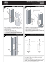
Measure 39
13
⁄16” (1011mm) from
the finished floor and mark strike
centerline on the door. Transfer
centerline to frame.
Close the door and mark the latch
position on the frame. The latch
position line will correspond with
the inside of the strike keeper as
shown.
Align the strike on the centerline
and mark two slotted holes. Drill
holes and secure strike to frame.
Position the strike on the frame
according to the marks. Using the
strike as a template, mark and
drill a cable access hole and two
mounting holes. Loosely mount the
strike with Phillips flathead screws.
Align template on centerline and
against strike.
Measure the exit device latch
position on the door.
Check latchbolt interaction and
adjust the strike horizontally until
the door latches properly, then
tighten the two mounting screws
and mark remaining screw holes.
Remove the strike and drill marked holes.
Wire accordingly. Insert the blind nuts
into the holes and re-install the strike. If
necessary, add spacers to adjust the gap
between the strike and exit device. Secure
the strike with the hex-socket, cap screws
into the blind nuts.
Connection Diagram
Fail-safe / Fail-secure Reversible
12 VDC
white
control device
black
(not polarity sensitive)
24VDC
control device
(not polarity sensitive)
red
black
12 VDC operation
24 VDC operation
Remove locking screw, loosen, slide and tighten sliding screw.
Reinsert and tighten locking screw to the desired fail-safe or
fail-secure setting.
Fail-Safe: screws locked AWAY from each other
Fail-Secure: screws locked TOWARDS each other
locking screw
locking screw
sliding screw
sliding screw
/