Page is loading ...

42.5
04
1
4
4
7
5
2
.
29
5.74
52
.0
4
2
5
2
662
082
1
2
35
3
25
14
2.1. 3. 4.
Measure latch position.
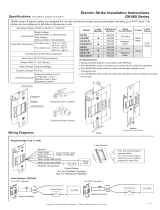
Monitoring Output: Lock status
Current Draw: 280mA/12VDC, 140mA/24VDC
Operating Temperature: -10~+45ºC
Operating Voltage: 12 or 24VDC
Mark latch position on the frame.
GK236M Series Electric Strike Installation Instructions
(For Wood Doors)
Humidity: 0~95% non-condensing
+
+
+
+
+
+
_
NO.
COM.
NC.
+
-
Lock Status Output
N.C. contact output: unlocked status
N.O. contact output: locked status
Power
Input
Control Device
(e.g. Reader)
Drill and cut the frame. Connect the wires and install the
strike.
Lock Mode: Fail-safe
Latch Throw: 11mm
Keeper Width: 48mm
Solenoid Testing: Over 250,000 cycles
Unit: mm
Static Stength: 1500 lbs.
Preload: Up to 500 lbs.
Net Weight: 645g
Installation Steps
Specifications
Handing Guide
Keeper Adjustment
Construction: Stainless steel
Copyright © All rights reserved. P-MU-GK236M Published on 2017.09.18
The strike keeper can be adjusted horizontally to account for various installation
anomalies. To adjust the keeper, loosen the adjustment screws, move the keeper
horizontally as needed, and retighten the adjustment screws.
(Maximum adjustable range: 3mm)
Adjustment
Screws
Strike
Keeper
Strike
Keeper
Adjustment
Screws
Door handing is determined from the side of the door where
the hinges are visible, according to the German standard DIN
107.
Stand facing the door on the hinge / pull side. If the hinge is on the
right, the door is considered to be DIN right. If the hinge is on the
left, then the door is considered to be DIN left.
DIN left DIN right
DIN left DIN right
Chisel
Models
DIN left DIN right
GK236M-L-PL-12 GK236M-R-PL-12
GK236M-L-PL-24 GK236M-R-PL-24
/