
The GK1276/1296 series electric rim strikes are
surface mounted and designed to accommodate rim
exit devices with a Pullman latch. No cutting on the
frame is required for installation. These strikes are
field selectable for fail-safe or fail-secure mode and
operate on dual voltage 12/24 VDC. Available with
optional latch monitor.
Surface Installation
• For indoor use only
• The GK1276/1296 series are intended to be used with UL Listed
Exit Hardware.
• The GK1276/1296 series shall not impair the operation of panic
hardware mounted on the door.
UL Requirements
GK1276/1296 Series Electric Rim Strikes
Installation Instructions
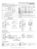
Specifications
Operating Voltage
Current Draw
Operating Temperature
Humidity
12/24VDC
0~85% non-condensing
540mA/12VDC, 270mA/24VDC
Static Strength
Lock Mode
Field selectable fail-safe
or fail-secure
1500 lbs (680Kg)
Dynamic Strength 70 ft-lbs
Endurance Rating
250,000 cycles (UL tested)
1,000,000 cycles (Factory tested)
14
°F to 120°F (-10°C~+49°C)
Model
GK1276
GK1276M
Performance Level
Destructive Attack: Level I
Line Security: Level I
Standby Power: Level I
Endurance: Level IV
Finish Brushed stainless steel (US32D)
• The GK1276/1296 series electric strikes are access control unit
accessories, intended to be controlled by an access control system. The
access control systems purpose is to provide a means for controlling the
locking and unlocking of external and internal doors of a premise.
Copyright © All rights reserved. P-MU-GK1276 Published on 2020.02.27
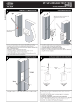
Measure 39 13/16”
(1011mm) up from
finished floor and mark
strike centerline on
door. Transfer
centerline to frame.
39
13
16
“
(1011mm)
1
2
3
Surface Installation (For Exit Device Already Installed)
Model GK1296 is used as example below.
Align strike on
centerline and mark
two slotted holes.
Drill holes and install
strike to frame.
Align template on
centerline and
against strike.
A
1
Cable
Access
Hole
3
2
A
4
5
Latch Position Line
a. Close the door and mark latch
position on the frame.
b. The latch position line will
correspond with the inside of strike
keeper as shown.
a. Position the strike on the frame
according to the marked latch
position.
b. Use the strike as a template; mark
and drill cable access hole and two
mounting holes.
c. Loosely mount the strike with
Phillips flat head screws.
a. Check latchbolt interaction and
adjust the strike horizontally until the
door latches properly.
b. Tighten the two mounting screws
and mark remaining screw holes.
Inside of
Strike Keeper
a. Remove the strike and drill holes.
b. Connect the wires.
c. Insert the blind nuts into the holes
and re-install the strike.
d. Add spacers to adjust the gap
between strike and exit device if
necessary.
e. Permanently secure the strike with
the hex socket cap screws into the
blind nuts.
a. Measure the exit device latch
position on the door.
GK1296
GK1296M
Frame Application Metal or Wood
Latch Throw
(Housing Thickness)
3/4" 1/2"
• Wiring methods shall be in accordance with NFPA 70.

Place the wire inside the connector and use pliers to press down on
the head of the connector evenly.
Latch Monitor (Option)
Contact Rating
Blue N.O.
Green COM.
Yellow N.C.
Wiring Diagrams
Control Device
Red
Black
Control Device
White
Black
(Polarity Insensitive)
(Polarity Insensitive)
Remove locking screw #1, loosen, slide and tighten sliding screw #2. Reinsert and tighten locking screw #1 to the desired fail-safe or fail-secure
setting.
Fail-Safe Fail-Secure
For 12VDC operation:
For 24VDC operation:
Copyright © All rights reserved. P-MU-GK1276 Published on 2020.02.27
Dimensions
Installing the Crimp Connectors
GK1276M: 1.5A/40VDC
GK1296M: 0.3A/6VDC
N.C. contact
for door closed
status
Changing Fail-Safe / Fail-Secure
GK1276
GK1296
Fail-Secure
Fail-Safe
GK1276 GK1276M GK1296(3) GK1296M(3)
8 1/4” (209.5mm)
6 7/16” (163mm)
1/8” (3.5mm)
(Model with Latch Monitor)
(Model with Latch Monitor)
N.O. contact for
door open status
Locking screw #1
Locking screw #1
Sliding screw #2
Sliding screw #2
9” (228.5mm)
1 1/2” (38.5mm)
(19mm)
3/4”
(44.5mm)
1 3/4”
9” (228.5mm)
1 1/2” (38.5mm)
(19mm)
3/4”
(44.5mm)
1 3/4”
(13mm)
1/2”
(44.5mm)
1
3/4”
(13mm)
1/2”
(44.5mm)
1
3/4”
9” (228.5mm)
1 1/2” (38.5mm)
9” (228.5mm)
1 1/2” (38.5mm)
GK1296M(2)GK1296(2)
9” (228.5mm)
9” (228.5mm)
1 1/2” (38.5mm)
(13mm)
1/2”
(44.5mm)
1
3/4”
(13mm)
1/2”
1 1/2” (38.5mm)
(44.5mm)
1
3/4”
-
 1
1
-
 2
2


Gianni Industries GK1276 Installation guide
- Type
- Installation guide
- This manual is also suitable for
Ask a question and I''ll find the answer in the document
Finding information in a document is now easier with AI
Related papers
-
Gianni Industries GK1297 Installation guide
-
-
-
Gianni Industries GML800 Installation guide
-
-
Gianni Industries GK1900 Installation guide
-
 Gianni GK460 Series Installation guide
-
Gianni Industries GK850/GK851 Installation guide
-
-

Other documents
-
Cal-Royal ES1433 Grade 1 Universal Electric Strike User manual
-
Cal-Royal ES1520 Grade 1 No-Cut Electric Strike User manual
-
 Lockwood ES150 Series Installation guide
-
Von Duprin 6300 Installation guide
-
 FSH FES15M Technical Manual
-
Cal-Royal CAL-ROYAL ES1140 Electric Strike and Accessories User manual
-
-
BEA ELECTRIC STRIKES User guide
-
SECO-LARM SD-998C-D3AQ Owner's manual
-
SECO-LARM SD-998C-NUAQ Owner's manual

