Page is loading ...

CYLINDRICAL UNIVERSAL ELECTRIC STRIKE
©BEA | Original Instructions
75.5011.01 CYLINDRICAL UNIVERSAL ELECTRIC STRIKE 20201110 Page 1 of 2
Cylindrical electric strike for access doors
ENGLISH
Shut off all power going to header before attempting any wiring procedures.
Maintain a clean and safe environment when working in public areas.
Constantly be aware of pedestrian traffic around the door area.
Always stop pedestrian traffic through the doorway when performing tests that may result in unexpected reactions by the door.
ESD (electrostatic discharge): Circuit boards are vulnerable to damage by electrostatic discharge. Before handling any board,
ensure you dissipate your body’s ESD charge.
Always check placement of all wiring before powering up to ensure that moving door parts will not catch any wires and cause
damage to equipment.
Ensure compliance with all applicable safety standards (i.e. ANSI A156.10) upon completion of installation.
DO NOT attempt any internal repair of the components. All repairs and/or component replacements must be performed by BEA,
Inc. Unauthorized disassembly or repair:
1. May jeopardize personal safety and may expose one to the risk of electrical shock.
2. May adversely affect the safe and reliable performance of the product resulting in a voided warranty.
Only one bracket included.
5”5” 8”
DESCRIPTION
GENERAL SAFETY
UL294 & UL1034 REQUIREMENTS
Visit website for available
languages of this document.
!
CAUTION
Operating voltage 12 or 24 VDC
Current draw 300mA (12 VDC)
150mA (24 VDC)
Operating temperature 32 – 120 °F (0 – 49 °C)
Humidity 0 – 85% non-condensing
Latch throw
9
⁄16” (15mm) max.
Keeper width 1
6
⁄17” (36mm)
Static strength 1000 lbs (454kg)
Dynamic strength 50 ft-lbs
Endurance 250,000 cycles (UL-tested)
1,000,000 cycles (factory-tested)
Material (strike body) zinc alloy / stainless steel
Specifications are subject to change without prior notice.
All values measured in specific conditions.
TECHNICAL SPECIFICATIONS
Indoor use only.
Wiring methods shall be in accordance with NFPA70.
10STRIKECUV is intended to be used with UL-listed exit hardware.
10STRIKECUV shall not impair the intended operation of an emergency exit.
10STRIKECUV shall not impair the operation of panic hardware mounted on the door.
The CYLINDRICAL UNIVERSAL ELECTRIC STRIKES are designed to accommodate either cylindrical or mortise locksets
up to 9/16” (15mm) throw latchbolt. When installed with a fail secure manner, the local authority shall be consulted
with regard to the use of possible panic hardware to allow emergency exit from the secured area.

step 1
step 4
1
4
step 2
step 5
step 3
step 6
2
5
3
6
©BEA | Original Instructions
75.5011.01 CYLINDRICAL UNIVERSAL ELECTRIC STRIKE 20201110 Page 2 of 2
MOUNTING & WIRING
Measure latch position.
Proper gap must be reserved between the strike keeper and latch bolt to prevent failure of solenoid valve.
Cut hole using template.
Mark latch position line.
Install mounting tabs.
Attach sticker template to
marked centerline.
Connect wires using crimp
connections. Test strike, ensuring
it is receiving correct voltage.
BEA, Inc., the sensor manufacturer, cannot be held responsible for incorrect installations or incorrect adjustments of the sensor/device; therefore, BEA,
Inc. does not guarantee any use of the sensor/device outside of its intended purpose.
BEA, Inc. strongly recommends that installation and service technicians be AAADM-certifi ed for pedestrian doors, IDA-certifi ed for doors/gates, and
factory-trained for the type of door/gate system.
Installers and service personnel are responsible for executing a risk assessment following each installation/service performed, ensuring that the sensor/
device system installation is compliant with local, national, and international regulations, codes, and standards.
Once installation or service work is complete, a safety inspection of the door/gate shall be performed per the door/gate manufacturer’s recommendations
and/or per AAADM/ANSI/DASMA guidelines (where applicable) for best industry practices. Safety inspections must be performed during each service
call – examples of these safety inspections can be found on an AAADM safety information label (e.g. ANSI/DASMA 102, ANSI/DASMA 107).
Verify that all appropriate industry signage and warning labels are in place.
BEA, INC. INSTALLATION/SERVICE COMPLIANCE EXPECTATIONS
Tech Support & Customer Service: 1-800-523-2462 | General Tech Questions: [email protected] | Tech Docs: www.BEAsensors.com
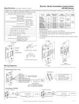
Connection Diagram
Fail-safe / Fail-secure Reversible
12 VDC
control device
(not polarity sensitive)
white
black
24VDC
control device
(not polarity sensitive)
red
black
12 VDC operation
Fail-safe and fail-secure are changeable by moving
the position of the locking screws.
24 VDC operation
Fail-Secure
(power to open)
Fail-Safe
(power to lock)
/