Page is loading ...

© Copyright 2017 WyreStorm Technologies | WyreStorm.com
North America: 844.280.WYRE (9973) | UK/EMEA: +44 (0) 1793 230 343
Email: Support@WyreStorm.com
Presentation Switcher
SW-0402-MV-HDMI | SW-0402-MV-HDBT
Installation Guide
Document Revision:
v1.1
Document Date:
February 3
rd
2017
Supported Firmware:
All Versions

© Copyright 2017 WyreStorm Technologies | WyreStorm.com
SW-0402-MV-HDxx Installation Guide | 170404-1529
2 of 26
North America: 844.280.WYRE (9973) | UK/EMEA: +44 (0) 1793 230 343
Email: Support@WyreStorm.com
IMPORTANT! Safety Information
Safety Classifications
Note:
Provides special information for installing, configuring, and operating the
equipment.
IMPORTANT!
Provides special information that is critical to installing, configuring, and
operating the equipment.
CAUTION!
Provides special information on avoiding situations that may cause damage to
equipment.
WARNING!
Provides special information on avoiding situations that may cause physical
danger to the installer, end user, etc.
ELECTRIC SHOCK!
The source power poses an electric shock hazard that has the potential to
cause serious injury to installers and end users.
ELECTRICAL DISCONNECT:
The source power outlet and power supply input power sockets should be
easily accessible to disconnect power in the event of an electrical hazard or
malfunction.
WEIGHT INJURY!
Installing some of the equipment requires two installers to ensure safe handling
during installation. Failure to use two installers may result in injury.
Safety Statements
1. Read these instructions in their entirety and retain a copy for later reference.
2. Follow all instructions and heed all warnings.
3. Do not expose this apparatus to rain, moisture, sprays, drips or splashes and ensure that no objects containing liquids are placed on the
apparatus, including cups, glasses and vases.
4. Do not place this unit in a confined space such as enclosed shelving, cabinets or bookshelves. Ensure the unit is adequately ventilated.
5. To prevent the risk of electric shock or fire hazard due to overheating, do not cover the unit or obstruct ventilation openings with material,
newspaper, cardboard or anything that may restrict airflow into the unit.
6. Do not install near external heat sources such as radiators, heat registers, boilers or any device that produces heat such as amplifiers or
computers and do not place near sources of naked flame.
7. Unplug apparatus from power supply during lightning storms or when unused for long periods of time.
8. Protect the power cable from being walked on, pinched or restricted in any way, especially at plug connections.
9. Only use attachments/accessories specified by the manufacturer.
10. Units contain non-serviceable parts - Refer all servicing to qualified service personnel.
IMPORTANT!
Do Not Hot swap HDMI or HDBaseT connections - Please insert and extract cables carefully with the power SWITCHED OFF. Power
is passed along transmissions so connecting and disconnecting cables while powered can result in damage to circuitry or possible
injury.

© Copyright 2017 WyreStorm Technologies | WyreStorm.com
SW-0402-MV-HDxx Installation Guide | 170404-1529
3 of 26
North America: 844.280.WYRE (9973) | UK/EMEA: +44 (0) 1793 230 343
Email: Support@WyreStorm.com
Contents
IMPORTANT! Safety Information ........................................................................................................................................................................ 2
1. Overview ....................................................................................................................................................................................................... 4
1.1 Before Beginning ................................................................................................................................................................................................... 4
2. Product Overview ......................................................................................................................................................................................... 5
2.1 Key Features .......................................................................................................................................................................................................... 5
2.2 In the Box ................................................................................................................................................................................................................ 5
2.3 Front Panel ............................................................................................................................................................................................................. 5
2.4 Rear Panel............................................................................................................................................................................................................... 6
2.5 Specifications......................................................................................................................................................................................................... 7
2.6 Dimensions ............................................................................................................................................................................................................. 8
2.7 Typical Application ................................................................................................................................................................................................ 8
3. Installation .................................................................................................................................................................................................. 10
3.1 Shelf Placement ................................................................................................................................................................................................... 10
3.2 Rack Placement ................................................................................................................................................................................................... 10
4. Wiring and Connections ............................................................................................................................................................................. 10
4.1 HDMI/HDBaseT Wiring ....................................................................................................................................................................................... 10
4.2 Video and Audio Wiring ...................................................................................................................................................................................... 11
4.3 IR Wiring ................................................................................................................................................................................................................ 11
4.4 RS-232 Wiring ...................................................................................................................................................................................................... 11
5. Display Modes ............................................................................................................................................................................................ 13
5.1 Multi-View (MV)/Picture in Picture (PIP) Mode .............................................................................................................................................. 13
PIP Window Order ............................................................................................................................................................................................... 13
5.2 Quad-View Mode ................................................................................................................................................................................................. 13
5.3 4x2 Matrix Mode .................................................................................................................................................................................................. 13
6. Controlling the SW-0402-MV-HDxx ............................................................................................................................................................ 14
6.1 Front Panel Control ............................................................................................................................................................................................. 14
6.2 Handheld Remote Operation ............................................................................................................................................................................. 14
7. Using SW-0402 Console ............................................................................................................................................................................ 15
7.1 Management Suite Installation ......................................................................................................................................................................... 15
7.2 Connecting to a PC ............................................................................................................................................................................................. 15
7.3 Configuring the PCs COM Port .......................................................................................................................................................................... 15
7.4 Establishing Communication with the Scaler ................................................................................................................................................. 16
7.5 Configuring EDIDs ............................................................................................................................................................................................... 16
7.6 Selecting a Source ............................................................................................................................................................................................... 18
7.7 Controlling Multi-View in the PC Console ........................................................................................................................................................ 19
7.8 HDMV Settings Tab Overview ........................................................................................................................................................................... 20
7.9 Preset Tab Overview ........................................................................................................................................................................................... 21
7.10 Configuring the Network Connection ............................................................................................................................................................... 21
8. Troubleshooting ......................................................................................................................................................................................... 23
Contacting Technical Support ................................................................................................................................................................................... 23
9. Revision History ......................................................................................................................................................................................... 23
Publication Disclaimer ....................................................................................................................................................................................... 25

© Copyright 2017 WyreStorm Technologies | WyreStorm.com
SW-0402-MV-HDxx Installation Guide | 170404-1529
4 of 26
North America: 844.280.WYRE (9973) | UK/EMEA: +44 (0) 1793 230 343
Email: Support@WyreStorm.com
1. Overview
This Installation Guide will guide the installer through the process of installing and configuring a WyreStorm SW-0402-MV-HDMI or
SW-0402-MV-HDBT Multi-View Scaler. Print out this page to use as a checklist for items required to install this WyreStorm device.
WyreStorm recommends reading through this document in its entirety to become familiar with the product’s features prior to
starting the installation process.
1.1 Before Beginning
WyreStorm recommends visiting the product page before installing this product for updates to this Quickstart Guide as well as other
information about this product.
Read through this document in its entirety. ........................................................................................................................................
SW-0402-MV-HDMI or SW-0402-MV-HDBT Multi-View Scaler ........................................................................................................
Required cables and connectors to connect sources and displays. ...............................................................................................
See Wiring and Connections for details on connector types and wiring guidelines.
Sources and displays to be used in the system .................................................................................................................................
IR receiver to extend the IR sensor for control of the Multiview Scaler. .........................................................................................
Ethernet network components and network usernames and passwords (if applicable) ............................................................
Management Suite Configuration Tool downloaded from WyreStorm.com. ................................................................................

© Copyright 2017 WyreStorm Technologies | WyreStorm.com
SW-0402-MV-HDxx Installation Guide | 170404-1529
5 of 26
North America: 844.280.WYRE (9973) | UK/EMEA: +44 (0) 1793 230 343
Email: Support@WyreStorm.com
2. Product Overview
The WyreStorm SW-0402-MV-HDMI is a 4-input to 2-output scaling device that allows both analog and/or digital AV sources to be
connected. Each of the four source input locations have three connection options: HDMI, VGA or YUV. Additionally, each analog input
includes an audio input (stereo mini for VGA and RCA L/R for YUV) for embedding the video with an external audio source.
2.1 Key Features
Both outputs have coaxial S/PDIF connections to allow audio signals from any of the four inputs to be sent to an audio
amplifier.
Advanced image processor controls source opacity and image border.
Scale and arrange images on the screen in real-time using the API or supplied software package.
Advanced EDID functionality allows the unit to store and recall settings previously identified.
The SW-0402-MV-HDMI scales input from any of the sources from 480i to 1080p.
Each input allows for separate embedded audio via a line in stereo mini connection.
The product comes with a built-in Web UI for advanced settings via a tablet or computer.
Audio output with variable delay for AV sync.
Control with LAN, RS-232 and IR functionality.
2.2 In the Box
1x SW-0402-MV-HDMI or SW-0402-MV-HDBT Multi-View Scaler
1x 12V DC 3A Power Supply (US/UK/EU)
1x Handheld IR Remote
1x IR Receiver Extension Cable
2x Mounting Brackets
1x Quickstart Guide
2.3 Front Panel
IR Sensor
38kHz IR Receiver.
Receives an IR signal from the included handheld remote or emitter for source selection and other
switcher functions.
Input 1-4
Selection
Selects the numbered input to assign to an output.
Source Selection
Selects the source for the currently selected input number.
Example: HDMI 1, VGA 2, etc.
MV Mode
Selects the MV mode for the currently selected source.
2K QV/4K QV
Selected 2K or 4K output for the currently selected source.
LCD Display
Displays current source selection and source type for each output.

© Copyright 2017 WyreStorm Technologies | WyreStorm.com
SW-0402-MV-HDxx Installation Guide | 170404-1529
6 of 26
North America: 844.280.WYRE (9973) | UK/EMEA: +44 (0) 1793 230 343
Email: Support@WyreStorm.com
2.4 Rear Panel
LAN
8-pin RJ-45 female | 10/100 Mbps auto-negotiating:
Connect to a Local Area Network for accessing the built-in Web UI.
RS-232 In/Loop
RS-232 Loop: 9-pin DB9 Male | RS-232 In: 9-pin DB9 Female
Connect to a control system to control the switcher and loop to other switchers.
See RS-232 Wiring for connector pinouts.
YUV/ CVBS
(Component/
Composite Video)
RCA Female(3x):
Connect YUV to the component video output of a source device.
Connect CVBS (YUV Green) to the composite video output of a source device.
See YUV/CVBS (Component/Composite Video) Wiring for connector pinouts.
Audio In
(YUV/CVBS Audio)
RCA Female (2x): Connect to the analog audio output of the source connected to the CVBS input. See Audio In-S/PDIF
Out Wiring for connector pinouts.
S/PDIF Out
RCA Female (Digital Coax)
Outputs a digital S/PDIF audio signal to the display or amplifier with a digital coax input.
See Audio In-S/PDIF Out Wiring for connector pinouts.
IR Ext
3.5mm (1/8in) Stereo Plug: Connect to an IR receiver (not included) when the switcher is placed in a cabinet or out of
range of the IR remote.
See IR Wiring for connector pinouts.
HDMI In
19-pin type A HDMI female digital video/audio: Supports HDMI and DVI/D (requires adapter-not included). See
HDMI/HDBaseT Wiring for important wiring guidelines.
Line In
(VGA Audio)
3.5mm (1/8in) Stereo Plug
Connect to the analog audio output of the source connected to the VGA input.
See Line In Wiring for connector pinouts.
VGA In
15-pin VGA VESA (D-SUB 15):
Connect to D-SUB 15 VGA output of a device such as a computer.
15-pin VGA cable is required.
Video Outputs
SW-0402-MV-HDMI: 2x HDMI Out19-pin type A HDMI female digital video/audio
SW-0402-MV-HDBT: 1x HDMI Out19-pin type A HDMI female digital video/audio | 1x HDBT Out 8-pin RJ-45 female
Power In
5.5mm Male Barrel Jack
Connect to the included 12V DC 3A power supply.

© Copyright 2017 WyreStorm Technologies | WyreStorm.com
SW-0402-MV-HDxx Installation Guide | 170404-1529
7 of 26
North America: 844.280.WYRE (9973) | UK/EMEA: +44 (0) 1793 230 343
Email: Support@WyreStorm.com
2.5 Specifications
Audio and Video
Inputs
4x HDMI In 19-pin HDMI type A female | 4x VGA In 15-pin DSUB15 VGA
4x YUV IN YUV RCA Female(s) | 4x CVBS (Composite In) RCA Female (YUV Green)
4x Line In 3.5mm (1/8in) Stereo Jack | 4x Audio In L&R RCA Female
Outputs
HDMI Version:
2x HDMI Out 19-pin HDMI type A female | 2x S/PDIF Out RCA Female Digital
HDBT Version:
1x HDMI Out 19-pin HDMI type A female | 1x HDBT Out 8-pin RJ-45 female | 2x S/PDIF Out RCA Female Digital
Audio Formats
2ch PCM
Video Resolutions (Max)
HDMI
1920x1080p @60Hz 12bit (15m/50ft) | 16bit (7m/23ft)
3840x2160p @30Hz 4:4:4 8bit (7m/23ft) | @24Hz 4:2:0 HDR 10bit (3m/9.8ft)
Cat6 (HDBT Version)
1920x1080 @60Hz 12bit (100m/328ft) | @60Hz 16bit (70m/230ft)
3840x2160p @30Hz 4:4:4 8bit (70m/230ft) | @24Hz 4:2:0 HDR 10bit (70m/230ft)
Cat6a/7 (HDBT Version)
1920x1080 @60Hz 12bit (100m/328ft)
3840x2160p @30Hz 4:4:4 8bit (100m/328ft) | @24Hz 4:2:0 HDR 10bit (100m/328ft)
Color Depth
1080p: 16bit | 4K UHD: 8bit | HDR @24p: 10bit BT.2020
Maximum Pixel Clock
HDMI: 600mHz | HDBaseT: 297MHz
Communication and Control
HDMI
HDCP 2.2 compliant | EDID | DVI/D supported with adapter (not included)
HDBaseT
HDCP 2.2 compliant | EDID | ARC | 1-way PoH | Bidirectional IR and Ethernet
Ethernet
1x 8-pin RJ-45 female | Web UI | IP Control | Bidirectional over HDBaseT
IR
1x IR Ext - 3.5mm (1/8in) Stereo | Matrix Control
6x IR TX - 3.5mm (1/8in) Mono | Bidirectional over HDBaseT
6x IR RX - 3.5mm (1/8in) Stereo | Bidirectional over HDBaseT
RS-232
Matrix Control | Firmware Updates
Audio Return Channel (ARC)
Returns audio to source location from remote display via HDBaseT | Outputs 5-6 only
Power
Power Supply
Input: 100~240V AC 50/60Hz
PoH
48V 15.4W
Max Power Consumption
88.6W
Environmental
Operating Temperature
32°F ~ 113°F (0°C ~ 45°C)
10% ~ 90%, non-condensing
Storage Temperature
-4°F to ~ 158°F (-20°C ~ +70°C)
10% ~ 90%, non-condensing
Maximum BTU
302.3 BTU/hr
Dimensions and Weight
Rack Units/Wall Box
3U
Height
100mm/3.94in
Width
440mm/17.33in
Depth
340mm/13.39in
Weight
8.2kg/18.04lbs
Regulatory
Safety and Emission
CE | FCC

© Copyright 2017 WyreStorm Technologies | WyreStorm.com
SW-0402-MV-HDxx Installation Guide | 170404-1529
8 of 26
North America: 844.280.WYRE (9973) | UK/EMEA: +44 (0) 1793 230 343
Email: Support@WyreStorm.com
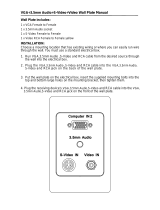
2.6 Dimensions
2.7 Typical Application
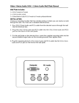
A typical application for the SW-0402- Multi-View scaler contains the following components. While other items can be added to the
configuration, the items listed below are the devices typically found in the average installation of this product.
Multi-View scaler
Blu-ray player
Cable/Satellite Box(es)
Media Players
Laptop or Desktop Computers
Security Cameras
Local Area Network (LAN) components
IR, RS-232, or IP Control System

© Copyright 2017 WyreStorm Technologies | WyreStorm.com
SW-0402-MV-HDxx Installation Guide | 170404-1529
9 of 26
North America: 844.280.WYRE (9973) | UK/EMEA: +44 (0) 1793 230 343
Email: Support@WyreStorm.com
Basic Wiring Diagram

© Copyright 2017 WyreStorm Technologies | WyreStorm.com
SW-0402-MV-HDxx Installation Guide | 170404-1529
10 of 26
North America: 844.280.WYRE (9973) | UK/EMEA: +44 (0) 1793 230 343
Email: Support@WyreStorm.com
3. Installation
3.1 Shelf Placement
This product should be installed on a solid, flat, level surface such as a table, cabinet or shelf using the four included feet. The
location should be dry, well ventilated, and out of direct sunlight.
It is acceptable to stack multiple products one atop of the other without a ventilation space between the units. However, WyreStorm
recommends that if using more than two of this product, an empty space at least 1 rack unit (1.75 in) in height is used between every
2 chassis. This will assist in heat dissipation and prevent thermal protection from activating due to overheating.
3.2 Rack Placement
Rack ears (mounting brackets) are included with this product for installation in a standard 19-inch equipment rack. When installing in
a rack, the attached feet located on the bottom of the chassis must be removed.
4. Wiring and Connections
WyreStorm recommends that all wiring for the installation is run and terminated prior to making connections to the switcher. Read
through this section in this entirety before running or terminating the wires to ensure proper operation and to avoid damaging
equipment.
4.1 HDMI/HDBaseT Wiring
IMPORTANT! HDMI/HDBaseT Wiring Guidelines
The use of patch panels, wall plates, cable extenders,
kinks in cables, and electrical or environmental
interference will have an adverse effect on HDMI and
Ethernet transmission limiting performance. Steps
should be taken to minimize or remove these factors
completely during installation for best results.
While similar in nature, the HDBaseT protocol is
different than Ethernet and voltages provided for PoH
can be higher than those provided by PoE. For this
reason, never connect an HDBaseT link to an Ethernet
router or switch to avoid damaging the connected
devices.
WyreStorm recommends using high quality HDMI
cables such as WyreStorm Express to ensure the
highest content performance available.
The type of category cable used and length can restrict
the available video resolution. While Cat5e can be used,
WyreStorm recommends using Cat6 or higher to
ensure the highest content performance available. See
Video Resolutions in the Specifications table before
determining cable type and length.
HDBaseT Wiring (follows the EIA T568B standard)

© Copyright 2017 WyreStorm Technologies | WyreStorm.com
SW-0402-MV-HDxx Installation Guide | 170404-1529
11 of 26
North America: 844.280.WYRE (9973) | UK/EMEA: +44 (0) 1793 230 343
Email: Support@WyreStorm.com
4.2 Video and Audio Wiring
YUV/CVBS (Component/Composite Video) Wiring
Connection for YUV/CVBS inputs use an RCA Male connector
for each of the individual connections.
Audio In-S/PDIF Out Wiring
Connection for Audio In uses an RCA Male connector for the
left and the right inputs.
Line In Wiring
Connection for Line In uses a 3.5mm (1/8in) stereo
connector.
4.3 IR Wiring
Connection for IR RX (receive) uses a 3.5mm (1/8in) stereo jack that outputs +5V DC to power the included IR receiver.
IMPORTANT! IR TX Connection Guidelines
3rd party IR receivers may require a different voltage,
refer to the documentation provided with the IR
receiver before making any connections to avoid
damaging the device.
When connecting to an IR control system use the
WyreStorm CAB-IR-LINK cable to remove the sleeve
+5V DC.
Visit the CAB-IR-LINK product page for details.
4.4 RS-232 Wiring
The following wiring diagram shows the pinouts for the switcher. While not shown, connect the TX (transmit) to RX (receive) pin at
the control system or PC side of the cable. Most control systems and computers are DTE where pin 2 is RX, this can vary from
device to device. Refer to the documentation for the connected device for pin functionally to ensure that the correct connections can
be made.
Additionally, the switcher contains a RS-232 loop out to control additional Multi View Scalers. This is a male DB9 port with DTE
configuration. Use a straight-through cable when connecting from one switcher to another. Refer to the SW-0402-MV-HDxx RS-232
Commands document located on the product page for RS-232 control commands.

© Copyright 2017 WyreStorm Technologies | WyreStorm.com
SW-0402-MV-HDxx Installation Guide | 170404-1529
12 of 26
North America: 844.280.WYRE (9973) | UK/EMEA: +44 (0) 1793 230 343
Email: Support@WyreStorm.com
RS-232 In Port DCE Pinout
1x 9-pin DB9 Female
RS-232 Loop Port DTE Pinout
1x 9-pin DB9 Male
RS-232 Loop Connections

© Copyright 2017 WyreStorm Technologies | WyreStorm.com
SW-0402-MV-HDxx Installation Guide | 170404-1529
13 of 26
North America: 844.280.WYRE (9973) | UK/EMEA: +44 (0) 1793 230 343
Email: Support@WyreStorm.com
5. Display Modes
5.1 Multi-View (MV)/Picture in Picture (PIP) Mode
When a Multi-View mode is selected, the screen will display a main source and three other sources in smaller PIP windows. While the
layouts can be customized, there are 4 presets that correlate to the front panel and handheld remote buttons. The output to each
display is mirrored during MV mode displaying the same content on both displays.
MV-A
MV-B
MV-C
MV-D
PIP Window Order
While the graphics above show the main image as input 1, this will change based on the selected input. The main image will change
to the input number and image 1 will move to the first PIP window.
Selected Input
PIP Window Order
Input 1
Main= Input 1, PIP2= Input 2, PIP3= Input 3, PIP4=
Input 4
Input 2
Main= Input 2, PIP2= Input 1, PIP3= Input 3, PIP4=
Input 4
Input 3
Main= Input 3, PIP2= Input 1, PIP3= Input 2 PIP4=
Input 4
Input 4
Main= Input 4, PIP2= Input 1, PIP3= Input 2, PIP4=
Input 3
5.2 Quad-View Mode
When a Quad-View mode is selected, the screen will display the sources in 4 quadrants on the screen. As with Multi-View, there are 4
presets that correlate to the front panel and handheld remote buttons. The output to each display is independent during MV mode
allowing for different content on each display.
2K/4K QV
5.3 4x2 Matrix Mode
This mode allows for a single image to appear on the display from a single source.

© Copyright 2017 WyreStorm Technologies | WyreStorm.com
SW-0402-MV-HDxx Installation Guide | 170404-1529
14 of 26
North America: 844.280.WYRE (9973) | UK/EMEA: +44 (0) 1793 230 343
Email: Support@WyreStorm.com
6. Controlling the SW-0402-MV-HDxx
6.1 Front Panel Control
Operating the Multiview Scaler from the front panel is as easy as 1, 2, 3, 4…
6.2 Handheld Remote Operation
Operation from the Handheld Remote is just as easy.

© Copyright 2017 WyreStorm Technologies | WyreStorm.com
SW-0402-MV-HDxx Installation Guide | 170404-1529
15 of 26
North America: 844.280.WYRE (9973) | UK/EMEA: +44 (0) 1793 230 343
Email: Support@WyreStorm.com
7. Using SW-0402 Console
SW-0402 Console allows for configuring and controlling the SW-0402-MV-HDxx switchers. This software is part of the WyreStorm
Management Suite configuration tool available on most product pages on WyreStorm.com. The first step of using the SW-0402
Console is to download and install the Management Suite.
7.1 Management Suite Installation
The WyreStorm Management Suite is an All-in-One tool that allows quick and easy access to all the WyreStorm configuration tools.
With this tool software to configure Switchers, Matrixes, NetworkHD, and Enado is available under one interface. Bonjour is a
requirement to use the Management Suite and must be installed before installing the Management Suite. Follow these steps in order
to ensure that the Management Suite is installed properly and can be accessed.
1. Download the Management Suite Configuration Tool from WyreStorm.com.
2. Extract the contents of the ZIP file into a folder.
3. Run the WyreStormManagementSuiteSetup.exe file and follow the prompts to complete the installation.
4. Launch the Management Suite to verify the installation.
7.2 Connecting to a PC
The PC Console communicates with the scaler via RS-232 serial from a PCs USB port with a COM adapter (not included).
Refer to the RS-232 Wiring section for the proper pinout.
7.3 Configuring the PCs COM Port
Before communicating with the scaler, the PCs com port settings must be set to match the scalers COM settings.
1. Connect the COM adapter to the PC. Wait for any install process to complete.
2. Open Device Manager on the PC.
3. Navigate to, Ports (COM & LPT).
4. Select the Expansion Triangle to expand the list of ports.
5. Right click on the port and select Properties.
6. In the open dialog, select the Port Settings tab.
7. Enter the following values:
Bits per Second (Baud Rate):
115200
Parity:
None
Data Bit:
8
Stop Bit:
1
Row Control:
None
8. Once the values are entered, select OK to save the values.

© Copyright 2017 WyreStorm Technologies | WyreStorm.com
SW-0402-MV-HDxx Installation Guide | 170404-1529
16 of 26
North America: 844.280.WYRE (9973) | UK/EMEA: +44 (0) 1793 230 343
Email: Support@WyreStorm.com
7.4 Establishing Communication with the Scaler
In order to establish communication with the scaler, the COM port that is used on the PC must be selected. The port number must
match the port configured in the Configuring the PCs COM Port section.
1. Power on the SW-0402-MV-HDxx and wait for the unit to initialize. The lights on the front will stop cycling and become solid
once the unit is initialized.
2. Power on the PC and open the SW-0402 Console.
3. Open the drop down list next to COMM: and select the appropriate COM Port number on the PC.
4. The black dot next to COMM: will turn red when the PC is communicating with the SW-0402-MV-HDxx.
7.5 Configuring EDIDs
EDID (Extended Display Identification Data) is data generated by a display device that communicates the capabilities of the device
(720p, 2ch Audio, 1080p, 7.1ch Audio).
For communication between devices to be successful, devices must both request and send the required information. For example, a
display will communicate 1080p capability with 2ch audio, the source device will then accept and output the correct format for the
display. Problems can arise when different devices such as displays with different performance specifications are used within a
system.
EDIDs can be set within the PC Console to allow for displays and sources to communicate properly and output audio and video
correctly.
To Configure EDIDs
1. Open the PC Console.
2. Navigate to the EDID tab.

© Copyright 2017 WyreStorm Technologies | WyreStorm.com
SW-0402-MV-HDxx Installation Guide | 170404-1529
17 of 26
North America: 844.280.WYRE (9973) | UK/EMEA: +44 (0) 1793 230 343
Email: Support@WyreStorm.com
Read the EDID from a Display (Output)
1. Select the output to read the EDID from.
Out 1 or Out 2.
2. Select Read EDID.
3. Select the input to write the EDID to. Note that there is a section for HDMI and one for VGA.
4. Select Write EDID to xxxx Input Port.
Note: xxxx represents either HDMI or VGA depending on which port is desired to be changed.
Resetting EDIDs
1. Select the output to reset.
All4 | In1 | In2 | in3 | In4
2. Select xxxx EDID Reset.
Note: xxxx represents either HDMI or VGA depending on which port is desired to be reset.

© Copyright 2017 WyreStorm Technologies | WyreStorm.com
SW-0402-MV-HDxx Installation Guide | 170404-1529
18 of 26
North America: 844.280.WYRE (9973) | UK/EMEA: +44 (0) 1793 230 343
Email: Support@WyreStorm.com
7.6 Selecting a Source
An input number for each output can be selected using the Matrix tab within the PC Console.
1. Open the PC Console and establish communication with the scaler.
2. Select the Matrix tab.
3. In the Matrix tab area, select the desired input under the appropriate output.
4. In the Source Select navigation bar, select a source for the input
5. .
6. Select the audio source format for each input (HDMI, Stereo or RCA).

© Copyright 2017 WyreStorm Technologies | WyreStorm.com
SW-0402-MV-HDxx Installation Guide | 170404-1529
19 of 26
North America: 844.280.WYRE (9973) | UK/EMEA: +44 (0) 1793 230 343
Email: Support@WyreStorm.com
7.7 Controlling Multi-View in the PC Console
Multi-View screens can be controlled and configured using the HD MV, HDMV Settings and PRESET tabs in the PC Console. These
tabs allows for Multi-View to be activated and adjusted for the following.
Image to display on which view.
Position each views on the main screen.
Assign priority to an input.
Resize a view.
Select the overlay setting to use.
Select background colors and borders
Set multi-view audio source
Save up to 20 custom multi-view presets
HD MV Tab Overview
Set to Multi-view
Sets the output to Multi-View.
Image to Adjust
Selects the image in the view to adjust.
Size
Adjusts the size of the view selected image.
Position
Adjusts the positon of the selected image.
Images views can also be positioned by selecting and dragging while holding the mouse button down.
Four Input
Allows each PiP source to be more accurately placed by entering X and Y coordinates.
Overlay Setting
Selects one of 12 pre-configured multi-view layouts.
Main View
Image area for the configured screens. Note that this area is smaller when a 2 column x 2 row overlay
is selected.
Image Views
Secondary image views. Note that these are the same size as the main view when a 2 column x 2 row
overlay is selected.
Priority Level
Selects the priority level for inputs when active.

© Copyright 2017 WyreStorm Technologies | WyreStorm.com
SW-0402-MV-HDxx Installation Guide | 170404-1529
20 of 26
North America: 844.280.WYRE (9973) | UK/EMEA: +44 (0) 1793 230 343
Email: Support@WyreStorm.com
7.8 HDMV Settings Tab Overview
Half Tune Settings
Adjusts the transparency of the PiP sources.
Background Color
Sets the background color in Multi-View mode.
Border Line Settings
Adjusts the width and color of source borders in Multi-View mode.
Audio Source for Multi-View Mode
Adjust what source plays audio when in Multi-View mode.
/