Page is loading ...

Retrofit / Installation kit No. 66 20 0 007 031
Installation Instructions No. 01 29 0 137 628 Issue date: 02.2002
F 46 0774 EVA
Park Distance Control (PDC) rear
BMW 3 Series compact E
46/5
The installation time is approx. 4 hours, but this may vary depending on the condition of the car
and the equipment in it.
Retrofit / Installation kit No. 66 20 0 007 031
BMW Parts and Accessories
Installation Instructions

EN/2
Retrofit / Installation kit No. 66 20 0 007 031
Installation Instructions No. 01 29 0 137 628 Issue date: 02.2002
Contents
Section Page
Important information . . . . . . . . . . . . . . . . . . . . . . . . . . . . . . . . . . . . . . . . . . . . . . . 3
1. Preparations . . . . . . . . . . . . . . . . . . . . . . . . . . . . . . . . . . . . . . . . . . . . . . . . . . . . . . 4
2. Ultrasonic converter wiring harness connection diagram. . . . . . . . . . . . . . . . . . . . . 5
3. Power supply wiring harness connection diagram . . . . . . . . . . . . . . . . . . . . . . . . . . 6
4. Overview of connection points in the car . . . . . . . . . . . . . . . . . . . . . . . . . . . . . . . . . 7
5. To install the ultrasonic converter wiring harness and the ultrasonic converters . . . 8
6. To install the PDC control module . . . . . . . . . . . . . . . . . . . . . . . . . . . . . . . . . . . . . . 10
7. To install the power supply wiring harness . . . . . . . . . . . . . . . . . . . . . . . . . . . . . . . 11
8. To assemble the car . . . . . . . . . . . . . . . . . . . . . . . . . . . . . . . . . . . . . . . . . . . . . . . . 13
9. Coding . . . . . . . . . . . . . . . . . . . . . . . . . . . . . . . . . . . . . . . . . . . . . . . . . . . . . . . . . . 13
10. Circuit diagram . . . . . . . . . . . . . . . . . . . . . . . . . . . . . . . . . . . . . . . . . . . . . . . . . . . . 14

EN/3
Retrofit / Installation kit No. 66 20 0 007 031
Installation Instructions No. 01 29 0 137 628 Issue date: 02.2002
Important information
The retrofit kit is for use within the BMW dealership organisation only.
Target group
The target group for these installation instructions is specialist personnel trained on BMW cars
with specialist knowledge of body electrical systems.
All work is to be carried out using current BMW
- Repair manuals (see Technical Information System),
- Circuit diagrams (see Diagnostics Information System),
in a rational sequence with the prescribed tools (special tools) and taking into account the
relevant health and safety regulations.
Installation information
The retrofit wiring harness is to be installed so that it cannot kink or chafe.
If the specified PIN chambers are occupied, bridges, double crimps or twin-lead terminals must
be used.
All work is shown on a LHD car. On RHD cars some work must be completed the opposite way
round.
All tightening torque values are to be taken from the current repair manuals and must be
observed.
Safety instructions
The current accident prevention regulations must be followed.

EN/4
Retrofit / Installation kit No. 66 20 0 007 031
Installation Instructions No. 01 29 0 137 628 Issue date: 02.2002
1. Preparations
Print out error memory.
Disconnect the battery.
Remove the rear window shelf.
Remove the boot mat.
Remove the rear seat bench.
Remove the rear seat backrest.
Remove the side padding at the rear left.
Remove the door sill strips on the right-hand side of the car.
Loosen the belt roller cover.
Remove the boot trim on the right.
Remove the right side trim and take out the insulation mat (refer to the safety instructions for
cars with rear airbags).
Remove the rear bumper.
Remove the glove compartment.
Remove the footwell trim on the driver’s side.

EN/5
Retrofit / Installation kit No. 66 20 0 007 031
Installation Instructions No. 01 29 0 137 628 Issue date: 02.2002
2. Ultrasonic converter wiring harness connection diagram
0
Item Design / Description
Cable
colour
Connection location in the car Abbreviation / Slot
O Ultrasonic converter wiring
harness
P 12-pin plug PDC control module X 18013
Q 3-pin socket casing To ultrasonic converter in the bumper, rear left X 18020
R 3-pin socket casing To ultrasonic converter in the bumper, rear
centre left
X 18021
S 3-pin socket casing To ultrasonic converter in the bumper, rear
centre right
X 18022
T 3-pin socket casing To ultrasonic converter in the bumper, rear
right
X 18023
U Grommet Rear apron
P
U
QR
ST
O
F 46 0190 EVA

EN/6
Retrofit / Installation kit No. 66 20 0 007 031
Installation Instructions No. 01 29 0 137 628 Issue date: 02.2002
3. Power supply wiring harness connection diagram
0
Item Design / Description
Cable
colour
Connection location in the car Abbreviation / Slot
A Power supply wiring harness
A1 1-pin blade terminal contact Bl/Ge Connect to joint connector RS X 428
A2 1-pin blade terminal contact Br Connect to earth joint connector, cars without
gong only (H10)
X 219
A3 1-pin blade terminal contact Ws/Rt/Ge Connect to joint connector K bus X 10116
A4 1-pin blade terminal contact Rt/Ge Cars without a gong (H10) only, terminal R
behind the glove compartment
---
B 1-pin blade terminal contact Gn/Ws To fuse holder II, A47 slot F24 X 10016 Pin 48
C 3-pin socket casing To gong (H10) X 522
C1 1-pin socket contact Br Connect to socket casing C Pin 1 X 522 Pin 1
C2 1-pin socket contact Rt/Ge Connect to socket casing C Pin 3 X 522 Pin 3
D 1-pin socket casing To gong (H10) Pin T4 X 363
D1 1-pin socket contact Bl/Gr Connect to socket casing D X 363
E 1-pin blade terminal contact Br/Sw Connect to the joint connector in the footwell
on the driver’s side
X 217
F 12-pin plug To PDC control module X 300
F
B
A1 A2 A3 A4
E
C
D
D1
C1C2
A
F 46 0150 EVA

EN/7
Retrofit / Installation kit No. 66 20 0 007 031
Installation Instructions No. 01 29 0 137 628 Issue date: 02.2002
4. Overview of connection points in the car
0
0
The power supply wiring harness
A
runs from the
PDC control modules (1) forwards. Branches
A1-
A4
and
B
are to be connected to the fuse box. The
power supply wiring harness
A
continues to the
driver’s side. Branches
C
and
D
are to be
connected to the PDC gong on the footwell trim,
branch
E
to the joint connector near the steering
column.
The ultrasonic converter wiring harness
O
runs
from the PDC control module (1) to the rear,
connect branches
Q, R, S,
and
T
to the ultrasonic
converters.
The precise installation route is described in
the following sections.
"
F 46 0775 EVA
C,D
A1-A4,B
E
A
1
O UPF
T
S
R
Q

EN/8
Retrofit / Installation kit No. 66 20 0 007 031
Installation Instructions No. 01 29 0 137 628 Issue date: 02.2002
5. To install the ultrasonic converter wiring harness and the ultrasonic
converters
0
0
0
0
0
Remove the cover cap (1) and clip in the retaining
clips (2) and cable ties (3).
0
On cars with a trailer hitch module, the cover
cap has been replaced with a grommet.
Remove the grommet from the ultrasonic
converter
U
, take the plug casing on branch
P
off the plug strip and thread the plug strip
through the existing grommet in the trailer
hitch module. Then fit the plug casing
again.
"
Lay branch
P
on the ultrasonic converter wiring
harness into the boot and seal the hole with the
grommet
U
. Lay the ultrasonic converter wiring
harness along the rear apron, clip it into the cable
holders (1) and secure it with the cable ties (2).
0
Lay the ultrasonic converter wiring harness
O
along the standard wiring harness to the front and
secure it with cable ties.
F 46 0779 EVA
1
2
3
F 46 0778 EVA
U
P
2
1
F 46 0776 EVA
O

EN/9
Retrofit / Installation kit No. 66 20 0 007 031
Installation Instructions No. 01 29 0 137 628 Issue date: 02.2002
5. To install the ultrasonic converter wiring harness and the ultrasonic converters
0
0
Replace the centre bumper trim with the bumper
trim (1) supplier in the parts kit as described in
repair manual 51 12 080.
0
Lock the ultrasonic converters (1) into the
mountings (2) in the bumper trim-
Connect the connection plugs
Q, R, S, T
on the
ultrasonic converter wiring harness to the
appropriate ultrasonic converters (1). Assemble
the bumper again following the instructions to
dismantle it in reverse order.
As you install the ultrasonic converter wiring
harness and the connection plugs on it,
ensure that it is not in contact with parts of
the exhaust or other moving parts.
"
1
F 46 0773 EVA
F 46 0777 EVA
1
2

EN/10
Retrofit / Installation kit No. 66 20 0 007 031
Installation Instructions No. 01 29 0 137 628 Issue date: 02.2002
6. To install the PDC control module
0
0
0
0
0
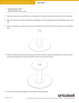
Unscrew the securing screws SW 8 (1) and
remove the cover (2).
0
Secure the PDC control module (1) to the stud bolt
on the inside of the cover (3) using two plastic nuts
(2). Connect branches A and B to the connections
on the PDC control module (1) with the same
colours and insert grommet C into the cover.
On cars with a trailer hitch module, slit open
the grommet C and thread branches A and B
through the grommet.
"
0
Fit the cover (1) and secure it with the four securing
screws SW 8 (2).
F 46 0782 EVA
2
1
1
F 46 0780 EVA
3
A
B
2
C
1
F 46 0781 EVA
1
2
2

EN/11
Retrofit / Installation kit No. 66 20 0 007 031
Installation Instructions No. 01 29 0 137 628 Issue date: 02.2002
7. To install the power supply wiring harness
0
0
0
0
0
0
Lay the power supply wiring harness
A
from the
PDC control module along the standard wiring
harness in the right sill to the fuse box above the
glove compartment.
In RHD cars the same installation route for
the power supply wiring harness is to be
used as in LHD cars. To do this the ties on
the power supply wiring harness also have to
be cut open.
"
0
Connect branch
B
on the power supply wiring
harness, green/white cable, to the fuse holder II,
A47 (1) (X10016) slot F 24, Pin 48 and insert a flat-
bladed fuse (2) 5A.
0
Connect the cables on the power supply wiring
harness to the appropriate joint connectors in the
joint connector box (1) as shown in the table
below:
0
Vehicles without a gong only
Cable
A1
with the blue/yellow cable Connector X428
Cable
A2
with the brown cable Connector X219
Cable
A3
with the white/red/yellow cable Connector X10116
Cable
A4
with the red/yellow cable Terminal R
Vehicles with a gong only
Cable
A1
with the blue/yellow cable Connector X428
Cable
A3
with the white/red/yellow cable Connector X10116
F 46 0783 EVA
B
A
1
3
5
7
9
11
13
15
16
18
20
22
24
26
28
30
32
34
2
1
B
F 46 0202 EVA
A2
A4
A1
A3
1
F 46 0206 EVA

EN/12
Retrofit / Installation kit No. 66 20 0 007 031
Installation Instructions No. 01 29 0 137 628 Issue date: 02.2002
7. To install the power supply wiring harness
0
0
0
0
Vehicles without a gong only
Cut the prepared cut-out (1) for the gong (2) out of
the footwell trim on the driver’s side (3) and insert
the gong (2).
Connect socket contact D1, blue/grey cable, to
the 1-pin socket casing D. Connect socket
contact C1, brown cable, to the 3-pin socket
casing C Pin 1 and socket contact C2, red/yellow
cable, to the 3-pin socket casing C Pin 3.
Connect the socket casing D,
C to the appropriate
slots on the gong:
1-pin socket casing D to slot T4 (X363)
3-pin socket casing C to slot T3 (X522)
Vehicles with a gong only
Connect socket contact D1, blue/grey cable, to
the 1-pin socket casing D and connect this to slot
T4 (X363) on the gong.
Tie back the cable lengths that are not
required.
"
0
Connect the blade terminal contact E, brown/
black cable, to the joint connector (1) (X217) near
the steering column in the footwell on the driver’s
side.
Tie back the cable lengths that are not required on
the RHD model.
Select the installation route of the cables so
that they cannot be damaged by moving
parts. Secure the joint connectors and
cables at suitable points using cable ties.
"
F 46 0208 EVA
12
11
10
13
E
F 46 0209 EVA

EN/13
Retrofit / Installation kit No. 66 20 0 007 031
Installation Instructions No. 01 29 0 137 628 Issue date: 02.2002
8. To assemble the car
Assemble the car again following the instructions for its dismantling in reverse order.
9. Coding
To ensure that the PDC retrofit system adjusts to the specific car perfectly the PDC control
module must be coded. The Mobile Diagnostic Computer MoDIC (III) or the DIS with CD version
15 (or higher) is required to code the PDC control module. It cannot be coded with an older
version.
The steps for this procedure are described briefly below:
Connect MoDiC (III) to the diagnostics plug in the car and switch on the ignition.
Ensure that there is sufficient battery voltage during the coding procedure, connect a
battery charger if necessary.
"
Select menu point “Coding/Program.”
After completing the coding switch off the ignition for approx. 10 seconds.
"
“Coding ZCS” <Enter>
“Coding via central coding key (ZCS)”
Version C15.0 (or higher) <Enter>
Select “Series E46“ <Enter>
“Retrofit” <Enter>
“PDC” <Enter>
“Automatic coding” <Yes>

EN/14
Retrofit / Installation kit No. 66 20 0 007 031
Installation Instructions No. 01 29 0 137 628 Issue date: 02.2002
10. Circuit diagram
0
X10116X428
12 4
X300
X363
H10
A81
X18013
0.5
BLGE
0.35
WSRTGE
8
1
0.5
GNWS
A47
1
F24
X10016
15<24
15<24 S_RS+ K-BUS PDCG
48
B34
12
X18020
0.35
GNSW
0.35
GEGR
12 11
D_WHLU_WHL
3
3
M_WHL
0.35
BRWS
B35
12
X18021
0.35
GNBR
0.35
GEGN
5 9
D_WHML
U_WHML
1
3
M_WHML
0.35
BRSW
B36
12
X18022
0.35
GNGR
0.35
GESW
48
D_WHMR
U_WHMR
7
3
M_WHMR
0.35
BRBL
B37
12
X18023
0.35
GNVI
0.35
GEBR
610
D_WHRU_WHR
2
3
M_WHR
0.35
BRGE
5A
X217
6
0.5
BRSW
31E
3
1
X10189
0.5
RTGE
X219
0.5
BR
31
VA
H10
X522
X522
0.35
BLGR
F 46 0207 EVA

EN/15
Retrofit / Installation kit No. 66 20 0 007 031
Installation Instructions No. 01 29 0 137 628 Issue date: 02.2002
10. Circuit diagram
A47 Fuse holder
A81 PDC plug casing
H10 Gong
X217 31E connector
X219 31 connector
X300 12-pin plug
X363 1-pin plug
X428 VB RS
X522 3-pin plug
X10016 Fuse holder
X10116 I bus connector
Terminal R Consumer cut-out connector
X18013 12-pin plug
X18020 3-pin plug
X18021 3-pin plug
X18022 3-pin plug
X18023 3-pin plug
B34 Rear left converter
B35 Rear centre left converter
B36 Rear centre right converter
B37 Rear right converter
/