Page is loading ...

RoGator 2009 & Newer AutoBoom®
UltraGlide XT Installation Manual
P/N 016-0233-005 Rev. E 2/17 E29134
Copyright 2014, 2015, 2016, 2017

While every effort has been made to ensure the accuracy of this document,
Raven Industries assumes no responsibility for omissions and errors. Nor is any
liability assumed for damages resulting from the use of information contained
herein.
Raven Industries shall not be responsible or liable for incidental or consequential
damages or a loss of anticipated benefits or profits, work stoppage or loss, or
impairment of data arising out of the use, or inability to use, this system or any of
its components. Raven Industries shall not be held responsible for any
modifications or repairs made outside our facilities, nor damages resulting from
inadequate maintenance of this system.
As with all wireless and satellite signals, several factors may affect the availability
and accuracy of wireless and satellite navigation and correction services (e.g.
GPS, GNSS, SBAS, etc.). Therefore, Raven Industries cannot guarantee the
accuracy, integrity, continuity, or availability of these services and cannot
guarantee the ability to use Raven systems, or products used as components of
systems, which rely upon the reception of these signals or availability of these
services. Raven Industries accepts no responsibility for the use of any of these
signals or services for other than the stated purpose.
Disclaimer

Table of Contents
Manual No. 016-0171-122 Rev. E i
Chapter 1 Important Safety Information............................................................................. 1
Hydraulic Safety ........................................................................................................................2
Electrical Safety ........................................................................................................................2
Chapter 2 Introduction............................................................................................................. 3
Preparing for Installation ...........................................................................................................3
Recommendations .................................................................................................................................................................4
Point of Reference .................................................................................................................................................................4
Hydraulic Fittings .......................................................................................................................4
Updates .....................................................................................................................................4
AutoBoom UltraGlide and UltraGlide XT Kit Contents ..............................................................6
Model Year 2009 ...................................................................................................................................................................6
Model Years 2010 - 2011 ..................................................................................................................................................11
Model Year 2012 & Newer ...............................................................................................................................................16
Hydraulic Installation Kit ....................................................................................................................................................21
Ultrasonic Sensor Bracket Kit. ..........................................................................................................................................22
Chapter 3 Hydraulic System Installation............................................................................ 23
Mount the AutoBoom Valve (If Applicable) ..............................................................................24
Install Fittings in the UltraGlide XT Valve ................................................................................25
Mount the UltraGlide XT Valve Assembly ................................................................................26
Install the Pressure and Tank Hoses .......................................................................................27
Install the UltraGlide XT Cylinders ..........................................................................................29
Install the Cylinder Hoses .......................................................................................................31
Hydraulic Schematic ...............................................................................................................35
Chapter 4 Sensor Installation................................................................................................ 37
Boom Sensor Mounting Locations ..........................................................................................37
Install the Sensors - UltraGlide Not Installed on the Machine .................................................38
Install the Boom Sensors ...................................................................................................................................................38
Install the Center Rack Sensor .........................................................................................................................................39
Install the Sensors - UltraGlide Installed on the Machine (If Applicable) .................................40
Mount the Boom Sensors .................................................................................................................................................40
Install the Center Rack Sensor .........................................................................................................................................40
Install the Rotary Sensor .........................................................................................................42
Chapter 5 Wiring Installation................................................................................................ 45
Wiring Connections .................................................................................................................45
Model Year 2012 & Newer RG Series Node and Harness Installation ....................................45
Install the Node Harness ...................................................................................................................................................45
Install the UltraGlide XT Node .........................................................................................................................................47
Install the Valve Harness ...................................................................................................................................................48
Model Year 2010-2011 - 9x4(H), 11x4(H), 13x6 Series Node and Harness Installation ..........50
Install the Node and Node Harness ..............................................................................................................................50
Install the Valve Harness ...................................................................................................................................................51

Table of Contents
ii Viper Pro Installation & Operation Manual
Connect the Sensor Cables ..............................................................................................................................................52
Install the Power/CAN Cable ...........................................................................................................................................52
Model Year 2009 Node and Harness Installation ....................................................................54
Install the UltraGlide XT Node ........................................................................................................................................54
Connect the Harness to the Boom Function Controls ...........................................................................................54
Install the Center Rack Control .......................................................................................................................................55
Connect the Harness Cable to the Sensors ...............................................................................................................56
Connect the Harness Cable to the Power Cable - Gen I Cable Only ...............................................................57
Connect the CAN/Power Cables - Gen I Cable Only ..............................................................................................57
Connect the Power Leads - Gen I Cable Only ...........................................................................................................58
Connect the Harness Cable to the Implement Extension Tee - Gen II Cable Only ....................................58
Install the UltraGlide XT Auxiliary Sensor Cable .....................................................................58
Wiring Diagram ........................................................................................................................60
2009 Wiring Schematic ......................................................................................................................................................60
2010-2011 Wiring Schematic ..........................................................................................................................................61
2012 & Newer Wiring Schematic ..................................................................................................................................62
Chapter 6 Startup Procedures.............................................................................................. 65
Verify the AutoBoom Hydraulic System Installation .................................................................65
Verify the UltraGlide XT Wiring ................................................................................................65
Calibrate the AutoBoom UltraGlide XT System .......................................................................66
Chapter 7 Replacement Parts............................................................................................... 67
Valve .......................................................................................................................................68
Sensors ...................................................................................................................................70

CHAPTER
1
Manual No. 016-0171-122 Rev. E 1
CHAPTER 1
IMPORTANT SAFETY
INFORMATION
Read this manual and the operation and safety instructions included with your implement and/or controller
carefully before installing the AutoBoom™ system.
• Follow all safety information presented within this manual.
• If you require assistance with any portion of the installation or service of your Raven equipment, contact your
local Raven dealer for support.
• Follow all safety labels affixed to the AutoBoom system components. Be sure to keep safety labels in good
condition and replace any missing or damaged labels. To obtain replacements for missing or damaged safety
labels, contact your local Raven dealer.
When operating the machine after installing AutoBoom, observe the following safety measures:
• Be alert and aware of surroundings.
• Do not operate AutoBoom or any agricultural equipment while under the influence of alcohol or an illegal
substance.
• Remain in the operator’s position in the machine at all times when AutoBoom is engaged.
• Disable AutoBoom when exiting from the operator’s seat and machine.
• Do not drive the machine with AutoBoom enabled on any public road.
• Determine and remain a safe working distance from other individuals. The operator is responsible for disabling
AutoBoom when the safe working distance has been diminished.
• Ensure AutoBoom is disabled prior to starting any maintenance work on AutoBoom or the machine.
• When starting the machine for the first time after installing AutoBoom, be sure that all persons stand clear, in
case a hose has not been properly tightened.
• The machine must remain stationary and switched off, with the booms unfolded, during installation or
maintenance.
NOTICE
WARNING
CAUTION

CHAPTER 1
2 Viper Pro Installation & Operation Manual
HYDRAULIC SAFETY
• Raven Industries recommends that appropriate protective equipment be worn at all times when working on the
hydraulic system.
• Never attempt to open or work on a hydraulic system with the equipment running. Care should always be
taken when opening a system that has been previously pressurized.
• Exercise caution when disconnecting the hydraulic hoses or purging is required, be aware that the hydraulic
fluid may be extremely hot and under high pressure.
• Any work performed on the hydraulic system must be done in accordance with the machine manufacturer’s
approved maintenance instructions.
• When installing AutoBoom hydraulics or performing diagnostics, maintenance, or routine service, ensure that
precautions are taken to prevent any foreign material or contaminants from being introduced into the
machine’s hydraulic system. Objects or materials that are able to bypass the machine’s hydraulic filtration
system will adversely reduce performance and possibly damage the AutoBoom hydraulic valves.
ELECTRICAL SAFETY
• Always verify that the power leads are connected to the correct polarity as marked. Reversing the power leads
could cause severe damage to the equipment.
• Ensure that the power cable is the last cable to be connected.
• Always disconnect batteries before performing electrical work.

CHAPTER
2
Manual No. 016-0171-122 Rev. E 3
CHAPTER 2
INTRODUCTION
Congratulations on your purchase of the Raven AutoBoom system! This system is designed to provide automated
boom height adjustment for agricultural equipment.This manual applies to the machines listed below.
MAKE: AGCO RoGator
YEAR: 2009
MODEL: 884, SS884, 1084, 1084C, SS1084, SSC1084, and 1286C
YEAR: 2010-2011
MODEL: 984, 984H, 994, 994H, 1184, 1184H, 1194, 1194H, 1386, and 1396
YEAR: 2012 & Newer
MODEL: RG900, RG900B, RG1100, RG1100B, RG1300, and RG1300B
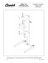
FIGURE 1. AGCO RoGator RG1100
PREPARING FOR INSTALLATION
Before installing AutoBoom:
• Park the machine on dry, clean, and level land.
• Leave the machine off during the installation process.
• Read the instructions in this manual as you complete the installation process.

CHAPTER 2
4 Viper Pro Installation & Operation Manual
RECOMMENDATIONS
Raven Industries recommends the following best practices before installing or operating the AutoBoom system for
the first time, at the start of the season, or when moving the AutoBoom system to another machine:
• Ensure the machine’s hydraulic filters have been recently changed and there are no issues with the machine’s
hydraulic system (e.g., pump issues, faulty hydraulic motors, fine metal deposits in the hydraulic hoses, etc.).
• Operate each of the machine’s boom hydraulic functions (i.e., tilt, fold, center rack, tongue extension, or other
hydraulic valve functions) three times to ensure the machine’s hydraulic valve is using fresh oil and debris is
flushed from the hydraulic hoses, valves, and filters.
• Upon installation of the AutoBoom system, operate the boom and center rack raise/lower functions through
the machine’s manual control functions first before operating them via the AutoBoom controller/field
computer to ensure the hydraulic system has been installed correctly and air is released from the system.
Raven Industries recommends the following best practices when installing the AutoBoom system.
• Use part numbers to identify the parts.
• Do not remove the plastic wrap or caps from parts until ready for installation.
Tools Ne ede d
The following tools are recommended for installation of the AutoBoom system:
• SAE standard-sized wrenches
• Cable ties
•Set of tools
POINT OF REFERENCE
The instructions in this manual assume that you are standing behind the machine, looking toward the cab.
HYDRAULIC FITTINGS
This manual may reference the following types of hydraulic fittings:
• SAE O-ring fittings
• ORFS (O-Ring Face Seal) fittings
• JIC fittings
UPDATES
Software and manual updates are available on the Raven Applied Technology website:
JIC fitting
ORFS fitting
SAE O-ring fitting

2
Manual No. 016-0171-122 Rev. E 5
INTRODUCTION
http://www.ravenhelp.com
At Raven Industries, we strive to make your experience with our products as rewarding as
possible. One way to improve this experience is to provide us with feedback on this manual.
Your feedback will help shape the future of our product documentation and the overall service we
provide. We appreciate the opportunity to see ourselves as our customers see us and are eager
to gather ideas on how we have been helping or how we can do better.
To serve you best, please send an email with the following information to
techwriting@ravenind.com
-Viper Pro Installation & Operation Manual
-Manual No. 016-0171-122 Rev. E
-Any comments or feedback (include chapter or page numbers if applicable).
-Let us know how long have you been using this or other Raven products.
We will not share your email or any information you provide with anyone else. Your feedback is
valued and extremely important to us.
Thank you for your time.

CHAPTER 2
6 Viper Pro Installation & Operation Manual
AUTOBOOM ULTRAGLIDE AND ULTRAGLIDE XT KIT CONTENTS
MODEL YEAR 2009
TABLE 1. AutoBoom UltraGlide and UltraGlide XT Kit Contents
Picture Item Description Part Number
2009 Gen I
117-0233-010
Qty.
2009 Gen I
117-0234-010
Qty
2009 Gen II
117-0233-011
Qty.
2009 Gen II
117-0234-011
Qty.
Not Pictured
Manual - AutoBoom
Calibration and Operation
016-0130-062 1 1 1 1
Not Pictured
Manual - RoGator UltraGlide
XT Installation
016-0233-005 1 1 1 1
Valve - AutoBoom Add-On
Hydraulic
063-0131-131 1 N/A 1 N/A
Valve - Autoboom XT
Hydraulic
063-0131-154 1 1 1 1
Node - UltraGlide XT 063-0130-023 1 1 1 1
Sensor - Left Ultrasonic 063-0130-014 1 1 1 1
Sensor - Ultrasonic Sensor 063-0130-026 4 N/A 4 N/A
Sensor - Rotary Non-Contact
Con-X-All Connector
063-0181-018 1 1 1 1
Bracket - Hydraulic Valve
Mounting
107-0171-619 1 N/A 1 N/A

2
Manual No. 016-0171-122 Rev. E 7
INTRODUCTION
Bracket - Rotary Sensor
Mounting
107-0172-1771111
Bracket - Rotary Sensor Bolt
Mounting
107-0172-1781111
Bracket - UltraGlide XT Valve
Mount
107-0172-1791111
Bracket - XT Rotary Sensor
Mounting
107-0172-2681111
Bracket - XT Sensor Mounting107-0172-3491111
Bracket - Ultrasonic Sensor
Weldment Mounting
116-0159-6841111
Cable - 70’ Sensor Extension 115-0171-527 2 2 2 2
Cable - AGCO RoGator Boom
Sense Adapter
115-0171-546 4 N/A 4 N/A
Cable - 40’ Sensor Extension 115-0171-602 2 2 2 2
Cable - AutoBoom Power 115-0233-007 1 N/A N/A N/A
TABLE 1. AutoBoom UltraGlide and UltraGlide XT Kit Contents
Picture Item Description Part Number
2009 Gen I
117-0233-010
Qty.
2009 Gen I
117-0234-010
Qty
2009 Gen II
117-0233-011
Qty.
2009 Gen II
117-0234-011
Qty.

CHAPTER 2
8 Viper Pro Installation & Operation Manual
Cable - Deutsch Center Rack
Control Boom Sense Adapter
115-0230-039 2 N/A 2 N/A
Cable - 2 -in Deutsch Power
Split
115-0230-070 1 N/A 1 N/A
Cable - UltraGlide XT Node
Harness
115-0230-095 N/A N/A 1 1
Cable - UltraGlide XT Rotary
Sensor
115-0230-110 1 1 1 1
Cable - UltraGlide XT Valve
Harness
115-0230-116 1 1 N/A N/A
Cylinder - 1.5” x 8” x 0.75”
Hydraulic
334-0004-
006
2222
U-Bolt - 3-1/16” W x 4” L x 3/8”
Thread
107-0171-608 2 2 2 2
U-Bolt - 1-9/16” W x 2-1/2” L x
3/8” Thread
107-0171-611 8 N/A 8 N/A
U-Bolt - 2-9/16” W x 3-1/2” L x
3/8” Thread
107-0171-616 4 2 4 2
U-Bolt - 3-1/16” W x 2-1/4” L x
3/8” - 16 Thread
107-0172-2881111
TABLE 1. AutoBoom UltraGlide and UltraGlide XT Kit Contents
Picture Item Description Part Number
2009 Gen I
117-0233-010
Qty.
2009 Gen I
117-0234-010
Qty
2009 Gen II
117-0233-011
Qty.
2009 Gen II
117-0234-011
Qty.

2
Manual No. 016-0171-122 Rev. E 9
INTRODUCTION
Bolt - 5/16”-18 x 1-3/4” Hex 311-0052-108 1 N/A 1 N/A
Bolt - 5/16” - 18 x 2-1/2” Hex 311-0052-111 3 N/A 3 N/A
Bolt - 5/16” - 18 UNC x 3”
Machine
311-0052-113 2 2 2 2
Bolt - 5/16” - 18 UNC X 3-1/2”
Machine
311-0052-1151111
Bolt - 3/8” - 16 UNC 1-1/4”
Machine
311-0054-081 7 4 7 4
Bolt - 1/2” - 13 UNC x 3-1/2”
Machine
311-0058-1051111
Bolt - 3/4” - 10 UNC x 4”
Machine
311-0062-1604444
Screw - #8 - 32” UNC 2 x 1/2”
Phillips Panhead Machine
311-0001-013 3 3 3 3
Screw - #8 - 32” UNC x 1-1/4”
Phillips Panhead Machine
311-0001-023 3 3 3 3
Nut - #8-32 UNC - 2B Hex 312-1001-020 6 6 6 6
TABLE 1. AutoBoom UltraGlide and UltraGlide XT Kit Contents
Picture Item Description Part Number
2009 Gen I
117-0233-010
Qty.
2009 Gen I
117-0234-010
Qty
2009 Gen II
117-0233-011
Qty.
2009 Gen II
117-0234-011
Qty.

CHAPTER 2
10 Viper Pro Installation & Operation Manual
Nut - 3/8” - 16 Zinc Flanged
Lock
312-1001-164 34 14 34 14
Nut - 5/16” - 18 Nylon Insert
Lock
312-4000-059 3 3 3 3
Nut - 3/8” - 16 Nylon Insert
Lock
312-4000-061 3 N/A 3 N/A
Nut - 1/2” - 13 Nylon Insert
Lock
312-4000-065 1 1 1 1
Nut - 3/4” - 10 Nylon Insert
Lock
312-4000-071 4 4 4 4
O-Ring - 9/16” ID Buna-N 219-0001-015 4 N/A 4 N/A
Washer - 5/16” Flat 313-2300-011 8 8 8 8
Washer - 1/2” Flat 313-2300-017 2 2 2 2
Washer - 3/4” Flat 313-2300-023 8 8 8 8
Washer - #8 .019” ID x .044”
OD x .049” Thick
313-2300-123 3 3 3 3
TABLE 1. AutoBoom UltraGlide and UltraGlide XT Kit Contents
Picture Item Description Part Number
2009 Gen I
117-0233-010
Qty.
2009 Gen I
117-0234-010
Qty
2009 Gen II
117-0233-011
Qty.
2009 Gen II
117-0234-011
Qty.

2
Manual No. 016-0171-122 Rev. E 11
INTRODUCTION
MODEL YEARS 2010 - 2011
TABLE 2. AutoBoom UltraGlide and UltraGlide XT Installation Kits
Picture Item Description Part Number
117-0233-008
Qty.
117-0234-008
Qty.
Not Pictured
Manual - AutoBoom Calibration and
Operation
016-0130-062 1 1
Not Pictured
Manual - RoGator UltraGlide XT
Installation
016-0233-005 1 1
Valve - AutoBoom Add-On Hydraulic 063-0131-131 1 N/A
Valve - AutoBoom XT Hydraulic 063-0131-154 1 1
Node - UltraGlide XT 063-0130-023 1 1
Sensor - Left Ultrasonic 063-0130-014 1 1
Sensor - Ultrasonic Sensor 063-0130-026 4 N/A
Sensor - Rotary Non-Contact Con-X-All
Connector
063-0181-018 1 1
Bracket - Rotary Sensor Mounting 107-0172-177 1 1

CHAPTER 2
12 Viper Pro Installation & Operation Manual
Bracket - Rotary Sensor Bolt Mounting 107-0172-178 1 1
Bracket - UltraGlide XT Valve Mounting 107-0172-179 1 1
Bracket - UltraGlide XT Rotary Sensor
Mounting
107-0172-268 1 1
Bracket - UltraGlide Node Mounting 107-0172-348 1 N/A
Bracket - UltraGlide XT Sensor Mounting 107-0172-349 1 1
Bracket - Ultrasonic Sensor Weldment
Mounting
116-0159-684 1 1
Cable - 70’ Sensor Extension 115-0171-527 2 2
Cable - 40’ Sensor Extension 115-0171-602 2 2
Cable - RoGator 2010-2011 Aftermarket
Node Harness
115-0230-104 1 1
Cable - RoGator 2010-2011 Aftermarket
CAN/Power
115-0230-105 1 1
TABLE 2. AutoBoom UltraGlide and UltraGlide XT Installation Kits
Picture Item Description Part Number
117-0233-008
Qty.
117-0234-008
Qty.

2
Manual No. 016-0171-122 Rev. E 13
INTRODUCTION
Cable - RoGator 2010-2011 Aftermarket
Valve and Sensor Harness
115-0230-106 1 1
Cable - UltraGlide XT Rotary Sensor 115-0230-110 1 1
Cylinder - 1.5” x 8” x 0.75” Hydraulic
334-0004-
006
22
U-Bolt - 3-1/16” W x 4” L x 3/8” Thread 107-0171-608 2 2
U-Bolt - 1-9/16” W x 2-1/2” L x 3/8” Thread 107-0171-611 8 N/A
U-Bolt - 2-9/16” W x 3-1/2” L x 3/8”
Thread
107-0171-616 2 2
U-Bolt - 3-1/16” W x 2-1/4” L x 3/8” - 16
Thread
107-0172-288 1 1
Bolt - 5/16”-18 x 1-3/4” 311-0052-108 1 N/A
Bolt - 5/16” - 18 x 2-1/2” Hex 311-0052-111 3 N/A
Bolt - 5/16” - 18 UNC x 3” Machine 311-0052-113 2 2
TABLE 2. AutoBoom UltraGlide and UltraGlide XT Installation Kits
Picture Item Description Part Number
117-0233-008
Qty.
117-0234-008
Qty.

CHAPTER 2
14 Viper Pro Installation & Operation Manual
Bolt - 5/16” - 18 UNC X 3-1/2” Machine 311-0052-115 1 1
Bolt - 3/8” - 16 UNC 1-1/4” Machine 311-0054-081 7 4
Bolt - 1/2” - 13 UNC x 3-1/2” Machine 311-0058-105 1 1
Bolt - 3/4” - 10 UNC x 4” Machine 311-0062-160 4 4
Screw - #8-32 UNC 2 x 1/2” Phillips
Panhead Machine
311-0001-013 3 3
Screw - #8-32 UNC x 1-1/4” Phillips
Panhead Machine
311-0001-023 3 3
Screw - 1/4”-20 X 3/4” Self-Tapping 311-0001-345 1 N/A
Nut - #8-32 UNC - 2B Hex 312-1001-020 6 6
Nut - 3/8” - 16 Zinc Flanged Lock 312-1001-164 30 14
Nut - 5/16” - 18 Nylon Insert Lock 312-4000-059 3 3
TABLE 2. AutoBoom UltraGlide and UltraGlide XT Installation Kits
Picture Item Description Part Number
117-0233-008
Qty.
117-0234-008
Qty.

2
Manual No. 016-0171-122 Rev. E 15
INTRODUCTION
Nut - 3/8” - 16 Nylon Insert Lock 312-4000-061 3 N/A
Nut - 1/2” - 13 Nylon Insert Lock 312-4000-065 1 1
Nut - 3/4” - 10 Nylon Insert Lock 312-4000-071 4 4
O-Ring, - 9/16” ID Buna-N 219-0001-015 4 N/A
Washer - 5/16” Split Lock 313-1000-019 4 N/A
Washer - 5/16” Flat 313-2300-011 8 8
Washer - 1/2” Flat 313-2300-017 2 2
Washer - 3/4” Flat 313-2300-023 8 8
Washer - 0.019” ID x 0.044” OD x 0.049”
Thick
313-2300-123 3 3
TABLE 2. AutoBoom UltraGlide and UltraGlide XT Installation Kits
Picture Item Description Part Number
117-0233-008
Qty.
117-0234-008
Qty.

CHAPTER 2
16 Viper Pro Installation & Operation Manual
MODEL YEAR 2012 & NEWER
TABLE 3. AutoBoom UltraGlide and UltraGlide XT Installation Kits
Picture Item Description Part Number
117-0233-005
Qty.
117-0233-016
Qty.
117-0233-017
Qty.
117-0233-018
Qty.
117-0234-005
Qty.
117-0234-016
Qty.
117-0234-017
Qty.
117-0234-018
Qty.
Not Pictured
Manual - AutoBoom
Calibration and
Operation
016-0130-06211111111
Not Pictured
Manual - RoGator
UltraGlide XT
Installation
016-0233-00511111111
Valve - AutoBoom
Add-On Hydraulic
063-0131-131 1111
N/
A
N/
A
N/
A
N/
A
Valve - UltraGlide XT
AutoBoom Hydraulic
063-0131-154 11111111
Node - UltraGlide XT
AutoBoom
063-0130-023 1
N/
A
1
N/
A
1
N/
A
1
N/
A
Node - UltraGlide ISO
AutoBoom
063-0130-024
N/
A
1
N/
A
1
N/
A
1
N/
A
1
Sensor - Center
Ultrasonic
063-0130-014 11111111
Sensor - Ultrasonic 063-0130-026 4444
N/
A
N/
A
N/
A
N/
A
Sensor Assembly -
Con-X-All Non-
Contact Rotary
063-0181-018 11111111
/