
P/N: 1802031312031
*1802031312031*
AWK-3131A-M12-RCC
Quick Installation Guide
Moxa AirWorks
Edition 2.0, January 2019
Technical Support Contact Information
www.moxa.com/support
Moxa Americas:
Toll
-free: 1-888-669-2872
Tel:
1-714-528-6777
Fax:
1-714-528-6778
Moxa China (Shanghai office):
To
ll-free: 800-820-5036
Tel:
+86-21-5258-9955
Fax:
+86-21-5258-5505
Moxa Europe:
Tel:
+49-89-3 70 03 99-0
Fax:
+49-89-3 70 03 99-99
Moxa Asia-Pacific:
Tel:
+886-2-8919-1230
Fax:
+886-2-8919-1231
Moxa India:
Tel:
+91-80-4172-9088
Fax:
+91-80-4132-1045
2019 Moxa Inc. All rights reserved.

- 2 -
Overview
Moxa’s new AWK-3131A-M12-RCC is a 3-in-1 industrial AP/client device
designed specifically for rail carriage-to-carriage communication and can
provide up to 300 Mbps speed with IEEE 802.11n technology. The
AWK-3131A-M12-RCC combines two adjacent 20 MHz channels into a
single 40 MHz channel to deliver a potent combination of greater
reliability and more bandwidth. The dual DC power inputs increase the
reliability of the power supply, and the AWK-3131A-M12-RCC can be
powered via PoE to make deployment easier. The AWK-3131A-M12-RCC
can operate on either the 2.4 or 5 GHz bands and is backward-compatible
with existing 802.11a/b/g deployments to future-proof your wireless
investments.
Package Checklist
• AWK-3131A-M12-RCC
• Cable holder with one screw
• 2 plastic RJ45 protective caps for Console port
• DIN-rail kit (preinstalled)
• Quick installation guide (printed)
• Warranty card
If any of these items is missing or damaged, please contact your
customer service representative for assistance.
NOTE
Antennas are not included and should be purchased separately.
The AWK is certified with 2
dBi omni-directional antennas with
QMA to RP-SMA adapters.
Installation and Configuration
Before installing the AWK-3131A-M12-RCC, make sure that all items in
the Package Checklist are in the box. In addition, you will need access to
a notebook computer or PC equipped with an Ethernet port. The
AWK-3131A-M12-RCC has a default IP address that you must use when
connecting to the device for the first time.
Step 1: Select the power source
The AWK-3131A-M12-RCC can be powered by a DC power input or PoE
(Power over Ethernet). The AWK-3131A-M12-RCC will use whichever
power source you choose.
Step 2: Connect the AWK-3131A-M12-RCC to a notebook
or PC
Since the AWK-3131A-M12-RCC supports MDI/MDI-X auto-sensing, you
can use either a straight-through cable or crossover cable to connect the
AWK-3131A-M12-RCC to a computer. If the LAN LED indicator on the
AWK-3131A-M12-RCC port lights up, it means the connection is
established.

- 3 -
Step 3: Set up the computer’s IP address
Set an IP address on the same subnet as the AWK-3131A-M12-RCC.
Since the AWK-3131A-M12-RCC’s default IP address is 192.168.127.253,
and the subnet mask is 255.255.255.0, you should set the IP address of
the computer to 192.168.127.xxx and subnet mask to 255.255.255.0.
Step 4: Use the web-based manager to configure
AWK-3131A-M12-RCC
Open your computer’s web browser and then type
http://192.168.127.253 in the address field to access the homepage
of the web-based management. Before the homepage opens, you will
need to enter the user name and password. For first-time configuration,
enter the default user name and password and then click on the Login
button:
Username: admin
Password: moxa
ATTENTION
For security reasons, we strongly recommend changing the
password. To do so,
select Maintenance
Password
, and then
follow the on-screen instructions.
Step 5: Select the operation mode for the
AWK-3131A-M12-RCC
By default, the AWK-3131A-M12-RCC’s operation mode is set to AP. You
can change the setting in Wireless Settings Basic Wireless
Settings if you would like to use the Client mode.
NOTE
To make the change effective, you must click Save Configuration
to save the cha
nge or the Save and Restart button to apply all
changes.

- 4 -
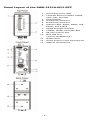
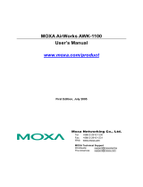
Panel Layout of the AWK-3131A-M12-RCC
1. Grounding screw (M5)
2. Terminal block for PWR1, PWR2,
relay, DI0, and DI1
3. Reset button
4. A antenna connector
5. B antenna connector
6. System LEDs: PWR1, PWR2, PoE,
FAULT, and STATE
7. Signal strength indicator
8. CLIENT, WLAN, and LAN LEDs
9. RS-232 console port
10.
M12 LAN Port:
10/100/1000BaseT(X)
11.
Model name
12.
Screw holes for wall mounting kit
13.
DIN-rail mounting kit

- 5 -
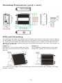
Mounting Dimensions (unit = mm)
DIN-rail Mounting
The aluminum DIN-rail attachment plate should be fixed to the back panel
of the AWK-3131A-M12-RCC when you take it out of the box. If you need
to reattach the DIN-rail attachment plate to the AWK-3131A-M12-RCC,
make sure the stiff metal spring is situated towards the top, as shown in
the figures below.
STEP 1:
Insert the top of the DIN
rail into
the slot just
below the stiff metal
spring.
STEP 2:
The DIN
-rail attachment unit will
snap into place as shown below.
To remove the AWK-3131A-M12-RCC from the DIN rail, simply reverse
Steps 1 and 2.

- 6 -
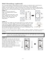
Wall Mounting (optional)
For transportation applications that require an EN 50155 certification
report, we strongly recommend the purchase of the optional
AWK-3131A-M12-RCC wall-mounting kit, which has passed EN 50155
testing. This wall-mounting kit is also convenient for other applications
that require mounting the AWK-3131A-M12-RCC to a wall.
STEP 1:
Remove the aluminum
DIN
-rail attachment plate
from the
AWK
-3131A-M12-RCC, and
then attach the wall mount
plates with M3 sc
rews, as
shown in the adjacent
diagrams.
STEP 2:
Mounting the
AWK-3131A-M12-
RCC to a wall requires
4
screws. Use the AWK-3131A-M12-
RCC device, with
wall mount plates attached, as a guide to mark the
correct locations of the
4 screws. The heads of the
sc
rews should be less than 6.0 mm in diameter, and
the
shafts should be less than 3.5 mm in diameter, as
shown in the figure at the right.
Do not screw the screws in all the way—leave a space of about 2 mm to
allow room for sliding the wall mount panel between the wall and the
screws.
NOTE
Test the screw head and shank size by inserting the screw into
one of the keyhole shaped apertures of the Wall Mounting Plates
before it is screwed into the wall.
STEP 3:
Once the screws are fixed into
the wall, inse
rt the four screw
heads through the large opening
of the keyhole
-shaped
apertures, and then slide the
AWK
-3131A-M12-RCC
downwards, as indicated to the
right. Tighten the three screws
for added stability.

- 7 -
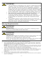
WARNING
•
Th
is equipment is intended to be used in a Restricted Access
Location, such as a
dedicated computer room, a cabinet, or
space specially reserved for device installation onboard a
train. Access can only be gained by SERVICE PERSONS
or by
USERS who have been instructed to comply with the
safety
rules thereby
avoiding casualties from electric shock, cutting
from a sharp edge, heat from a metallic surface, and so on.
•
Service persons or users have to pay special attention and
take special precautions before handling equipment.
•
Access is to be controlled through the use of a lock and key or
a security identity system, controlled by the authority
responsible for the location. Only authorized, well-trained
professionals are allowed to access the restricted access
location.
•
The metallic surface of the product may be hot when it is
installed in cabinets, places with direct sunlight, or next to a
high heat source. Pay special attention or use special
protection before handling equipment.
Wiring Requirements
WARNING
Safety First!
Be sure to disconnect the power cord before installing and/or
wiring your Moxa AWK-3131A-M12-RCC.
WARNING
Safety First!
Calculate the maximum possible current in each power wire and
common wire. Observe all electrical codes dictating the
maximum current allowed for each wire size.
If the current goes above the maximum ratings, the wiring could
overheat, causing serious damage to your equipment.
You should also pay attention to the following items:
• Use separate paths to route wiring for power and devices. If power
wiring and device wiring paths must cross, make sure the wires are
perpendicular at the intersection point.
NOTE: Do not run signal or communications wiring and power wiring
in the same wire conduit. To avoid interference, wires with different
signal characteristics should be routed separately.
• You can use the type of signal transmitted through a wire to
determine which wires should be kept separate. The rule of thumb is
that wiring with similar electrical characteristics can be bundled
together.
• Keep input wiring and output wiring separate.
• It is strongly advised that you label wiring to all devices in the system
when necessary.

- 8 -
ATTENTION
T
his product is intended to be supplied by a Listed Power Unit
marked
“Class 2” or “LPS” and rated O/P: 12 to 48 VDC
, minimum
6 W (12 V to 48V), 25°C.
ATTENTION
Make sure
the external power adapter (includes power cords an
d
plug assemblies) provided with the unit is certified and suitable
for use in your country.
ATTENTION
Do not use the PoE Injector. Instead, please use an IEEE802.3af
or IEEE802.3at compliant PSE (Power Sourcing Equipment
) for
PoE (Power over Ethernet) device.
Grounding the Moxa AWK-3131A-M12-RCC
Grounding and wire routing help limit the effects of noise due to
electromagnetic interference (EMI). Run the ground connection from the
ground screw to the grounding surface prior to connecting devices.
ATTENTION
This product is intended to be mounted to a well
-grounded
mounting surface, such as a metal panel.
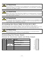
Connecting the Power Input
Pinouts for the Power Inputs and Relay Output
Pin
Name
Usage
1
V1+
DC Power Input 1
2
V1-
3
V2+
DC Power Input 2
4
V2-
5
Relay Output
6
7
I1
Digital Input
8
COM_1
Digital Input GND
9
I2
Digital Input
10
COM_2
Digital Input GND

- 9 -
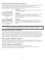
Wiring the Dual Power Inputs
The top two pairs of contacts of the 10-contact terminal block connector
on the AWK-3131A-M12-RCC’s top panel are used for the
AWK-3131A-M12-RCC’s two DC inputs. Top and front views of the
terminal block connector are shown below.
STEP 1:
Insert the negative/positive DC wires into the
V
-/V+ terminals.
STEP 2:
To keep the DC wires from pulling
loose, use a
small flat
-blade screwdriver to tighten the
wire
-clamp screws on the front of the terminal
block connector.
STEP 3:
Insert the plastic terminal block connector
prongs into the terminal
block receptor, which is
located on
the AWK-3131A-M12-RCC’s top
panel.
NOTE
Before connecting the AWK
-3131A-M12-RCC to the DC power
inputs, make sure the DC power source voltage is stable.
Wiring the Relay Contact
The AWK-3131A-M12-RCC has one relay output, which consists of the
two contacts of the terminal block on the AWK-3131A-M12-RCC’s top
panel. The two wires attached to the Relay contacts form an open circuit
when a user-configured event, such as the network connection status
change, DI0/1 status change, or power status change, is triggered. If a
user-configured event does not occur, the Relay circuit will be closed.
Wiring the Digital Inputs
The AWK-3131A-M12-RCC has two sets of digital input—DI0 and DI1.
Each DI comprises two contacts of the 10-pin terminal block connector on
the AWK-3131A-M12-RCC’s top panel.
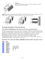
Cable Holder Installation
You can attach the cable holder to the bottom of the
AWK-3131A-M12-RCC. This helps to keep cabling neat and avoid
accidents that result from untidy cables.

- 10 -
STEP 1:
Screw the cable holder onto the bottom of the
AWK
-3131A-M12-RCC.
STEP 2:
After mounting the AWK-3131A-M12-RCC and plugging in the
LAN cable, tighten the cable along the device and wall.
Communication Connections
10/100/1000BaseT(X) Ethernet Port Connection
All AWK-3131A-M12-RCCs have a 10/100/1000BaseT(X) Ethernet port
(8-pin shielded M12 connector with A coding). The 10/100/1000TX port
located on the AWK-3131A-M12-RCC front panel is used to connect to
Ethernet-enabled devices. Most users configure this port for Auto
MDI/MDI-X mode, in which case the port’s pinouts are adjusted
automatically depending on the type of Ethernet cable used
(straight-through or cross-over), and the type of device (NIC-type or
HUB/Switch-type) connected to the port.
Pinouts for the 10/100/1000BaseT(X) M12 (8-pin) Port

- 11 -
RS-232 Connection
The AWK-3131A-M12-RCC has one RS-232 (8-pin RJ45) console port on
the front panel. Use either an RJ45-to-DB9 or RJ45-to-DB25 cable to
connect the AWK-3131A-M12-RCC console port to your PC’s COM port.
You may then use a console terminal program to access the
AWK-3131A-M12-RCC for console configuration.
Console Pinouts for 10-pin or 8-pin RJ45
10-Pin
Description
8-Pin
1
–
2
DSR
1
3
RTS
2
4
GND
3
5
TxD
4
6
RxD
5
7
DCD
6
8
CTS
7
9
DTR
8
10
–
ATTENTION
Although the isolated power module and housing insulation are
both built in
into the AWK-3131A-M12-RCC, it is recommended
that
the AWK-3131A-M12-RCC devices are attached to a
galvanically iso
lated power supply or a DC/DC power isolator is
used, both being compliant with the EN 50155 standard.
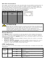
Reset Button
The RESET button is located on the top panel of the AWK-3131A-RCC.
You can reboot the AWK-3131A-M12-RCC or reset it to factory default
settings by pressing the RESET button with a pointed object such as an
unfolded paper clip.
• System reboot: Hold the RESET button down for under 5 seconds
and then release.
• Reset to factory default: Hold the RESET button down for over 5
seconds until the STATE LED starts blinking green. Release the
button to reset the AWK-3131A-M12-RCC.
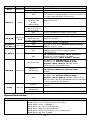
LED Indicators
The front panel of the Moxa AWK-3131A-M12-RCC contains several LED
indicators:
LED
Color
State
Description
PWR1 Green
On
Power is being supplied from power
input 1.
Off
Power is not being supplied from
power input 1.
PWR2 Green
On
Power is being supplied from power
input 2.
Off
Power is not being supplied from
power input 2.

- 12 -
LED
Color
State
Description
PoE Amber
On
Power is being supplied via PoE.
Off
Power is not being supplied via PoE.
FAULT Red
On
System is booting or
A system configuration error exists
or
A relay event has occurred
Blinking
(slowly at
1-sec
intervals)
Cannot get an IP address from the
DHCP server
Blinking (fast
at 0.5-sec
intervals)
IP address conflict
Off
Error condition does not exist.
STATE
Green/
Red
Green
Software Ready
Green,
blinking at
1-sec intervals
The AWK has been located by AWK
Search Utility
Red
Booting error condition
SIGNAL
(5 LEDs)
Green
On
Signal level (for Client/Slave/ACC
Slave mode only)
Off
CLIENT Green
On
WLAN is in Client/Slave mode or ACC
Slave mode with connection
established.
Off
AP/Master/Sniffer/ACC Master
mode or connection is NOT
established in ACC Slave mode.
WLAN Amber
Amber On
WLAN is in
AP
/
Master
mode.
WLAN is in Client/Slave/ACC
Master/ACC Slave mode with
connection established.
Amber,
blinking
Traffic in
AP/Client/Master/Slave/ACC
mode.
Off
WLAN is in Sniffer mode.
WLAN is in Client/Slave/ACC
Master/ACC Slave mode without a
connection being established or
WLAN
is not working properly.
LAN Green
Green
LAN port’s 10/100/1000 Mbps link is
active.
Green,
blinking
Data traffic at the LAN port.
Green Off
LAN port is disconnected.
Specifications
WLAN Interface
Standards
IEEE 802.11a/b/g/n for Wireless LAN
IEEE 802.11i for Wireless Security
IEEE 802.3 for 10BaseT
IEEE 802.3u for 100BaseTX
IEEE 802.3ab for 1000BaseT
IEEE 802.3af for Power-over-Ethernet
IEEE 802.1Q for VLAN

- 13 -
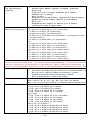
Spread Spectrum
and Modulation
(typical)
•
DSSS with DBPSK, DQPSK, CCK
• OFDM with BPSK, QPSK, 16QAM, 64QAM
• 802.11b:
CCK @ 11/5.5 Mbps, DQPSK @ 2 Mbps,
DBPSK @ 11 Mbps
• 802.11a/g:
64QAM @ 54/48 Mbps, 16QAM @ 36/24 Mbps,
QPSK @ 18/12 Mbps, BPSK @ 9/6 Mbps
• 802.11n:
64QAM@300 Mbps to BPSK @ 6.5 Mbps
(multiple rates supported)
Operating Channels
(central frequency)
US:
• 2.412 to 2.462 GHz (11 channels)
• 5.180 to 5.240 (4 channels)
• 5.260 to 5.320 (4 channels)*
• 5.500 to 5.700 GHz (8 channels, excluding 5.600
to 5.640 GHz)*
• 5.745 to 5.825 GHz (5 channels)
EU:
• 2.412 to 2.472 GHz (13 channels)
• 5.180 to 5.240 GHz (4 channels)
• 5.260 to 5.320 GHz (4 channels)*
• 5.500 to 5.700 GHz (11 channels)*
JP:
• 2.412 to 2.484 GHz (14 channels)
• 5.180 to 5.240 GHz (4 channels)
• 5.260 to 5.320 GHz (4 channels)*
• 5.500 to 5.700 GHz (11 channels)*
*DFS (Dynamic Frequency Selection) channel support: In AP mode, when
a radar signal is detected, the device will automatically switch to another
channel. However according to regulations, after switching channels, a
60-second availability check period is required before starting the service
Security
• SSID broadcast enable/disable
• Firewall for MAC/IP/Protocol/Port-based filtering
• 64-bit and 128-bit WEP encryption, WPA /
WPA2-Personal and Enterprise (IEEE
802.1X/RADIUS, TKIP and AES)
Transmission Rates
802.11b: 1, 2, 5.5, 11 Mbps
802.11a/g: 6, 9, 12, 18, 24, 36, 48, 54 Mbps
802.11n: 6.5 to 300 Mbps (multiple rates supported)
TX Transmit Power
802.11b:
• Typ. 26±1.5 dBm @ 1 Mbps
• Typ. 26±1.5 dBm @ 2 Mbps
• Typ. 26±1.5 dBm @ 5.5 Mbps
• Typ. 25±1.5 dBm @ 11 Mbps
802.11g:
• Typ. 23±1.5 dBm @ 6 to 24 Mbps
• Typ. 21±1.5 dBm @ 36 Mbps
• Typ. 19±1.5 dBm @ 48 Mbps
• Typ. 18±1.5 dBm @ 54 Mbps
802.11n (2.4 GHz):
• Typ. 23±1.5dBm @ MCS0 20 MHz
• Typ. 21±1.5dBm @ MCS1 20 MHz
• Typ. 21±1.5dBm @ MCS2 20 MHz
• Typ. 21±1.5dBm @ MCS3 20 MHz

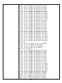
- 14 -
• Typ. 20±1.5dBm @ MCS4 20 MHz
• Typ. 19±1.5dBm @ MCS5 20 MHz
• Typ. 18±1.5dBm @ MCS6 20 MHz
• Typ. 18±1.5dBm @ MCS7 20 MHz
• Typ. 23±1.5dBm @ MCS8 20 MHz
• Typ. 21±1.5dBm @ MCS9 20 MHz
• Typ. 21±1.5dBm @ MCS10 20 MHz
• Typ. 21±1.5dBm @ MCS11 20 MHz
• Typ. 20±1.5dBm @ MCS12 20 MHz
• Typ. 19±1.5dBm @ MCS13 20 MHz
• Typ. 18±1.5dBm @ MCS14 20 MHz
• Typ. 18±1.5dBm @ MCS15 20 MHz
• Typ. 23±1.5dBm @ MCS0 40 MHz
• Typ. 20±1.5dBm @ MCS1 40 MHz
• Typ. 20±1.5dBm @ MCS2 40 MHz
• Typ. 20±1.5dBm @ MCS3 40 MHz
• Typ. 19±1.5dBm @ MCS4 40 MHz
• Typ. 19±1.5dBm @ MCS5 40 MHz
• Typ. 18±1.5dBm @ MCS6 40 MHz
• Typ. 17±1.5dBm @ MCS7 40 MHz
• Typ. 23±1.5dBm @ MCS8 40 MHz
• Typ. 20±1.5dBm @ MCS9 40 MHz
• Typ. 20±1.5dBm @ MCS10 40 MHz
• Typ. 20±1.5dBm @ MCS11 40 MHz
• Typ. 20±1.5dBm @ MCS12 40 MHz
• Typ. 19±1.5dBm @ MCS13 40 MHz
• Typ. 18±1.5dBm @ MCS14 40 MHz
• Typ. 17±1.5dBm @ MCS15 40 MHz
802.11a:
• Typ. 23±1.5 dBm @ 6 to 24 Mbps
• Typ. 21±1.5 dBm @ 36 Mbps
• Typ. 20±1.5 dBm @ 48 Mbps
• Typ. 18±.5 dBm @ 54 Mbps
802.11n (5 GHz):
• Typ. 23±1.5dBm @ MCS0 20 MHz
• Typ. 20±1.5dBm @ MCS1 20 MHz
• Typ. 20±1.5dBm @ MCS2 20 MHz
• Typ. 20±1.5dBm @ MCS3 20 MHz
• Typ. 19±1.5dBm @ MCS4 20 MHz
• Typ. 18±1.5dBm @ MCS5 20 MHz
• Typ. 18±1.5dBm @ MCS6 20 MHz
• Typ. 18±1.5dBm @ MCS7 20 MHz
• Typ. 23±1.5dBm @ MCS8 20 MHz
• Typ. 20±1.5dBm @ MCS9 20 MHz
• Typ. 20±1.5dBm @ MCS10 20 MHz
• Typ. 20±1.5dBm @ MCS11 20 MHz
• Typ. 19±1.5dBm @ MCS12 20 MHz
• Typ. 19±1.5dBm @ MCS13 20 MHz
• Typ. 18±1.5dBm @ MCS14 20 MHz
• Typ. 18±1.5dBm @ MCS15 20 MHz
• Typ. 23±1.5dBm @ MCS0 40 MHz
• Typ. 20±1.5dBm @ MCS1 40 MHz
•Typ. 20±1.5dBm @ MCS2 40 MHz
•Typ. 20±1.5dBm @ MCS3 40 MHz
•Typ. 19±1.5dBm @ MCS4 40 MHz
•Typ. 18±1.5dBm @ MCS5 40 MHz

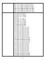
- 15 -
•Typ. 18±1.5dBm @ MCS6 40 MHz
•Typ. 18±1.5dBm @ MCS7 40 MHz
•Typ. 23±1.5dBm @ MCS8 40 MHz
•Typ. 20±1.5dBm @ MCS9 40 MHz
•Typ. 20±1.5dBm @ MCS10 40 MHz
•Typ. 20±1.5dBm @ MCS11 40 MHz
•Typ. 19±1.5dBm @ MCS12 40 MHz
•Typ. 19±1.5dBm @ MCS13 40 MHz
•Typ. 18±1.5dBm @ MCS14 40 MHz
•Typ. 18±1.5dBm @ MCS15 40 MHz
RX Sensitivity
802.11b:
• -93 dBm @ 1 Mbps
• -93 dBm @ 2 Mbps
• -93 dBm @ 5.5 Mbps
• -88 dBm @ 11 Mbps
802.11g:
• -88 dBm @ 6 Mbps
• -86 dBm @ 9 Mbps
• -85 dBm @ 12 Mbps
• -85 dBm @ 18 Mbps
• -85 dBm @ 24 Mbps
• -82 dBm @ 36 Mbps
• -78 dBm @ 48 Mbps
• -74 dBm @ 54 Mbps
802.11n (2.4 GHz):
• -89 dBm @ MCS0 20 MHz
• -85 dBm @ MCS1 20 MHz
• -85 dBm @ MCS2 20 MHz
• -82 dBm @ MCS3 20 MHz
• -78 dBm @ MCS4 20 MHz
• -74 dBm @ MCS5 20 MHz
• -72 dBm @ MCS6 20 MHz
• -70 dBm @ MCS7 20 MHz
• -95 dBm @ MCS8 20 MHz
• -90 dBm @ MCS9 20 MHz
• -87 dBm @ MCS10 20 MHz
• -83 dBm @ MCS11 20 MHz
• -80 dBm @ MCS12 20 MHz
• -74 dBm @ MCS13 20 MHz
• -71 dBm @ MCS14 20 MHz
• -69 dBm @ MCS15 20 MHz
• -87 dBm @ MCS0 40 MHz
• -83 dBm @ MCS1 40 MHz
• -83 dBm @ MCS2 40 MHz
• -80 dBm @ MCS3 40 MHz
• -76 dBm @ MCS4 40 MHz
• -73 dBm @ MCS5 40 MHz
• -69 dBm @ MCS6 40 MHz
• -67 dBm @ MCS7 40 MHz
• -93 dBm @ MCS8 40 MHz
• -88 dBm @ MCS9 40 MHz
• -85 dBm @ MCS10 40 MHz
• -82 dBm @ MCS11 40 MHz
• -78 dBm @ MCS12 40 MHz
• -73 dBm @ MCS13 40 MHz

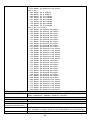
- 16 -
• -69 dBm @ MCS14 40 MHz
• -67 dBm @ MCS15 40 MHz
802.11a:
• -90 dBm @ 6 Mbps
• -88 dBm @ 9 Mbps
• -88 dBm @ 12 Mbps
• -85 dBm @ 18 Mbps
• -81 dBm @ 24 Mbps
• -78 dBm @ 36 Mbps
• -74 dBm @ 48 Mbps
• -74 dBm @ 54 Mbps
802.11n (5 GHz):
• -88 dBm @ MCS0 20 MHz
• -85 dBm @ MCS1 20 MHz
• -82 dBm @ MCS2 20 MHz
• -79 dBm @ MCS3 20 MHz
• -76 dBm @ MCS4 20 MHz
• -71 dBm @ MCS5 20 MHz
• -70 dBm @ MCS6 20 MHz
• -69 dBm @ MCS7 20 MHz
• -95 dBm @ MCS8 20 MHz
• -91 dBm @ MCS9 20 MHz
• -87 dBm @ MCS10 20 MHz
• -80 dBm @ MCS11 20 MHz
• -78 dBm @ MCS12 20 MHz
• -74 dBm @ MCS13 20 MHz
• -72 dBm @ MCS14 20 MHz
• -71 dBm @ MCS15 20 MHz
• -84 dBm @ MCS0 40 MHz
• -81 dBm @ MCS1 40 MHz
• -77 dBm @ MCS2 40 MHz
• -75 dBm @ MCS3 40 MHz
• -71 dBm @ MCS4 40 MHz
• -67 dBm @ MCS5 40 MHz
• -64 dBm @ MCS6 40 MHz
• -63 dBm @ MCS7 40 MHz
• -90 dBm @ MCS8 40 MHz
• -85 dBm @ MCS9 40 MHz
• -82 dBm @ MCS10 40 MHz
• -81 dBm @ MCS11 40 MHz
• -77 dBm @ MCS12 40 MHz
• -73 dBm @ MCS13 40 MHz
• -71 dBm @ MCS14 40 MHz
• -68 dBm @ MCS15 40 MHz
Protocol Support
General Protocols
Proxy ARP, DNS, HTTP, HTTPS, IP, ICMP, SNTP, TCP,
UDP, RADIUS, SNMP, PPPoE, DHCP
Interface
AP-only Protocols
ARP, BOOTP, DHCP
Interface
Connector for
External Antennas
QMA (female)
M12 Ports
1, 10/100/1000BaseT(X) auto negotiation speed,
F/H duplex mode, and auto MDI/MDI-X connection
Console Port
RS-232 (RJ45-type)

- 17 -
LED Indicators
PWR1, PWR2, PoE, FAULT, STATE, signal strength,
CLIENT MODE, WLAN, LAN
Alarm Contact
1 relay output with current carrying capacity of 1 A
@ 24 VDC
Digital Inputs 2 electrically isolated inputs
• +13 to +30 V for state “1”
• +3 to -30 V for state “0”
• Max. input current: 8 mA
Physical Characteristics
Housing
Metal, providing IP30 protection
Weight
850 g (1.87 lb)
Dimensions
52.9 x 151.9 x 127.4 mm (2.08 x 5.98 x 5.02 in)
Installation
DIN-rail mounting (standard), wall mounting
(optional kit)
Environmental Limits
Operating
Temperature
Standard Models: -25 to 60°C (-13 to 140°F)
Wide Temp. Models: -40 to 75°C (-40 to 167°F)
Storage
Temperature
-40 to 85°C (-40 to 185°F)
Ambient Relative
Humidity
5% to 95% (non-condensing)
Power Requirements
Input Voltage
12 to 48 VDC, redundant dual DC power inputs or 48
VDC Power-over-Ethernet (IEEE 802.3af compliant)
Input Current
12 V / 0.67 A @ 12 VDC, to 0.17 A @48 VDC, 25°C
Connector
10-pin removable terminal block
Power
Consumption
12 to 48 VDC, 670 mA
Reverse Polarity
Protection
Present
Standards and Certifications
Safety
EN 60950-1(LVD), UL 60950-1, IEC 60950-1(CB)
EMC
EN 55032/24
EMI
CISPR 32, FCC Part 15B Class B
EMI IEC 61000-4-2 ESD: Contact: 8 kV; Air: 15 kV
IEC 61000-4-3 RS: 80 MHz to 1 GHz: 20 V/m
IEC 61000-4-4 EFT: Power: 2 kV; Signal: 2 kV
IEC 61000-4-5 Surge: Power: 2 kV; Signal: 2 kV
IEC 61000-4-6 CS: 10 V
IEC 61000-4-8
Radio
EU: EN 300 328, EN 301 893
US: FCC ID SLE-WAPN008
JP: TELEC
Singapore: IDA*
Rail Traffic
EN 50155**, EN 50121-1/4, EN 45545-2
**
Complies with a portion of EN 50155 specifications.
Note: Please check Moxa’s website for the most up-to-date certification status.
*

- 18 -
MTBF (mean time between failures)
Time
742,649 hrs
Standard
Telcordia SR332
Warranty
Warranty Period
5 years
Details
See www.moxa.com/support/warranty.aspx
ATTENTION
The
AWK-3131A-M12-RCC is NOT
a portable mobile device and
should be located at least 20 cm away from the
human body.
The
AWK-3131A-M12-RCC is NOT designed for the general
public. To deploy
AWK-3131A-M12-
RCCs and establish a wireless
network safely, a well
-trained technician is required for
installation.
ATTENTION
Use the an
tennas correctly: The 2.4 GHz antennas are needed
when the
AWK-3131A-M12-RCC operates in IEEE 802.11b/g/n.
The 5 GHz antennas are needed for IEEE
802.11a/n. Make sure
your antenna installation is within a safety area, which is covered
by a lightning protection or surge arrest system.
-
 1
1
-
 2
2
-
 3
3
-
 4
4
-
 5
5
-
 6
6
-
 7
7
-
 8
8
-
 9
9
-
 10
10
-
 11
11
-
 12
12
-
 13
13
-
 14
14
-
 15
15
-
 16
16
-
 17
17
-
 18
18


Moxa Technologies AWK-3131A-RCC Series Quick Install Guide
- Type
- Quick Install Guide
- This manual is also suitable for
Ask a question and I''ll find the answer in the document
Finding information in a document is now easier with AI
Related papers
-
 Moxa Technologies AWK-3121-EU-T Installation guide
-
 Moxa Technologies AWK-3131A-M12-RTG Quick Install Guide
-
 Moxa Technologies AWK-3131A-RTG Series Quick Install Guide
-
 Moxa Technologies AirWorks AWK-1200-AP User manual
-
 Moxa Technologies Network Hardware MOXA AirWorks User manual
-
 Moxa Technologies AWK-4131 Hardware Installation Manual
-
Moxa Technologies AirWorks AWK-3191 User manual
-
 Moxa Technologies AirWorks AWK-5222 User manual
-
 Moxa Technologies AirWorks AWK-1131A User manual
-
 Moxa Technologies AirWorks AWK-3121-M12-RTG Quick Installation Manual


Other documents
-
Moxa AWK-3131A-RCC Series User manual
-
-
-
-
-
-
-
-
-
Moxa AWK-1121 Installation guide