Reznor AB industrial air curtains Operating instructions

Type
Operating instructions

Reznor AB industrial air curtains prevent the influx of cold air, draughts, and dust through door openings, maintaining a comfortable indoor climate. Ideal for large factory and warehouse doors, they create an air barrier with adjustable louvres for precise airflow direction. With multiple mounting options, these air curtains can be used singly or bolted together for wider openings, and are suitable for both natural and propane gas types.

Reznor AB industrial air curtains prevent the influx of cold air, draughts, and dust through door openings, maintaining a comfortable indoor climate. Ideal for large factory and warehouse doors, they create an air barrier with adjustable louvres for precise airflow direction. With multiple mounting options, these air curtains can be used singly or bolted together for wider openings, and are suitable for both natural and propane gas types.

Doc No. 702111 Page of 28
INDEX Section
General Information ------------------------------------------------------------ 1
Dimensions ------------------------------------------------------------------------ 2
Technical Specifications -------------------------------------------------------- 3
Installation Details --------------------------------------------------------------- 4
Wiring Details -------------------------------------------------------------------- 5
Servicing -------------------------------------------------------------------------- 6
Parts Replacement -------------------------------------------------------------- 7
Spare Parts ------------------------------------------------------------------------ 8
Fault Finding ---------------------------------------------------------------------- 9
User Instructions ---------------------------------------------------------------- 10
Part No. 702111
WARNINGS
1 This appliance must only be installed by a competent person in accordance with the requirements of
the Codes of Practice or the rules in force.
2 All external wiring MUST comply with the current IEE wiring regulations.
3 Warning this appliance must be earthed.
AB RANGE
GAS FIRED AIR CURTAIN
INSTALLATION AND OPERATING MANUAL
Doc No. 702111 Page 2 of 28
1. General Information.
Welcome to the new AB Reznor gas fired air
curtain models. Local regulations may vary in
the country of use and it is the installers
responsibility to ensure that such regulations are
satisfied.
All installation, assembly, commissioning and
service procedures must be carried out by
suitably qualified competent persons to the
statutory regulations in the country of use.
These instructions refer to products for use in
GB and the IE.
These air curtains are suitable for indoor use
only, and designed to operate at an ambient
temperature between –15°C and 30°C.
When installing, commissioning and servicing is
undertaken on the gas fired air curtains spec-
ified in these instructions, due care and atten-
tion is required to ensure that working at height
regulations are adhered to at the mounting
heights specified.
All dimensions shown are in mm unless
otherwise stated.
The manufacturer reserves the right to alter
specifications without prior notice.
PLEASE READ this document prior to
installation to familiarise yourself with the
components and tools you require at the
various stages.
The primary reason for installing gas fired air
curtains is to prevent the influx of cold outside
air through a door opening into a heated area.
Typical applications include large despatch bay
doors in factories and warehouses, and internal
doors between areas of different temperatures.
Wider door openings can be accommodated by
bolting two or more units together.
Air curtains control the internal climate by
emitting an air stream with enough velocity to
meet the floor so creating an air barrier in the
door area. To prevent the ingress of outside
draughts, the discharge louvre is angled
outwards, so that the air leaving the building
meets the wind trying to enter, thus deflecting it.
(See diagrams below).
Reznor gas fired air curtains provide uniform air
distribution across the full width of the door,
keeping heated or conditioned air inside the
building and stopping the ingress of cold air,
draughts, and dust.
This manual provides detailed information on
the installation of Reznor gas fired air curtains. It
is essential that these products are installed in
accordance with these manufacturers
instructions.
Without air curtain
With air curtain
Pattern of airflow
Doc No. 702111 Page 3 of 28
2. Dimensions.
Model A
mm
B
mm
C
mm
D
mm
E
mm
F
mm
G
mm
Weight
(kg)
AB 175 1750 950 457 700 700 125 1710 185
AB 225 2250 950 457 700 700 125 2210 230
Diagram 1: Dimensions
FRONT VIEW
PLAN VIEW
R/H VIEW
Doc No. 702111 Page 4 of 28
3. Technical Specifications.
Air curtain model ABxxxx
AB 225N AB 175N AB 225N AB 175N AB 225P AB 175P
Gas type
Natural gas G20 (I
2H
) Natural gas G25 (I
2L
) Propane G31 (I
3P
)
Gas connection
½ ¨ BSP external thread
Max supply pressure (mbar)
25 30 45
Min supply pressure (mbar)
17 20 25
Nominal pressure (mbar)
20 25 37
Gross heat input (kW)
66 49 66 49 65 49
Nett heat input (kW)
59.4 44.1 59.4 44.1 60.2 45.4
Gross heat output (kW)
60.1 44.6 60.1 44.6 59.2 44.6
Nett heat output (kW)
54.0 40.1 54.0 40.1 54.8 41.3
Gas flow rate (m³/hr)
6.3 4.7 7.4 5.4 - -
Gas flow rate (l/hr)
- - - - 9.4 7.0
No. of injectors
5
Injector size (mm)
Ø3.3 Ø2.9 Ø3.3 Ø2.9 Ø1.85 Ø1.65
Injector pressure (mbar)
7.5 7.0 10 10 25 25
Flue nominal bore (mm)
130
I/D fan
Voltage
230V 1 Ph 50 Hz
Power rating
100W
Current
0.5A (FLC)
Air distribution fans
Type
Centrifugal (with integral thermal trip)
Speeds
2
No. of fans
4 3 4 3 4 3
Maximum air volume
9600m
3
/hr (AB 175) 12800m
3
/hr (AB 225)
Voltage
230V 1PH 50Hz
Power rating (per fan)
1140 W
Current (per fan)
5.2A (FLC)
Start current (per fan)
12A
Model AB175 AB225
AB350= X 2
AB400= X 1 X 1
AB450= X 2
AB525= X 3
AB575= X 2 X 1
AB625= X 1 X 2
AB675= X 3
Constitution
WARNING:
THIS AIR CURTAIN SHOULD NOT BE
INSTALLED WHERE THERE IS A
CORROSIVE ATMOSPHERE.
Doc No. 702111 Page 5 of 28
4. Installation Details.
4.1.1
Each single air curtain should be supported by
cantilever brackets (not supplied) then fixed
back to the building structure by bolting directly
using suitable support brackets, or by
suspending from above using suitable
steelwork. (See diagram 3, page 6).
4.1.2
Multiple air curtains should be bolted together
using 3 off M10 set pins, nuts and washers fitted
through the holes provided in the mounting
brackets, then suitable support channels (not
supplied) must be fixed on top of the factory
fitted brackets along the full length of the
assembled air curtains to spread the load.
The assembly can now be fixed back to the
building structure by bolting directly using
suitable support brackets, or suspending from
above using steelwork. (See diagram 4 page 6).
If required, the support channel may be
extended slightly past the ends of the air
curtains to aid fixing.
Note: Where multiple air curtains are fitted
above up and over doors or where central
support is inappropriate, the support channel
should be replaced with channels of a greater
cross section to prevent the assembly from
bending.
It may be necessary to adjust the position of the
air outlet louvres to provide the correct airflow
across the door opening. This can be done by
first loosening the four locking pins located two
at each end of the louvres (arrowed, Fig. A),
then loosening the intermediate locking Allen
pins (arrowed, Fig. B). The louvres can now be
moved to the desired position and the locking
pins re-tightened.
NOTE: The AB 225 model has two pairs of
intermediate locking Allen pins, whereas the AB
175 model only has one pair.
Fig. B
Fig. A
Locking pins
Locking Allen pins
Gap to be kept to a minimum
1.8m minimum
Bottom of air curtain
to be level with top of
door opening
Health and Safety
Airbloc air curtains must be installed in
accordance with the relevant provisions of the
Gas Safety (Installations and Use) Regulations
1998. Due account should also be taken of any
obligations arising from the Health and Safety at
Work Act 1974 or relevant codes of practice. In
addition the installation must be carried out in
accordance with the current IEE wiring
regulations (BS 7671), BS 6896 (Industrial &
Commercial) and any other relevant British
Standards and Codes of Practice by a qualified
installer. Isolate all electrical supplies to the
heater & control panel before proceeding.
For your own safety we recommend the use of
personal protective equipment when handling
this air curtain.
Before installation, check that the local
distribution conditions, nature of gas and
pressure, and the current state of adjustment of
the appliance are compatible.
Reznor gas fired air curtains are supplied with
mounting brackets pre-fitted, either as single
units, or in multiples, which can be bolted
together to suit various door widths.
The minimum mounting height is 1.8 metres
(see diagram 2 below).
4.1 Mounting.
Diagram 2.
Doc No. 702111 Page 6 of 28
Diagram 3: Mounting method (single air cur-
FRONT VIEW (SINGLE AIR CURTAIN)
Diagram 4: Support channel (multiple air curtains)
4.2 Flueing.
The gas fired air curtain must be installed with a
fixed flue. The fan is fitted with a 130mm
diameter female outlet. (Flue and fittings can be
supplied by the manufacturer).
The flue pipe should be adequately supported at
regular intervals from the building structure and
terminated externally with a British Gas tested
and certified GC1 terminal.
The maximum flue length is 7m and the max-
imum number of bends is two on individ-
ually flued appliances. The flue may be installed
vertically or horizontally, noting that horizontal
flues MUST be terminated vertically. (See dia-
grams 5, 6 and 7 on pages 8 and 9).
4. Installation Details cont.
4.3 Ventilation requirements.
In buildings having an air change rate of less
than 0.5 per hour, additional mechanical or nat-
ural ventilation is required. For detailed infor-
mation please see BS6230 section 5.2.2.2.1.1.
4.3.1 Mechanical ventilation.
Should be installed to meet a minimum of 0.5 air
changes per hour using appropriately sized fans
interlocked with the heaters.
4.3.2 Natural ventilation.
Low level ventilation openings with a free area
of at least 2cm
2
/kW shall be provided. See
section 5.2.2.2.1.2.
Cantilever brackets
(not supplied)
Factory fitted
mounting brackets
Typical support channels
PLAN VIEW (TWIN AIR CURTAINS)
Air curtain 1 Air curtain 2
Factory fitted brackets
Support points
Doc No. 702111 Page 7 of 28
4. Installation Details cont.
Model AB 225 AB 175
Gas type
Natural gas (G20) Propane (G31) Natural gas (G20) Propane (G31)
Mass flow rate of
Flue gases (kg/s)
0.0340 0.0332 0.0242 0.0283
Flue gas temperature
@ flue outlet (ºC)
162 173 172.5 182
Flue pressure (Pa)
positive
55 49
Flue technical details.
Component Internal size (mm) Resistance factor (Ke)
Pipe 130 0.25 per metre
90º bend 130 0.5 per fitting
135º bend 130 0.25 per fitting
Terminal 130 GC1 0.25 per fitting
Method for calculating equivalent flue resistance.
Inlet resistance of flue (Ki) Outlet resistance of flue (Ko)
130 mm spigot 1.0 130 mm flue 1.0
The formula for calculating the equivalent flue
size is as follows:
H
e
= H
a
x (K
i
+ K
o
)
e
(K
i
+ K
o
)
a
- K
e
H
a
+ ΣK
Where:
H
e
is the height of the equivalent flue.
H
a
is the vertical height of the actual or
proposed flue measured from the flue spigot.
K
i
is the inlet resistance of the flue.
K
o
is the outlet resistance of the flue.
Subscript '
e
' refers to the equivalent flue
diameter. Subscript '
a
' refers to the actual or
proposed flue diameter.
K
e
is the resistance per unit length of the
equivalent flue.
ΣK is the resistance (other than the inlet and
outlet resistances) of the actual or proposed
flue.
Note: K
i
and K
o
are obtained from the table
above.
Inlet resistance of actual flue 1
Outlet resistance of actual flue 1
Inlet resistance of equivalent flue 1
Outlet resistance of equivalent flue 1
The vertical height of the actual or
proposed flue measured from the
flue spigot
7
Other resistances of actual flue:
Terminal (1) 0.25
90º bend (0) 0
135º bend (0) 0
Flue pipe 1.75
H
e =
6.22
Example (125mm diameter):
WARNING:
THIS AIR CURTAIN SHOULD NO BE
INSTALLED WHERE THERE IS A
CORROSIVE ATMOSPHERE.
Doc No. 702111 Page 8 of 28
4. Installation Details cont.
Diagram 5: Typical vertical flue arrangement
FRONT VIEW
Diagram 6: Typical horizontal flue arrange-
ment
Ventilation requirements are detailed in
section 4.3.
Fan to flue adapter
(supplied)
7.0m max
GC1 terminal
1m min
600mm
minimum
GC1 terminal
Fan to flue adapter
(supplied)
600mm
minimum
I/D fan rotated
through 90º
SIDE VIEW
Doc No. 702111 Page 9 of 28
4. Installation Details cont.
Diagram 7: Typical horizontal flue arrange-
ment
GC1 terminal
90 deg. bend
(not supplied)
Alternative position
for 90 deg. bend
PLAN VIEW
Fan to flue
adapter (supplied)
Flue passes through
mounting bracket(s)
Doc No. 702111 Page 10 of 28
4. Installation Details cont.
5. Wiring Details.
Diagram 7: Burner control wiring
Before fitting a horizontal flue, it will be
necessary to rotate the I/D fan through 90º on
it`s mounting bracket to enable the flue to be
routed to the rear of the air curtain as shown in
diagram 6.
Removal and refitting of the I/D fan is described
in section 8 of this manual, parts replacement
(Fig.18).
Note:1:The maximum permissible
horizontal flue length should be calculated
using the formula for equivalent flue sizes
shown on the previous page.
2: When the horizontal flue is to pass
through a wall constructed of combustible
material, a suitable approved fireproof sleeve
should be fitted prior to installing the flue pipe.
Doc No. 702111 Page 11 of 28
5. Wiring Details cont.
5.1 Burner controls
The burner controls are mounted in the burner
control cubicle which is an integral part of the air
curtain casing and are accessible by opening a
hinged lid on the right hand side of the air
curtain (see Figs. 4 and 5 in section 8 of this
manual for details). The controls accessible in
the cubicle are: gas solenoid valve, ignition
controller, air pressure switch, flame probe,
ignition electrode, reset switch, red and amber
neon lamps, plus associated wiring harness. For
details see burner wiring diagram in section 5,
page 9.
5.2 Control panel.
The electrical control panel incorporates the
facility to interlock with the door opening
mechanism and automatically switch the air
curtain between high/low speed as the door is
opened and closed. A pair of volt free auxiliary
contacts are required on the door open/close
contactor which closes as the door opens. If this
is not available then a suitably positioned limit
switch and striker plate will need to be fitted to
the door.
The panel incorporates an auto/off/manual
selector switch, which, when in 'auto' mode
operates the air curtain in low speed via an
external room thermostat provided the door is
the down position. In the door up position the air
curtain operates in high speed and overrides the
room thermostat The 'manual' position overrides
the door interlock and thermostat, and the 'off '
position turns the air curtain off.
A cool/heat selector switch is also incorporated
which allows the air curtain to supply heated
air, or unheated ambient air.
The panel also contains a removable link on the
main terminal rail to allow the air curtain to be
switched on and off remotely via a BMS control
relay.
The panel may also be fitted with optional low
voltage (24V AC) relays for fire alarm/door
contact interlocks.
Regardless of the position of any of the above
switches, the main air fans must be running to
allow the burner to run.
5.3 Overheat protection.
In the event of any overheat condition there are
two thermal limit controls fitted inside the air
curtain. The controls are factory set and
non-adjustable. The self resetting (cycling)
control activates at 70ºC, and the manual reset
control at 96ºC. If either set point is reached, the
corresponding limit control will interrupt the
electrical power to the burner gas valve. The
burner will not relight until the limit control has
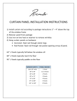
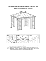
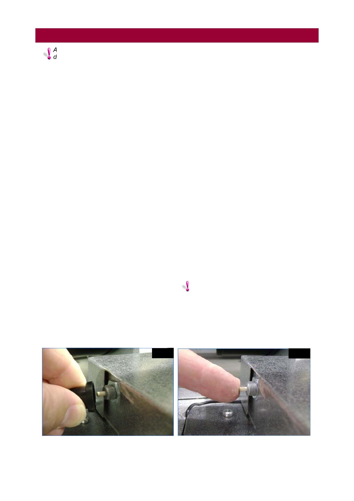
reset. The manual reset button is located on top
of the heater on the left hand side of the
thermostat cover and can be accessed after first
removing the dust cover. (See Figs. C and D).
These safety devices provide protection in the
event of an air distribution fan motor failure, or
lack of airflow due to restrictions. (For location
see section 8 Fig.29, and section 5 diagram 8,
burner controls wiring diagram).
Warning: never attempt to bypass the
thermal limit controls as hazardous
conditions could result.
Fig. C
Fig. D
A customer specific control panel wiring
diagram will be supplied with each air curtain
Doc No. 702111 Page 12 of 28
6. Servicing.
These appliances should be serviced annually by a competent person to ensure safe
and efficient operation. In exceptionally dusty or polluted conditions more frequent
servicing may be required. The manufacturer offers a maintenance service. Details
available on request. Isolate gas and electricity supplies before commencing any work.
Cross point
screwdriver
6.1 Tools Required.
The following tools and equipment are advisable
to complete the tasks laid out in this manual.
Suitable alternative tools may be used.
Small flat head
screwdriver
Allen key set
Adjustable
pipe wrench
Adjustable
spanner
10mm spanner
13mm spanner
Manometer
Soft
brush
6.2 Burner assembly.
The major components of the burner assembly
can be accessed by removing the two lid
retaining screws located on the right hand side
on top of the air curtain, and swinging the lid
downwards as shown in Figs 4 & 5 in section 8
of this manual. Section 8 also details the
removal of the major components.
6.2.1 Manifold/injectors.
Remove the manifold complete with injectors as
described in section 8. The manifold/injectors
should be examined for signs of debris and
cleaned if necessary by blowing compressed air
in the reverse direction to flow. Individual
injectors can be replaced if necessary.
6.2.2 Burners.
Access to the burners is achieved by first
removing the mounting plate carrying the
ignition sequence controller and pressure
switch, (see section 8). The access plate can
now be removed after unscrewing the four fixing
screws. The burners can now be examined and
cleaned using a soft brush, or by blowing
compressed air in the reverse direction to flow.
Individual burners can be replaced if necessary
by removing the two retaining screws.
6.2.3 Spark electrode .
Remove the spark electrode as described in
section 8 and examine. If it is in good order
check the electrode gap, this should be 3.5mm ±
0.5mm. Adjust the gap if necessary by carefully
bending the earth rod, then re-checking the
measurement.
6.2.4 Flame probe.
Remove the flame probe as described in section
8 and examine for signs of erosion. The probe
should be cleaned if necessary using a fine
grade emery paper.
6.3 I/D fan.
NOTE: Before removing the I/D fan it will
be necessary to remove the first flue
section after releasing it from the fan/flue adapt-
er. (See section 8 Fig.20 for details).
Disconnect and remove I/D fan as described in
section 8. Clean off any dust or deposits using a
soft brush paying particular attention to the
impeller. Also remove any dust or deposits from
the finger guard covering the secondary
(cooling) impeller, and the mesh aperture in the
motor cover. Check that the impeller is free to
rotate and that there is no play in the
bearings.
6.4 Emitter tubes.
6.4.1 External.
Brush away any dust on the exterior of the
emitter tubes after first removing the ten screws
retaining the mesh air inlet grille as shown in
Fig.0. overleaf
6.4.2 Internal.
To gain access first remove the five retaining
screws from the inspection cover as shown in
Fig.1 overleaf.
Doc No. 702111 Page 13 of 28
Remove the six flue box lid retaining nuts from
their captive studs as shown in Fig.2. then
remove lid taking care not to damage the
gasket.
Remove turbulators (5 off) as shown in Fig.3,
and clean off any dust or deposits with a soft
brush.
NOTE: The turbulators are fitted in the
emitter tube non-firing legs only. (See
Fig.4)
Clean out the emitter tubes using a suitable flue
brush/scraper fitted with flexible extension rods.
NOTE: To clean the firing legs of the
emitter tubes it is necessary to remove the
burners as described in section 6.2.2.
6.5 Air outlet louvres.
The air outlet louvres should be cleaned with a
soft brush. Check that the louvres are set to the
required angle.
6.6 Air distribution fans.
The air distribution fans can be accessed by
opening the fan lid as described in section 8.
Clean off any dust or deposits with a soft brush
paying particular attention to the impeller. Check
that the impeller spins freely, and that there is
no play in the fan bearings.
The fan(s) can be removed, if necessary, as
described in section 8.
NOTE: Following any servicing work it will
be necessary to re-commission the air
curtain (See section7).
6. Servicing cont.
Fig.1
Fig.2
Fig.3
Fig.4
Fig.0
Doc No. 702111 Page 14 of 28
7. Commissioning.
NOTE: If the air curtain will not start on initial
start up, the ignition controller may be in
lockout position and require resetting. This may
occur especially if the appliance has been on
stand-by for a prolonged period.
7.4 Air curtain lighting sequence
AB air curtains are fitted with automatic spark
ignition. When adequate airflow for combustion
is proven by an air proving switch, and a pre
-purge period has elapsed, the integral igniter
and gas control valve operate. The ignition
spark ignites the burner and the flame is detect-
ed by a flame ionisation rod sensor. If a burner
flame is not detected, then the ignition controller
proceeds to lockout and will require manually
resetting. Lockout is indicated by the illuminated
burner rocker switch on the burner housing, and
by a lockout lamp on the control panel, and can
be reset either by pressing the illuminated burn-
er rocker switch or the control panel lockout re-
set button.
NOTE: If the first lockout reset is not
successful, further investigation will be
required to ascertain the fault.
7.5 Burner gas pressure adjustment
The gas pressure is set for the required heat
input before the appliance leaves the factory,
normally, provided the gas supply to the air
curtain is in accordance with the supply
pressure described on the appliance data plate,
the operating pressure will not require
adjustment. To check the pressure, the following
procedure should be carried out:
This appliance must be commissioned by
a suitably qualified engineer
7.1 Gas connection
Only persons suitably qualified to work on gas
fired appliances may carry out commissioning
and testing. The whole of the gas service
installation including the meter must be
inspected, tested for gas soundness, and
purged in accordance with the current rules in
force.
WARNING: Never use a naked flame for
checking gas soundness.
7.2 Air curtain gas pipework
The gas soundness of the air heater pipework
has been checked prior to leaving the factory.
however during installation, connections may
have been loosened. Check the gas soundness
of the appliance pipework using suitable leak
detection fluid. If any leaks are found they must
be rectified immediately.
7.3 Check vacuum setting
7.3.1 Ensure that the gas and electrical supply
to the control panel is switched on. Ensure that
the control panel heat/cool selector switch is set
to the 'cool' position. The air curtain fans will
now start.
7.3.2 Remove the cap from the tee piece test
point (see Fig.4A) and connect a manometer.
7.3.3 Adjust flue damper (see Fig.4B) to achieve
the cold vacuum setting as shown in the table.
7.3.4 Ensure that the control panel heat/cool
selector switch is now set to the 'heat' position.
The air curtain fans will now start and the burner
will fire automatically. Allow the air curtain to
heat up for 15 minutes.
7.3.5 Adjust flue damper (see Fig4B) to achieve
the hot vacuum setting as shown in the table.
Fig.4A
Fig.4B
Doc No. 702111 Page 15 of 28
7. Commissioning cont.
7.5.1
Ascertain from section 3 (technical
specifications) of this document, and the
appliance data plate, the correct operating gas
pressure for the air curtain burner.
7.5.2
Turn the control panel cool/heat selector switch
to the 'cool' position.
7.5.3
Remove the screw from the burner pressure test
point of the gas control valve (see Fig. 5 ).
7.5.4
Connect a suitable manometer to the burner
pressure test point.
Turn the control panel cool/heat selector switch
to the 'heat' position, then wait for burner to light.
7.5.5
Observe the burner gas pressure reading on the
manometer and compare to the required
pressure.
7.5.6
If necessary adjust as follows:
First remove the plastic dust cover from the
regulator adjusting screw. Turn the regulator
adjusting screw anticlockwise to decrease gas
pressure, or clockwise to increase gas pressure.
(See Fig.6 ) After adjustment replace dust cover.
7.5.7
Set control panel heat/cool switch to the 'cool'
position to turn the burner OFF. Replace the test
point screw (if removed). Relight the burner and
test for gas soundness using suitable leak
detection fluid.
Fig.5
-
+
Fig.6
Gas flow
Doc No. 702111 Page 16 of 28
All servicing/maintenance work on this air
curtain should be carried out by suitably
qualified and Corgi registered engineer. Before
commencing any work please ensure that the
gas and electricity supplies are turned off.
Always test for gas soundness with a suitable
leak detection fluid.
8.0 Tools required.
8.1 Burner/control assembly.
The major components of the burner/control
assembly can be accessed by removing the two
lid retaining screws located on the right hand
side on top of the air curtain, and swinging the
lid downwards as shown in Figs 7 & 8.
8. Parts Replacement.
Allen key set Adjustable
pipe wrench
Adjustable
spanner
Cross point
screwdriver
10mm spanner
13mm spanner
Fig.8
8.1.1 Gas valve.
Remove electrical connectors as shown in Fig.9
Disconnect the mains gas pipe feeding the air
curtain complete with gas cock. Remove the two
strain relief plate screws (arrowed, Fig.10). The
pipe can only be removed downwards complete
with the gas valve, (see description and Figs. 11
and 12 overleaf).
Fig.7
Strain relief
plate screws
Fig.10
Fig.9
Doc No. 702111 Page 17 of 28
8. Parts Replacement cont.
Using a suitable pair of spanners release the
union on the outlet side of the gas valve as
shown in Fig. 11.
Remove the two mounting bracket screws as
shown in Fig.12.
The valve can now be withdrawn from the air
curtain, and the mounting bracket removed if
necessary
8.1.2 Gas manifold/injectors.
Follow previous steps describing removal of
valve to manifold pipe union. Remove the four
manifold retaining screws as shown in Fig.13.
The manifold can now be removed downwards
complete with injectors. Fig.14 shows the
manifold with injectors in isolation for clarity.
8.1.3 Air pressure switch.
Remove the silicon tubing from the rear
connection of the air pressure switch as shown
in Fig.15.
NOTE: only a single tube is fitted to the air
pressure switch on the negative pressure
side.
Remove the two retaining screws as shown in
Fig.16.
Fig.15
Fig.16
Fig.13
Mounting screws
Fig.12
Fig.14
Fig.11
Doc No. 702111 Page 18 of 28
8. Parts Replacement cont.
Lift the air pressure switch upwards from the
rear of the mounting plate then remove the three
female spade connectors as shown in Fig.17
then remove switch.
8.1.4 Ignition sequence controller.
Disconnect the multi-pin connectors from the
ignition controller as shown in Fig.18.
Remove the two fixing screws securing the
ignition controller to the mounting plate as
shown in Fig. 19. then remove controller.
8.1.5 I/D fan.
The I/D fan is mounted on top of the unit
towards the right hand side.
First remove the flue and the fan/flue adapter
from the fan outlet.
Disconnect the mains plug/socket feeding the
fan.
Remove the four 6mm screws (arrowed Fig. 20)
securing the fan to the air curtain flue outlet.
Remove the fan taking care not to damage the
gasket seal.
Fig.17
Fig.19
Fig.18
Fig.20
Securing screws
Doc No. 702111 Page 19 of 28
8.1.6 Flame probe.
Remove the flame probe cable spade connector
as shown in Fig.21.
Remove flame probe fixing screw as shown in
Fig.22.
Withdraw flame probe as shown in Fig.23.
8. Parts Replacement cont.
Fig.21
Fig.22
Fig.23
Fig.24
Fig.25
Fig.26
8.1.7 Spark electrode
Remove the HT cable spade connector from the
ignition sequence controller as shown in Fig.24.
Remove fixing screw as shown in Fig.25.
Withdraw spark electrode complete with HT
cable as shown in Fig.26.
Doc No. 702111 Page 20 of 28
8. Parts Replacement cont.
Remove the spade terminals from the manual
reset thermostat as shown in Fig. 30.
Remove the single retaining screw securing the
manual reset thermostat as shown in Fig.31.
Remove from location slot complete with bracket
as shown in Fig.32.
8.1.8 Overheat thermostats
Remove the two retaining screws securing the
thermostat access lid as shown in Fig.27.
Disconnect the spade terminals from the self
resetting thermostat as shown in Fig.28.
Remove the two retaining screws as shown as
shown in Fig.29. and remove.
Fig.27
Fig.28
Fig.29
Fig.30
Fig.31
Fig.32
  • Page 1 1
  • Page 2 2
  • Page 3 3
  • Page 4 4
  • Page 5 5
  • Page 6 6
  • Page 7 7
  • Page 8 8
  • Page 9 9
  • Page 10 10
  • Page 11 11
  • Page 12 12
  • Page 13 13
  • Page 14 14
  • Page 15 15
  • Page 16 16
  • Page 17 17
  • Page 18 18
  • Page 19 19
  • Page 20 20
  • Page 21 21
  • Page 22 22
  • Page 23 23
  • Page 24 24
  • Page 25 25
  • Page 26 26
  • Page 27 27
  • Page 28 28

Reznor AB industrial air curtains Operating instructions

Type
Operating instructions

Reznor AB industrial air curtains prevent the influx of cold air, draughts, and dust through door openings, maintaining a comfortable indoor climate. Ideal for large factory and warehouse doors, they create an air barrier with adjustable louvres for precise airflow direction. With multiple mounting options, these air curtains can be used singly or bolted together for wider openings, and are suitable for both natural and propane gas types.

Ask a question and I''ll find the answer in the document

Finding information in a document is now easier with AI