
© Midmark Corporation - 2001 Page 1 of 5
NOTES
• This plan may be placed on the floor in the de-
sired location and then used as a template for
punching center holes.
• The locations shown in this plan are suggestions
and are not meant to be restrictive in any way.
They may be altered to fit the situation or suit the
doctor’s preferences.
• If so equipped, the APC may be removed for
J-box and umbilical installation.
• The electrical and plumbing supply connectors in-
side the J-Box (Junction Box) must be installed by
an electrician and plumber in compliance with lo-
cal building codes.
• Midmark Corporation assumes no responsibility
for failure due to improper installation.
CAUTIONS
• Water and air valves to be located as to be readily
accessible for emergency shut-off. DO NOT
LOCATE VALVES UNDER APC UNIT if so
equipped.
• Be sure that connection box location DOES NOT
INTERFERE WITH CHAIR MOVEMENT.
• Water pressure to be a minimum of 30 PSI (207
Kpa) but NOT TO EXCEED 50 PSI (345 Kpa)
MAXIMUM.
• Air pressure to be 80 PSIG (552 Kpa) and NOT
TO EXCEED 100 PSIG (689 Kpa) MAXIMUM.
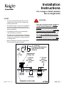
1" (2.5 cm)
(max.)
3/4" (1.9 cm)
(min.)
AIR and
WATER
VACUUM
WASTE
FINISHED FLOOR LEVEL
1/2"
(1.3 cm)
16" (40.6 cm)
Recommended Location
from Center of Chair
Rotation
1" (2.5 cm)
(max.)
3/4" (1.9 cm)
(min.)
Compression
Fitting Valve
Installation
Instructions
For a Large or Small Junction
Box on Knight Units

© Midmark Corporation - 2001 Page 2 of 5
UTILITY SPECIFICATIONS
WATER
1/2" pipe terminating with a 1/2" pipe up 3/4" (1.9 cm) to 1" (2.5 cm) from
the finished surface as near to the connection box as possible.
Flush all debris from the lines before installation.
Water pressure to be a minimum 30 psi (207 kPa) and not to exceed a
maximum 50 psi (345 kPa).
AIR
1/2" pipe terminating with a 1/2" pipe up 3/4" (1.9 cm) to 1" (2.5 cm) from
the finished surface as near to the connection box as possible.
Flush all debris from the lines before installation.
Air pressure to be minimum 80 PSIG (552 kPa) and not to exceed a
maximum 100 PSIG (689 Kpa).
For maximum life of unit, air supply must be clean and dry.
It is recommended that a moisture separator and filter be installed as near
to the connection box as possible and be accessible for periodic cleaning.
ELECTRICAL SUPPLY
Three (3) conductor #14 AWG cable on a 15 amp fused circuit to terminate
inside a 4" (10.1 cm) x 4" (10.1 cm) jiffy box (not supplied) in location
shown.
If installing 115 VAC receptacle:
A right angle power plug is supplied.
If installing a 230 VAC receptacle:
An appropriate style power plug rated for 250 VAC, 15 amps (not supplied)
is required .
VACUUM
Terminate with 5/8" OD tube 3/4" (1.9 cm) to 1" ( 2.5 cm) above the
finished floor.
Install line according to vacuum system manufacturer’s specifications.
AUXILIARY WIRING
Low voltage.
“For class 2 circuits only”.
Install in compliance with all prevailing codes.
WASTE
Required for the Gravity Drain Cuspidor.
Not less than 1 1/2" ID pipe from down pipe to trap decreasing to 3/4" pipe
from trap to connection box.
Terminate with 3/4" O.D. pipe 3/4" (1.9 cm) to 1" (2.5 cm) above finish floor.
Install trap in line and vent to conform with local codes.
003-1190-01 Rev.F (8/12)
Midmark Corporation
60 Vista Drive
P.O. Box 286
Versailles, Ohio 45380-0286
1-800-MIDMARK
Fax 877-249-1793
midmark.com

© Midmark Corporation - 2001 Page 3 of 5
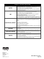
ELECTRICAL
BOX
4" x 4"
BOX FOR
POWER
SUPPLY
(not
supplied)
AIR
WATER
VACUUM
WASTE
TUBING FOR
OPTIONS
UMBILICAL
FOOT CONTROL
TUBING INLET AIR
(5/16" Clear w/
Black Dash)
1/8" RED TUBE
PILOT AIR
MASTER VALVE
1/8" PURPLE TUBE
NON-CONTROLLED
AIR MASTER VALVE
1/4" BLUE TUBE
CUSPIDOR
(Optional)
1/8" ORANGE TUBE
COOLANT WATER
PILOT AIR
1/4" or 5/16"
CLEAR TUBE
DRIVE AIR OUT
1/8" YELLOW TUBE
FOR SYRINGE AIR
1/8" YELLOW or
WHITE TUBE
(Tagged w/ "C")
FOR CUSPIDOR
(Optional)
1/8" BROWN TUBE
AIR TO DISTILLED
WATER BOTTLE
1/8" BROWN TUBE
1/8" RED TUBE
Blue
Green
Clear
White
AIR REGULATOR
FOR DISTILLED
WATER BOTTLE
1/4" CLEAR TUBE
FOR AIR QUICK
CONNECT (Optional)
5/16" CLEAR TUBE
(
w/ BLACK DASH
)
TO FOOT CONTROL
TO FOOT
CONTROL
5/16"
CLEAR
TUBE
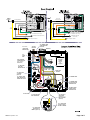
Air
Regulator
5/16" Clear
80 PSI
1/8 Yellow
80
PSI
1/8 Orange
To Handpiece Coolant Air (1/8 Green)
Clear
Throttle
Valve
Wet / Dry
Toggle
5/16" Clear
(w/ Black Dash)
1/8
Yellow
To Pilot Air for Coolant Water (1/8 Orange)
1/8 Green
Air to Syringe & Cuspidor
Filter / Regulated Air
80 PSI
80
PSI
Foot Control
Clear
1/8 Orange
5/16" Clear
To Handpiece Drive Air
(5/16" Clear)
1/8 Green
1/8
Green
5/16"
Clear
1/8 OR
1/8
GN
5/16"
Clear
w/ Dash
1/8
BN
(Chip Air)
1/4 Grey (Plain)
1/4 Clear
80 PSI
To Handpiece Drive Air (1/4 Clear)
1/8 Yellow
80
PSI
1/8 Orange
To Handpiece Coolant Air (1/8 Green)
Clear
1/8 Grey
Throttle
Valve
Wet / Dry
Toggle
Tubing
Layout
1/8 Grey (above 1/4 ribbed)
1/4 Grey (Ribbed)
1/8
Yellow
To Pilot Air for Coolant Water (1/8 Orange)
1/8 Green
Air to Syringe & Cuspidor
Filter / Regulated Air
Air
Regulator
80 PSI
80
PSI
(Rib)
Foot Control
1/8 Grey
Clear

© Midmark Corporation - 2001 Page 4 of 5
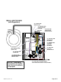
WATER
AIR
WATER
OUT IN
1/4" BLUE TUBE / CUSPIDOR WATER
UNFILTERED AND UNREGULATED (OPTIONAL)
1/8" RED TUBE
PILOT AIR
MASTER VALVE
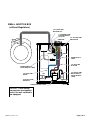
SMALL JUNCTION BOX
(with Regulators)
NOTICE: These tubing
connections are required
only if the unit installed is
so equipped.
UMBILICAL
1/8" ORANGE TUBE
COOLANT WATER
PILOT AIR
1/4" CLEAR TUBE
DRIVE AIR OUT
VACUUM
WASTE
1/4" YELLOW TUBE
ASST WATER
(OPTIONAL)
1/8" BROWN TUBE
CUSPIDOR
PILOT AIR
(OPTIONAL)
1/8" BLUE TUBE
COOLANT AND
SYRINGE WATER
FOOT CONTROL INLET
(TUBE w/ RIB)
1/8" YELLOW TUBE
SYRINGE AIR
1/8" PURPLE TUBE
NON-CONTROLLED AIR
MASTER VALVE

© Midmark Corporation - 2001 Page 5 of 5
AIR
WATER
WATER
OUT IN
UMBILICAL
1/8" ORANGE TUBE
COOLANT WATER
PILOT AIR
1/4" CLEAR TUBE
DRIVE AIR OUT
1/4" YELLOW TUBE
DRIVE AIR IN
VACUUM WASTE
POWER UMBILICAL
(SUPPLIED WITH J-BOX)
1/4" BLUE TUBE
WATER
3/8" BLACK TUBE
AIR SUPPLY
3/8" BLACK TUBE
WATER SUPPLY
(SUPPLIED WITH
J-BOX)
WATER SHUT OFF VALVE
1/8" RED TUBE
PILOT AIR
POWER SUPPLY
CABLE
SMALL JUNCTION BOX
(without Regulators)
NOTICE: These tubing
connections are required
only if the unit installed is
so equipped.
-
 1
1
-
 2
2
-
 3
3
-
 4
4
-
 5
5


Midmark Asepsis 21® Systems Installation guide
- Type
- Installation guide
- This manual is also suitable for
Ask a question and I''ll find the answer in the document
Finding information in a document is now easier with AI
Related papers
-
Midmark International (Whip) Delivery User guide
-
Midmark Procenter Systems Product information
-
-
Midmark Asepsis 21® Systems Installation guide
-
-
-
-
-
-
Other documents
-
Belmont EDS Over-The-Patient Delivery Installation guide
-
-
TPC MSP3550 User manual
-
 DentalEZ J-Chair J-3 Installation, Operation & Care Manual
-
Acclaim Lighting ISO13405 User manual
-
-
B.A. International BA720K User manual
-
-
Aseptico ADU-08 Owner's manual
-
