Page is loading ...

ICE/BEVERAGE DISPENSERS
MODELS:TJ45--A,TJ45--AB
TJ90--A,TJ90--AB,
TJ90--ABC
Operator’sManual
WITH AUTOMATIC ICEFILLING FROMA REMOTEICEMAKERSOURCE
PRINTEDIN U.S.A
âREMCORINC:
PartNo.90632
Revision H
Revised March 21,1996
THISDOCUMENTCONTAINSIMPORTANTINFORMATION
ThisManualmustbe read and understood beforeinstalling oroperating thisequipment

i90632
TABLEOFCONTENTS
Page
SAFETY PRECAUTIONS1...................................................
DESCRIPTION2............................................................
INSTALLATIONINSTRUCTIONS3............................................
SINKDRAINASSEMBLY3...............................................
CLEANING INSTRUCTIONS4................................................
DISPENSER4..........................................................
COLDPLATEWHEN REQUIRED4.......................................
BEVERAGE SYSTEM(WHEN REQUIRED)4..............................
OPERATINGINSTRUCTIONS5..........................................
SERVICEAND MAINTENANCE6.............................................
ADJUSTMENTS6.......................................................
TROUBLESHOOTING GUIDE7...............................................
BLOWNFUSE OR CIRCUITBREAKER7..................................
GATEDOES NOTOPEN.AGITATOR DOES NOT TURN.7..................
GATEDOES NOTOPENORIS SLUGGISH.AGITATORTURNS.7...........
GATEOPENS.AGITATOR DOES NOT TURN.7............................
ICEDISPENSES CONTINUOUSLY.7......................................
SLUSHYICE.WATERIN HOPPER7......................................
ICE SOLIDIFIEDIN HOPPER,ORICE ATREAR CORNERONLY.7...........
NOICEIN HOPPER7...................................................
ICE PACKEDIN HOPPER.7..............................................
BEVERAGES DONOTDISPENSE 7......................................
BEVERAGES TOSWEET.7..............................................
BEVERAGES NOTSWEETENOUGH.7...................................
BEVERAGES NOTCOLD(UNITSWITHBUILT-IN COLDPLATE)7...........
PARTSLIST18..............................................................
WARRANTY20..............................................................
LISTOF FIGURES
FIGURE1.SINKDRAINASSEMBLY3.....................................
FIGURE2.GATERESTRICTORPLATE6..................................
FIGURE3.MOUNTINGTEMPLATE8.....................................
FIGURE4.TYPICALPOST-MIX BEVERAGE SYSTEM
SCHEMATIC“--B”DISPENSERS9........................................
FIGURE5.TYPICALPOST-MIX BEVERAGE SYSTEM
SCHEMATIC“--BC”DISPENSERS10.......................................
FIGURE6. INSTALLATION11.............................................
FIGURE7.FIELDWIRING11..............................................
FIGURE8.DEFLECTORASSEMBLY12....................................
FIGURE9.HOPPERINTERIOR12.........................................
FIGURE10.WIRINGDIAGRAMTJ45,90-ADISPENSER
SERVICEINFORMATION13...............................................
FIGURE11 UPPERSECTIONEXPLODEDVIEWTJ45 14....................
FIGURE12 EXPLODEDVIEWLOWERSECTIONTJ45 15....................
FIGURE13 EXPLODEDVIEWUPPERSECTIONTJ90 16....................
FIGURE14 EXPLODEDVIEWLOWERSECTIONTJ90 17....................
FIGURE15.SOLENOIDASSEMBLY19.....................................

190632
SAFETY PRECAUTIONS
Always disconnectpowertothe dispenserbeforeservicing orcleaning.
Neverplace handsinside ofhopperorgate area withoutdisconnecting powertothe dispenser.Agitator rotation
occursautomaticallywhen dispenserisenergized.
Thisice dispenserhasbeen specificallydesigned to provide protection againstpersonal injuryand eliminates
contamination ofice.Toinsurecontinued protection and sanitation,observethe following:
1.ALWAYS be surethe removablelidisproperlyinstalled to preventunauthorized access tothe hopper
interiorand possiblecontamination of the ice.
2.ALWAYS be surethe upperand lowerfrontpanelsaresecurelyfastened.
3.ALWAYS keep area around the dispenserclean oficecubes.
CAUTION:Dispensercannotbeusedwithcrushed of flakedice.
Use ofbaggedice which has frozenintolarge chunks canvoidwarranty.Thedispenser
agitatorisnotdesignedto be anice crusher.Use oflarge chunks ofice which“jamup”insidethe
hopperwill cause failureof the agitator motorand damagetothehopper. Ifbaggedice isused, it
mustbe carefully and completelybrokenintosmall, cub-sized pieces beforefilling intothe
dispenserhopper

2
90632
DESCRIPTION
The REMCORâIce and Ice/Beverage dispenserswithmodelnumbers suffixed with--A,--AB,and --ABC(e.g.
modelTJ90E--ABC)are designed to be used with one ofseveralremote“piped ice”type machine.This com-
bination automaticallyprovidesacontinuous supplyofsanitaryice at the touch ofalever, In ordertocomplete
an automaticfilling installation, the following itemsmustbe obtained.
1. Icemaker.Thismustbe obtained fromthe appropriatemanufacturer.
2.Feed Tube KitThis kitcontainspartsand instructionsnecessarytoconnect the icemachine tothe ice dis-
penser.Besurethe feed tube kitisproperforyouricemaker.The following tube kitsare approved foruse
on the TJ45/90--Adispensers:
KitNo. IcemakerModel
1913 ReynoldsCF--3--TT
1922 ReynoldsCF--6--TT
1923 JeitoMD700
1924 Scotsman EC900

390632
INSTALLATION INSTRUCTIONS
1.The ice dispensermustbe fastened and sealed tothe counter,using the hardwaresupplied withthe unit.
The template drawings(FigureNOTAG)indicate openingswhichmustbe cutinthe counterforthe ice
feed tube and utilities.Check that the countermounting surfaceforthe dispenserislevel.
Applyacontinuousbead ofNSFapproved silastic sealant(Dow732 orequal)approximately1/4”inside of
the unitoutline dimensions,and around all openings.Then position the uniton the counterwithinthe out-
line dimensions.Fasten the ice dispenserin placewithmounting hardware provided.All excess sealant
mustbe wiped awayimmediately.
2.Position the icemakerand install the feed tube and othercomponentsaccording tothe instruction supplied
withthe feed tube kit.
3.Routethe icemakercontrolbulb along the outside of the dispensercabinet, and intothe hopperas shown
inFigure 2. Install insulating tubing and mount the bulbtothe deflectorassemblyas showninFigure 5.
Usecarewhen handling the bulbto avoid damaging orkinking it. Do notallowthe bulbtocontactany cold
surfaces,orfalsesensing will occur.Routethe bulb awayfromelectricalterminals,moving parts,orsharp
metaledges.
4.Permanentlywirethe dispensertoasource of120V,60Hz.poweras showninFigure 3.Wiring mustcon-
formtoN.E.C.and localcodes
5.On beverage units--AB,and -- ABCconnect the beverage systemproductlinesasindicated inFigures4,
5,and 9.Thiswork should be done bya qualified service person.
6.Connect the draintube to an open drain.Ifadditionalpiping isrequired,itmustbe 3/4”IPS (orequal)and
mustcontinuouslypitch downward awayfromthe unit forproperdrainage.
7.Completethe installation of the icemakeraccording tothe instructions supplied withthe unitand the mark-
ingson the icemakeritself.
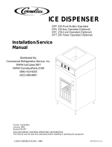
SINK DRAIN ASSEMBLY
1.Usetube,clamp and insulation provided to assemble drain.
2.To assure properdrainage,do notallow“trap”toformin drainline.Besure drainline runsflatwith bottom
ofdispenser (see Figure 1)
DISPENSER BOTTOM
DRAINLINE
FIGURE1.SINK DRAIN ASSEMBLY

4
90632
CLEANINGINSTRUCTIONS
WARNING:Disconnectpowerbefore cleaning.Do notuse metalscrapers,sharp objectsor
abrasives on the surface of theliner,as damagemay result.Do notuse solventsorother
cleaning agents,as they may attack theplasticliner.
DISPENSER
1.Clean the ice dispenserinterioratleastonceamonth.
2.Lift off agitatorassemblyand wash and rinseit thoroughly.
3.Carefullyremove and disassemblethe deflectorassemblyand wash and rinse all parts.
4.Wash downthe inside ofhopperand top coverwithmild detergentsolution and rinsethoroughlytoremove
all tracesofdetergent.
5.Replace agitatorand deflectorassembly,using caretoreinstall the bulbsproperly.
6.Sanitizethe inside ofhopperand agitatorwithasolution of1 ounce ofhousehold bleachin 1 gallon ofwa-
ter.
7.Withthe brush provided,clean the inside of the icechutewithamild detergentsolution and rinsethorough-
lytoremove all tracesofdetergent. Sanitize asdescribed instep 6.
COLDPLATEwhen required
1.Carefullyremovethe lowerfrontpanelof the ice dispenser.
2.Removecold platecoverbylifting slightlyinfrontand slide forward.
3.Wash downthe inside of the cold platecabinetand coverwithmild detergentsolution and rinse.Asmall,
long-handled brushwill be found helpful inreaching the corners.
4.Replacethe cover, taking carethatitis securelypositioned incold platetray.
5.Replace and lowerfrontpanel,carefullyfeeding the tubesand wiresintothe cabinet. Besure not to pinch
anytubing orwiresbetween the paneland cabinet.
BEVERAGE SYSTEM(when required)
1.Removefaucetspouts,washinmild detergent, rinse and replace.
2.Disconnectelectricalpowertothe carbonator.Shutoff the watersupplyand closethe CO2regulatortothe
carbonator.
3.Disconnect the syrup tanks fromthe system.
4.Energizethe beverage faucetsto purge the remaining soda waterinthe system.
5.Useaclean 5 gallon tankforeach of the following:
A.Cleaning Tank-- Fill with hot(120° -- 140°)potablewater.

590632
B.Sanitation Tank-- Fil withachlorine sanitizing solution inthe strength of1 ounce ofhousehold bleach
(sodiumhypochlorite)to 1 gallon ofcold(ambient)potablewater (410PPM).
6.Repeat the following procedure on each of the unit’s syrup productlines.
A.Connect the cleaning tanktothe syrup line tobesanitized and tothe CO2system.
B.Energizethe beverage faucetuntil the liquid dispensed isfree ofany syrup.
C.Disconnect the cleaning tankand hook-up the sanitizing tanktothe syrup line and CO2system.
D.Energizethe beverage faucetuntil the chlorine sanitizing solution isdispensed through the faucet.
Flush atleast2cupsofliquidtoinsurethat the sanitizing solution hasfilled the entirelength of the
syrup line.
E.Disconnect the sanitizing tank.Hookup the product tanktothe syrup line and tothe CO2system.
F.Energizethe faucet toflushthe sanitizing solution fromthe syrup line and faucet. Continue drawon
faucetuntil only syrup isdispensed.
7.RepeatStep2inreverse ordertoturnonthe carbonator.Dispense atlease1cup ofbeverage fromeach
faucet. Check taste,continue toflush,ifneeded, to obtainsatisfactorytasting drink.
OPERATING INSTRUCTIONS
1.iceDispensing.Depressing the operating levelactivatesamicroswitch behind the frontpanel,Which ener-
gizesthe agitatormotorand gatesolenoid.This causesthe agitatortorotate and the gateslide toleft, al-
lowing iceto push out the gate opening.
2.AutomaticIceFilling.Twothermostatic capillary controlsare utilized.The controlcapillaryof the ice dis-
penser (agitation bulb)will activatethe agitation timerasitsensesice.The agitation timercausesthe iceto
levelwhich allowsthe entireicestorage bintofill beforethe icemachine shutsoff. When the icelevelre-
mainsat the deflectorafteragitation, the icemakercontrolcapillary(icemakerbulb)stopsicemakeropera-
tion until the leveldrops,and the bulbswarmup
Whilethe icemakerisrunning, the ice entering the hopperfromthe feed tube shouldbeloose and insmall
pieces. Ice entering inthe formofhard packed cylindersindicatesarestriction ordistortion of the feed
tube,and couldresultinicemakermalfunction ofnotcorrected.
Immediatelyaftericemakershutoff, observethe iceinthe hopperbetween the feed tube entrance and the
deflector.Itshouldbelooselypressed against the top of the deflector,indicating correct thermostatopera-
tion. If the icelevel islow,orificeispacked hard against the deflectoritwill be necessarytoreadjust the
icemakerbincontrol,according tothe icemakerinstructions.(Adjust the controlwarmertolowerthe ice
level,and coldertoraisethe icelevel)
3.Beverage System.(--AB and --ABCmodelsonly)Beveragesmaybe dispensed byoperating the leveron
the appropriatefaucets.On unitswithcold plates(--ABC),periodicmovementof the iceinthe hopperis
necessarytomaintainthe leveloficeonthe cold plate.Oninitialstartup,ofafterlong idle period with no
use,dispensing icefor20--30 secondsisnecessarytofill the cold plate,orwarmbeveragesmaybe experi-
enced.

6
90632
SERVICEAND MAINTENANCE
CAUTION:Disconnectpowerto dispenserbeforeinstalling,removing oradjusting this kit.
INSTALL PLATEON
STUDSAS SHOWN
FIGURE2. GATERESTRICTORPLATE
ADJUSTMENTS
Thisdispenserisprovided with a gaterestrictorplate,installed inithighestposition.Thisplate adjuststhe rate
oficeflowfromthe dispenser. In applicationsusing buckets,carafesorotherlarge containers, the platemaybe
removed entirelyformaximumiceflow.Forglassesand cups, the platemaybe adjusted downwardtoreduce
the flowofice.The bestposition dependson the type ofice being used and the sizecontainerand mustbe
found bytrialand error.Adjustmentismade byloosening the uppertwoicechuteretaining nuts,sliding the re-
strictorplatetothe desired position and re-tightening the nuts.

790632
TROUBLESHOOTING GUIDE
Shouldyourunit fail to operate properly,check that thereispowertothe unitand that the hoppercontainsice. If
the unitstill doesnotdispense,check the following chartunderthe appropriatesymptomsto aidinlocating the
defect.
TroubleProbableCause
BLOWNFUSE OR CIRCUITBREAKER.A.Shortcircuitinwiring.
B.Defective gatesolenoid.
C.Defective agitatormotor.
GATEDOES NOTOPEN.AGITATOR DOES NOT
TURN.A.No power.
B.Bentdepressorplate(doesnotactuate
switch).
C.Defective dispensing switch.
GATEDOES NOTOPENORIS SLUGGISH.
AGITATORTURNS.A.Defective gatesolenoid.
B.Weakgatespring.
C.Excessive pressure againstgateslide.
GATEOPENS.AGITATOR DOES NOT TURN.A. Icesolidified in hopper.
B.Defective agitatormotor.
C.Defectivecapacitor (TJ90 only).
ICEDISPENSES CONTINUOUSLY.A.Stuck orbentdepressorplate(doesnot
releaseswitch)
B.Defective dispensing switch.
C. Improperswitchinstallation.
SLUSHYICE.WATERIN HOPPER.A.Blocked drain.
B.Unitno level.
ICE SOLIDIFIEDIN HOPPER,ORICE ATREAR
CORNERONLY.A.Defective orimproperlyadjusted thermostat.
B.Defective agitation timer.
NOICEIN HOPPERA. Icemakermalfunction.
ICE PACKEDIN HOPPER.A.Defective orimproperlyadjusted control(not
shutting off).
BEVERAGES DONOTDISPENSE.A.No24voltpowertofaucets.
B.NoCO2pressure.
BEVERAGES TOO SWEET.A.Carbonatornotworking.
B.NoCO2pressureincarbonator.
C.Faucetbrixrequiresadjusting.
BEVERAGES NOTSWEETENOUGH.A.Empty syrup tank.
B.Faucetbrixrequiresadjusting.
BEVERAGES NOTCOLD(UNITSWITHBUILT-IN
COLDPLATE).A.Unitstanding withnoice use-no iceincold
platecabinet.
NOTE:contactyourlocalsyrup orbeverage equipmentdistributorforadditional information and trou-
bleshooting ofbeverage system.

890632
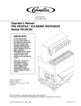
FIGURE 3. MOUNTING TEMPLATE
OUTLINE
OF UNIT
NOTE: 1)SHADED AREA INDICATE OPENINGS IN CABINET
BOTTOM NEEDED FOR UTILITIES AND BEVERAGE
TUBING.
2) * INDICATES 1/2” DIA. ACCESS HOLE FOR
ICEMAKER CONTROL BULB.
TJ90--AB, ABC
OUTLINE
OF UNIT
18- 7/8-IN.
2- 5/16-IN.
6- 17/ 32 IN.
2 -1/8-DIA.
4- 1/2-IN.
5/8-IN.
27- 23/32-IN.
22-IN.
4-IN.
3/4-IN.
21 -25/32-IN. 18-9/16-IN.
7-1/2-IN.
15 7/8-IN.
TJ45--AB
8 *
5/8 IN. 2 *
10- 5/8 IN
1- 1/8 IN
1- 1/4 IN
19-3/4 IN1-1/8 IN
16-1/4 IN
3/8 DIA
3 PLACES
1-1/8 IN 3/4 IN
9-3/4 IN 2 *
1-5/8 IN
12-5/8 IN 1-5/8 IN
3/8 DIA
3 PLACES

990632
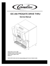
FIGURE 4. TYPICAL POST-MIX BEVERAGE SYSTEM
SCHEMATIC “--B” DISPENSERS
1
2
3
4
FAUCETS
6
7
8
CW
5
CW
5--15
PSIG
OPTIONAL FOR DIET OR ROOT BEER
S1 S2 S3 S4
COLD PLATE OR
REFRIGERATED
ICE BANK
S5 S6 S7 S8
15--50 PSIG
CARBONATOR
60-100 PSIG
FILTER
WATER
SUPPLY
OPTIONAL
PRESSURE REGULATOR
SYRUP
TANKS
CO2TANK
REGULATOR
NOTE:
FOR REFERENCE ONLY -- NOT
FOR CONTRUCTION.
REMCPR “--B” ICE/BEVERAGE DISPENSER
ITEMS OUTSIDE OF BROKEN LINES NOT
INCLUDED WITH UNIT.

10 90632
FIGURE 5. TYPICAL POST-MIX BEVERAGE SYSTEM
SCHEMATIC “--BC” DISPENSERS
1
2
3
4
FAUCETS
6
7
8
CW
5
CW
5--15
PSIG
OPTIONAL FOR DIET OR ROOT BEER
S1 S2 S3 S4
COLD PLATE OR
REFRIGERATED
ICE BANK
S5 S6 S7 S8
15--50 PSIG
CARBONATOR
60-100 PSIG
FILTER
WATER
SUPPLY
OPTIONAL
PRESSURE REGULATOR
SYRUP
TANKS
CO2TANK
REGULATOR
NOTE:
FOR REFERENCE ONLY -- NOT
FOR CONTRUCTION.
REMCPR “--B” ICE/BEVERAGE DISPENSER
ITEMS OUTSIDE OF BROKEN LINES NOT
INCLUDED WITH UNIT.
COLD PLATE

90632
11
ELECTRIC
CONDUITDISPENSER
DRAIN
ICEMAKER
SEE INSTALLATION KITINSTRUCTIONFORFEEDTUBEDETAILS
HOT
GRND.
BLK.WHT.NEUTRAL
FIELDSUPPLYCONDUIT
FIELDWIRING
COMPARTMENT
LOWER CABINET
ICEMAKER
ROUTEICEMAKER
BULB AS SHOWN
DISPENSER
FASTEN&SEAL
TOCOUNTER
FIGURE6. INSTALLATION
FIGURE7.FIELDWIRING

90632
1
2
END OFINSTALLED
BULBPROTRUDES
APPROX1/4”TYPICAL
ALUMINUM
PLATE
STAINLESS
DEFLECTOR
AGITATION
BULB--
BOTTOM
ICEMAKER
BULB-- TOP
FIGURE8.DEFLECTOR ASSEMBLY
DEFLECTOR ASSEMBLY
INSTALL BAREBULBS
AS SHOWN ABOVE
ICEMAKER BULB
WITHINSULATION
TUBINGUPTO
DEFLECTOR
AGITATION BULB
INSULATINGTUBING
UPTODEFLECTOR
FIGURE9.HOPPERINTERIOR

90632
13
DANGER:ELECTRICSHOCK HAZARD DISCONNECT
POWER BEFORE SERVICINGUNIT
*T’STATIS SHOWNIN
WARMPOSITION.
GRN.
GRD.WHT.
MOTOR HEATER
LNGATE
SOL.
1-1/4AMPTIME
DELAYFUSE.
“ON”“OFF”
WHT
AGITATIONTIMER
INPUT
NO
NC
C
B
L
U
LID SWITCH
(LID SCREWMUSTBE
IN PLACEFOR AGITA-
TOROPERATION)
B
L
U
E
BLK
R
E
D
RED
R
E
D
RD
AGITATOR
MOTOR
CAP.
(TJ90ONLY)
R
E
D
WHT
BLK
23
1
T’STAT*
WHT
CAP.
BLK
BLK
WHT
COLDPLATE
MOTOROPTION
KEY
SWITCH
OPTION
24V.TRANS.
BEVERAGE
FAUCET
TYPICAL
BEVERAGE SYSTEM
BLK
DISPENSE
SWITCH
TERMINAL
BOARD
TDSW
WHT
RED
BLK
OR
RED
PORTION
TIMER
DISPENSE
SWITCH
PORTION
CONTROL
OPTION
TO
TERMINAL
BOARD
7/8WHEN REPLACINGSOLENOID
ADJUST TO7/8AS SHOWN
BEFORETIGHTENINGMOUNTING
SCREWS
SOLENOID ADJUSTMENT
FIGURE10.WIRINGDIAGRAMTJ45,90-A DISPENSER
SERVICEINFORMATION

1490632
FIGURE11 UPPERSECTIONEXPLODEDVIEWTJ45
FIGURE12 EXPLODEDVIEWLOWERSECTIONTJ45
1
2
3
4
5
67
8
9
10
11
12
13
14
15
15
16
18
20
22
23
24
26 2728

15 90632
FIGURE13 EXPLODEDVIEWUPPERSECTIONTJ90
FIGURE14 EXPLODEDVIEWLOWERSECTIONTJ90
1
2
3
4
5
67
8
9
10
11
12
13
14
15
15
16
17
18
20
21
22
23
26
27
28

1690632
PARTSLIST
ItemNo.PartNo.TJ45
-A-AB PartNo.TJ90
-A,-AB,-ABC Description
1 21491 21491 GateSlide
2 30528 30528 Interlock Switch
3 21515 21515 DepressorLever
4 21948 21932 Agitator (-A,-AB ModelsOnly)
---------- 21958 Agitator (-ABCModelsOnly)
5 30895 30895 DispenseSwitch
6 31007 31007 SwitchBoot
7 31163 31163 SwitchInsert
8 31091 31091 Transformer
9 31106 31112 AgitatorMotor
10 50454 50454 MotorShaft Seal
11 50481 50806 MotorGasket
12 50800 50801 Lid
13 50750 50793 Sink(-A,-AB,ModelsOnly)
1
3
---------- 51019 (-ABCModelsOnly)
14 53015 53015 IceChuteBack Section
53016 53016 IceChuteCover
15 50770 50770 GateGasket
16 70426 70441 SinkGrill
17 ---------- 30774 Capacitor
18 31093 31093 SolenoidAssembly
19 70438 70438 Rebuilding Kit
20 22644 22644 DepressorRetainer
21 ---------- 30794 Agitation MotorHeater (ABCModelsOnly)
22 21575 21575 DeflectorAssy
23 21929 21929 IceCutter
24 21934 ---------- Ice LevelRod
25 ---------- 22081 GateRestrictor
26 23062 23062 FoamShield
27 31290 31290 Agitation Timer
28 31001 31001 Thermostat

17 90632
123
4
4
5
6
7
8
9
10
11
12
13
14
15
16
17
18
19
19
20
21
22
22
22
FIGURE15.SOLENOID ASSEMBLY
Index
No.PartNo. Qty.Name
1 21493 1 SolenoidMounting Plate
2# 31551 1 SolenoidServiceKit
3 70171 2 8--32 x3/8Phil TrHD Screw
4 70121 2 No.8 Lockwasher
5 50752 3 Isolator
6*50789 2 BumperAssembly
7*70423 1 CotterPin
8*10080 1 Gate Lift Rod
9 10081 1 Gate Lift Rod Bushing
10 50754 1 GateArmBearing
11 21492 1 Gatelift Arm
12 70043 1 Flatwasher
13*70422 1 Spring
14 70263 1 1/4-20 x3/4HexHdScrew
15 70048 1 1/4 Lockwasher
16 70066 1 1/4Flatwasher
17 10077 1 PivotBearing
18 30227 1 1/4Quick ConnectTab
19 50305 ---- Lubricant
20*21592 1 Solenoid Linkage Pin
21*70433 2 RetainerRing
22 51088 ---- Loctite
----*70438 ---- Rebuilding Kit
NOTE:*Parts suppliedwithrebuilding kit.
# 31551 solenoidsuppliedwithitems20&21.

18 Manualnumber
IMICORNELIUSINC.
ONECORNELIUSPLACE
ANOKA,MN.55303--6234
TELEPHONE(800)238--3600
FACSIMILE (612)422--3232
TECHSVC1-800-535-4240
WARRANTY
IMICorneliusInc.and RemcorProductsCompany warrantsthatall equipmentand partsarefree fromdefects
inmaterialand workmanship undernormaluse and service.Fora copy ofthewarrantyapplicableto your
Corneliusand orRemcorproduct,in yourcountry,pleasewrite,fax ortelephonetheIMICorneliusoffice near-
estyou.Pleaseprovidethe equipmentmodelnumber,serialnumberand thedateofpurchase.
IMICorneliusOffices
AUSTRALIADP.O.210,DRIVERWOOD,DNSW2210,AUSTRALIAD(61)2 533 3122 DFAX (61)2 534 2166
AUSTRIADAMLANGENFELDE32 DA-1222 DVIENNA,AUSTRIAD(43)1 233 520 DFAX (43)1-2335-2930
BELGIUMDBOSKAPELLEI122 DB-2930 BRAASCHAAT,BELGIUMD(32)3 664 0552 DFAX (32)3 665 2307
BRAZILDRUA ITAOCARA97 DTOMASCOELHO DRIO DEJANEIRO,BRAZILD(55)21 591 7150 DFAX (55)21 593 1829
ENGLAND DTYTHING ROAD ALCESTERDWARWICKSHIRE,B496EU,ENGLAND D(44)789 763 101 DFAX (44)789 763 644
FRANCED71 ROUTE DEST.DENISDF-95170 DEUIL LABARREDPARIS,FRANCED(33)1 34 28 6200 DFAX (33)1 34 28 6201
GERMANY DCARL LEVERKUS STRASSE15 DD-4018 LANGENFELD,GERMANY D(49)2173 7930 DFAX (49)2173 77 438
GREECED488 MESSOGION AVENUEDAGIAPARASKEVID153 42 DATHENS,GREECED(30)1 600 1073 DFAX (30)1 601 2491
HONG KONG D1104 TAIKOTSUICENTRED11-15 KOK CHEUNG STDTAIKOKTSUE,HONG KONG D(852)789 9882 DFAX (852)391 6222
ITALYDVIAPELLIZZARI11 D1-20059 DVIMARCATE,ITALYD(39)39 608 0817 DFAX (39)39 608 0814
NEWZEALAND D20 LANSFORDCRES.DP.O.BOX 19-044 AVONDALE DAUCKLAND 7,NEWZEALAND D(64)9 8200 357 DFAX (64)9 8200 361
SINGAPORED16 TUAS STREET DSINGAPORE2263 D(65)862 5542 DFAX (65)862 5604
SPAINDPOLIGONO INDUSTRAILDRIERA DEL FONOLLARDE-08830 SANTBOIDE LLOBREGATDBARCELONA,SPAIND(34)3 640 2839 DFAX (34)3 654 3379
USADONECORNELIUS PLACEDANOKA,MINNESOTAD(612)421-6120 DFAX (612)422-3255
/