Page is loading ...

INSTALLATION INSTRUCTIONS
AND USER GUIDE
VB0188
PRO301
HEAT RECOVERY VENTILATOR
Venmar Ventilation inc., 550 lemire BlVd., drummondVille, Qc. canada J2c 7W9
WWW.Venmar.ca
* This product earned the ENERGY STAR
®
by meeting strict energy efficiency guidelines set by Natural Resources
Canada and the US EPA. It meets ENERGY STAR requirements only when used in Canada.
Residential indooR use only
V
Q
0009
!
V
Q
0009
!
READ AND SAVE THESE INSTRUCTIONS
20847 rev. 02

First, we want to congratulate you on your purchase of this excellent unit which will allow you and your family to enjoy clean and healthy
air throughout your home for years to come!
Please take note that this manual uses the following symbols to emphasize particular information:
Identifies an instruction which, if not followed, might cause serious personal injuries including possibility of death.
Identifies an instruction which, if not followed, may severely damage the unit and/or its components.
NOTE: Indicates supplementary information needed to fully complete an instruction.
2
WARNING
!
CAUTION
ABOUT THIS GUIDE
ABOUT THESE UNITS
LIMITATION
For residential (domestic) installation only. Installation work and electrical wiring must be done by a qualified person(s) in accordance with
all applicable codes and standards, including fire-rated construction codes and standards.
WARNING
V
Q
0009
!
TO REDUCE THE RISK OF FIRE, ELECTRIC SHOCK, OR INJURY TO PERSON(S) OBSERVE THE FOLLOWING:
1. Use this unit only in the manner intended by the manufacturer. If you have questions, contact the manufacturer at the address or
telephone number listed in the warranty.
2. We recommend that your unit be inspected by a specialized technician once a year.
3. Before servicing or cleaning the unit, disconnect power cord from electrical outlet.
4. This unit is not designed to provide combustion and/or dilution air for fuel-burning appliances.
5. When cutting or drilling into wall or ceiling, do not damage electrical wiring and other hidden utilities.
6. Do not use the unit with any solid-state speed control device other than the ones listed below:
7. This unit must be grounded. The power supply cord has a 3-prong grounding plug for your personal safety. It must be plugged into a
mating 3-prong grounding receptacle, grounded in accordance with the national electrical code and local codes and ordinances.
Do not remove the ground prong. Do not use an extension cord.
8. Do not install in a cooking area or connect directly to any appliances.
9. Do not use to exhaust hazardous or explosive materials and vapors.
10. When performing installation, servicing or cleaning the unit, it is recommended to wear safety glasses and gloves.
11. Due to the weight of the unit, two installers are recommended to perform installation.
12. When applicable local regulations comprise more restrictive installation and/or certification requirements, the aforementioned requirements
prevail on those of this document and the installer agrees to conform to these at his own expenses.
Main ContRol auxiliaRy ContRol
lite-touch Pro 20-minute lighted Push Button
CAUTION
1. To avoid prematurate clogged filters, turn OFF the unit during construction or renovation.
2. Please read specification label on product for further information and requirements.
3. Be sure to duct air outside – Do not intake/exhaust air into spaces within walls or ceiling or into attics, crawl spaces, or garage.
4. Intended for residential installation only in accordance with the requirements of Part 9 of the National Building Code of Canada.
5. Do not run any air ducts directly above or closer than 2 ft (0.61 m) to any furnace or its supply plenum, boiler, or other heat producing
appliance. If a duct has to be connected to the furnace return plenum, it must be connected not closer than 9’ 10” (3 m) from this plenum
connection to the furnace.
6. The ductwork is intended to be installed in compliance with all applicable codes.
7. When leaving the house for a long period of time (more than two weeks), a responsible person should regularly check if the unit
operates adequately.
8. If the ductwork passes through an unconditioned space (e.g.: attic), the unit must operate continuously except when performing
maintenance and/or repair. Also, the ambient temperature of the house should never drop below 18°C (65°F).

table of Contents
3
1. tyPical installations. . . . . . . . . . . . . . . . . . . . . . . . . . . . . . . . . . . . . . . . . . . . . . 4
1.1 Fully ducted system . . . . . . . . . . . . . . . . . . . . . . . . . . . . . . . . . . . . . . . . . . . . . . . . 4
1.2 central draW Point . . . . . . . . . . . . . . . . . . . . . . . . . . . . . . . . . . . . . . . . . . . . . . . . 4
1.3 simPliFied installation . . . . . . . . . . . . . . . . . . . . . . . . . . . . . . . . . . . . . . . . . . . . . . . 4
2. dimensions . . . . . . . . . . . . . . . . . . . . . . . . . . . . . . . . . . . . . . . . . . . . . . . . . . 5
3. installation . . . . . . . . . . . . . . . . . . . . . . . . . . . . . . . . . . . . . . . . . . . . . . . . 5-10
3.1 insPect the content oF the Box . . . . . . . . . . . . . . . . . . . . . . . . . . . . . . . . . . . . . . . . . . 5
3.2 installation Kit, tools and material . . . . . . . . . . . . . . . . . . . . . . . . . . . . . . . . . . . . . . . . 6
3.3 locating the unit . . . . . . . . . . . . . . . . . . . . . . . . . . . . . . . . . . . . . . . . . . . . . . . . . 6
3.4 Planning oF the ductWorK . . . . . . . . . . . . . . . . . . . . . . . . . . . . . . . . . . . . . . . . . . . . . 6
3.5 installing non-insulated ducts and diFFusers . . . . . . . . . . . . . . . . . . . . . . . . . . . . . . . . . . 6-8
3.5.1 Fully ducted system . . . . . . . . . . . . . . . . . . . . . . . . . . . . . . . . . . . . . . . . . . . . . . . . . 6-7
3.5.2 central draW Point . . . . . . . . . . . . . . . . . . . . . . . . . . . . . . . . . . . . . . . . . . . . . . . . . . 7
3.5.3 simPliFied installation. . . . . . . . . . . . . . . . . . . . . . . . . . . . . . . . . . . . . . . . . . . . . . . . . . 8
3.6 installing insulated FlexiBle ducts . . . . . . . . . . . . . . . . . . . . . . . . . . . . . . . . . . . . . . . 8-9
3.6.1 connection to the unit Ports . . . . . . . . . . . . . . . . . . . . . . . . . . . . . . . . . . . . . . . . . . . . . 8
3.6.2 locating exterior Ports . . . . . . . . . . . . . . . . . . . . . . . . . . . . . . . . . . . . . . . . . . . . . . . . 9
3.7 connecting insulated ducts to exterior Ports . . . . . . . . . . . . . . . . . . . . . . . . . . . . . . . . . . 9
3.8 installing tandem
®
transition Kit . . . . . . . . . . . . . . . . . . . . . . . . . . . . . . . . . . . . . . . . 10
3.9 connecting the drain . . . . . . . . . . . . . . . . . . . . . . . . . . . . . . . . . . . . . . . . . . . . . . 10
4. controls . . . . . . . . . . . . . . . . . . . . . . . . . . . . . . . . . . . . . . . . . . . . . . . . . 11-13
4.1 Booting seQuence . . . . . . . . . . . . . . . . . . . . . . . . . . . . . . . . . . . . . . . . . . . . . . . . 11
4.2 deFrost cycles . . . . . . . . . . . . . . . . . . . . . . . . . . . . . . . . . . . . . . . . . . . . . . . . . 11
4.3 lite-touch Pro main Wall control installation . . . . . . . . . . . . . . . . . . . . . . . . . . . . . . . . 12
4.4 Wall control(s) connection to the unit . . . . . . . . . . . . . . . . . . . . . . . . . . . . . . . . . . . . 13
4.5 lite-touch Pro use . . . . . . . . . . . . . . . . . . . . . . . . . . . . . . . . . . . . . . . . . . . . . . 13
5. electric connection to the Furnace . . . . . . . . . . . . . . . . . . . . . . . . . . . . . . . . . . . . 14
6. Wiring diagram . . . . . . . . . . . . . . . . . . . . . . . . . . . . . . . . . . . . . . . . . . . . . . . 15
7. maintenance. . . . . . . . . . . . . . . . . . . . . . . . . . . . . . . . . . . . . . . . . . . . . . . . 16-17
7.1 eVery three months . . . . . . . . . . . . . . . . . . . . . . . . . . . . . . . . . . . . . . . . . . . . . . . 16
7.2 annual maintenance . . . . . . . . . . . . . . . . . . . . . . . . . . . . . . . . . . . . . . . . . . . . . . . 17
8. serVice Parts . . . . . . . . . . . . . . . . . . . . . . . . . . . . . . . . . . . . . . . . . . . . . . . . 17
9. trouBleshooting . . . . . . . . . . . . . . . . . . . . . . . . . . . . . . . . . . . . . . . . . . . . . . 18
10. Warranty . . . . . . . . . . . . . . . . . . . . . . . . . . . . . . . . . . . . . . . . . . . . . . . . . . 19

4
1. typiCal installations
Use the following illustrations as guidelines to help you decide on how the unit will be installed.
All the units should be hung from the joists.
In every case, bathroom fans and a range hood could be used to exhaust stale air. However, please note that an optional bathroom ins-
tallation kit (part no. IKBV1000 or IKBB1000) is available for house where there is no bathroom fans. Also, for homes with more than one
level, we recommend one exhaust register at the highest level.
There are 3 installation methods: Fully Ducted System, Central Draw Point and Simplified Installation.
NOTE: An electrical outlet has to be available within 3 feet of the unit.
1.1 Fully ducted system (Primarily For homes With radiant hot Water or electric BaseBoard heating)
VH0091
Stale air coming from the register located at the highest level of the
house is exhausted to the outside. Fresh air from outside is filtered and
supplied by the register located in the lowest liveable level.
Homes with more than one level require at least one exhaust register at
the highest level.
See figure at right.
1.2 central draW Point (connection to a Forced air system)
VH0092
Stale air coming from the register located at the highest level of the
house is exhausted to the outside. Fresh air from outside is filtered and
supplied to the return (plenum) or the supply duct of the forced air unit.
See figure at right.
For this type of installation, it is not essential that the forced air system
blower runs when the unit is in operation, but we recommend it.
NOTE: Home with multiple forced air systems should have one unit on
each system.
1.3 simPliFied installation (connection to a Forced air system)
VH0093
Stale air is exhausted to the outside. Fresh air from outside is filtered and
supplied to the return (plenum) or the supply duct of the forced air unit.
See figure at right.
To avoid cross-contamination and achieve the highest efficiencies, the
forced air system blower must always be ON.
NOTE: Home with multiple forced air systems should have one unit on
each system.
Do not connect the unit to any forced air system supply
duct.
CAUTION
Do not connect the unit to any forced air system supply
duct.
CAUTION

5
2. diMensions
11¼”
17
7
/16”
37
7
/16”
35
7
/8”
31”
11
7
/8”
VK0081A
3. installation
3.1 insPect the content oF the Box
• Inspect the inside of the unit for damage. Ensure that blower assembly, heat recovery core, core filters, insulation, dampers,
etc. are all intact, then reinstall the unit door.
• Inspect the exterior of the unit for shipping damage. Ensure that there is no damage to the door, ports, power cord, etc.
In order to prevent damages to the door hooks, do not
open completely the unit door; tilt it about 3” from
the unit base and lift it up. See illustration below.
CAUTION
±3”
VD0303A
B
C
VD0302
A
• Using a Phillips or a Robertson screwdriver, loosen both
door screws (A).
NOTE: The screws will stay attached to the door.
• Open (B) and lift out (C) the door.
NOTE: Before proceeding to the installation, check the content of the box. If items are missing or damaged, contact the
manufacturer. Remove all packaging material from the unit.

6
3. installation (Cont’d)
3.3 locating the unit
Choose an appropriate location for the unit.
• Within an area of the house where the ambient temperature is kept between 10°C (50°F) and 40°C (104°F).
• Away from living areas (dining room, living room, bedroom), if possible.
• So as to provide easy access to the interior of the unit, for maintenance.
• Close to an exterior wall, so as to limit the length of the insulated flexible duct to and from the unit.
• Away from hot chimneys and other fire hazards.
• Allow for a power source (standard 3-prong grounding outlet).
• Close to a drain. If no drain is close by, use a pail to collect run-off.
Hang the unit with the four hooks, chains and springs provided. See illustration at right.
VD0305
Make sure the unit is level.
CAUTION
Stale air exhaust ductwork
• Install the stale air exhaust diffuser in the main area where the contaminants are produced: kitchen, living room, etc. Position
the diffuser as far from the stairway as possible and in such a way that the air circulates in all the lived-in spaces in the house.
If desired, you can install another diffuser (sold separately).
• If a diffuser is installed in the kitchen, it must be located at least 4 feet (1.2 m) from the range.
• Install the diffuser 6 to 12 inches (152 to 305 mm) from the ceiling on an interior wall OR install it in the ceiling.
Never install a stale air exhaust diffuser in a closed room where a combustion device operates, such as a
gas furnace, a gas water heater or a fireplace.
WARNING
!
3.2 installation Kit, tools and material
The installation kit needed to perform most installations is no. IKSP1000. Following are the tools and material needed:
• Phillips no. 2 or Robertson no. 2 screwdriver
• Small flat blade screwdriver (for wall control connection)
• Wire stripper (for wall control connection)
• Hammer and flat blade screwdriver (for plenum connection installation only, to make holes in existing metal duct)
• Scissors or utility knife (to cut duct tape)
• Measuring tape
• Duct tape
• Tin snips or metal shear (for plenum connection installation only, to cut ductwork)
• Aluminum duct tape (for plenum connection installation only)
• Jig saw
• Caulking gun and caulking.
3.4 Planning oF the ductWorK
• Keep it simple. Plan for a minimum of bends and joints.
• Keep the length of insulated ducts to a minimum.
• Do not ventilate crawl spaces or cold rooms. Do not attempt to recover the exhaust air from a dryer or a range hood. This
would cause clogging of the filters and recovery module.
• If the house has two floors or more, be sure to plan for at least one exhaust register on the highest lived-in level.
3.5 installing non-insulated ducts and diFFusers
3.5.1 Fully ducted system (as illustrated in section 1.1)

7
3.5 installing non-insulated ducts and diFFusers (cont’d)
3.5.1 Fully ducted system (as illustrated in section 1.1) (cont’d)
How to ConneCt tHe flexible duCts to tHe diffuseRs
Once the diffusers location is determined, cut out 5¼” diameter hole.
Run one end of the flexible duct through the hole and fix it to the diffuser base (1),
using a tie wrap and duct tape. Assemble the diffuser base to the wall (or ceiling)
using its 4 no. 8 x 3/4” screws. Then, slide in the diffuser (2).
See illustration at right.
Ø 5¼”
VJ0094A
2
1
3. installation (Cont’d)
How to ConneCt tHe flexible duCts to tHe unit poRts
Both flexible ducts attached to the diffusers must be connected to the bottom ports of
the unit. When facing the unit door, the fresh air to building port is located on left side
and the exhaust air from building port is on the right side. Refer to the identification
labels affixed beside each unit ports. Using tie wrap, attach the fresh air to building
duct to its corresponding port, then do the same for the exhaust air to building duct
and port. See illustration at right.
NOTE: Use an insulated duct (not included) if the duct will have to go through a
space where it is possible to experience extreme temperature conditions
(eg: in northern area, unheated attic in winter or uncooled attic in southern
area). Also, if you plan to stop the unit for more than 12 hours, we recommend
to cover the duct with R12 insulation.
VJ0097
RigHt side of tHe unit
Stale air exhaust ductwork
Same as for Fully Ducted System, described in step 3.5.1
3.5.2 central draW Point (as illustrated in section 1.2)
Fresh air distribution ductwork
When performing duct connections, always use approved tools and materials. Respect all corresponding
laws and safety regulations. Please refer to your local building code.
WARNING
!
• Locate the opening for fresh air ductwork on the forced air unit return duct
at a minimum linear distance of 9’ 10” (3 m) upstream (from forced air unit drop:
A+B+C). Cut out a 5” Ø hole in this location, using metal shear.
• Use a metal transition (not included, available in hardware store) to connect the
unit duct to the forced air unit return duct.
• Attach the other end of the flexible duct to the Fresh air to building port (see
icon on the left side of the unit). Use tie wrap and duct tape to seal the connection.
See illustration at right.
Fresh air distribution ductwork
• Install the fresh air distribution diffuser in a large, open area in the lowest level to ensure the greatest possible air circulation.
• Keep in mind that the fresh air diffuser must be located as far as possible from the stale air diffuser. If desired, you can install
another diffuser (sold separately).
• Install the diffuser either in the ceiling OR 6 to 12 inches (152 to 305 mm) from the ceiling on an interior wall. (The cooler air
will then cross the upper part of the room and mix with room air, before descending to occupant’s level.)
• If a register must be floor installed, direct the airflow up the wall.
unit poRts identifiCation
Each unit port has an identification label
beside it to avoid wrong duct connections to
the unit. Always refer to these labels before
performing any duct and port connection.
VJ0095
unit
dooR
VJ0099
a + b + C = not less
tHan 9’ 10” (3 M)
unit dooR
Metal
tRansition

8
3.5 installing non-insulated ducts and diFFusers (cont’d)
Fresh air distribution ductwork (return side connection)
Same as for Central Draw Point, described in step 3.5.2
3.5.3 simPliFied installation (as illustrated in section 1.3)
Stale air exhaust ductwork (return side connection)
When performing duct connections, always use approved tools and materials. Respect all corresponding
laws and safety regulations. Please refer to your local building code.
WARNING
!
• Locate the opening for stale air ductwork on the forced air unit at least 3’ (0.9 m)
from fresh air ductwork connection. Cut out a 5” Ø hole in this location, using
metal shear.
• Use a steel transition (not included, available in hardware store) to connect the
unit duct to the forced air unit return duct.
• Attach the other end of the flexible duct to the Exhaust air from building port
(see icon on the right side of the unit). Use tie wrap and duct tape to seal the
connection. See illustration at right.
Make sure the furnace blower operation is synchronized with the unit operation! See Section 5.
CAUTION
3. installation (Cont’d)
3.6 installing insulated FlexiBle ducts
Make sure the vapor barrier on the insulated ducts does not tear during installation to avoid condensation
within the ducts.
CAUTION
3’ (0.9 M)
MiniMuM
unit dooR
a + b + C = not less
tHan 9’ 10” (3 M)
Use the following procedure for connecting the insulated flexible ducts to the unit ports (Exhaust air to outside and Fresh air from
outside). Refer to identification labels before performing any duct and port connection.
For both remaining ducts, pull back the insulation to expose
the interior flexible duct.
Connect the interior flexible duct to the smaller part of the
inner ring of the port using a tie wrap.
Pull the insulation over the joint and tuck it between the
inner and outer rings of the port. Pull the vapor barrier over
the insulation and over the outer ring of the port.
Apply duct tape gently to the joint in order to make an
airtight seal. See figures at right.
3.6.1 connection to the unit Ports
VJ0102
Avoid compressing the insulation when you pull the tape tightly around the joint. Compressed insulation
loses its insulation properties and causes water dripping due to condensation on the exterior surface of
the duct.
CAUTION

9
3. installation (Cont’d)
3.6 installing insulated FlexiBle ducts (cont’d)
Choose an appropriate location for installing the exterior ports:
• There must be a minimum distance of 6’ (1.8 m) between the hoods to avoid cross-contamination
• There must be a minimum distance of 18” (457 mm) from the ground
3.6.2 locating exterior Ports
VD0203
3.7 connecting insulated ducts to exterior Ports
Make sure the fresh air intake port is located at least 6 feet (1.8 m) away (or more, as per applicable building
codes or standards) from sources of contamination such as:
• Dryer exhaust, high efficiency furnace vent, central vacuum vent
• Gas meter exhaust, gas barbecue grill
• Garbage bin
• Any exhaust from a combustion source
WARNING
!
6’
(1.8 m)
6’
(1.8 m)
stale air
exhaust Port
18’’
(457 mm)
18’’ (457 mm)
5’’ Ø
(127 mm)
5’’ Ø
(127 mm)
Fresh air
intaKe Port
oPtional
location
• For each exterior port, using a jig saw, cut a 5’’ diameter hole in the
exterior wall.
• From the outside, slide the exterior port in place and attach it to the
exterior wall, using 2 no. 8 x 1½” provided screws. Seal the outline with
silicone.
• From the inside, pull back the insulation to expose the flexible duct and,
using a tie wrap, attach it to the exterior port rigid duct. Carefully seal
with duct tape. Pull the insulation over the joint. Pull the vapor barrier
over the insulation and over the joint. Apply gently duct tape to the joint
making an airtight seal. See illustration at right.
VR0028

10
3. installation (Cont’d)
3.9 connecting the drain
Cut two sections of plastic tubing, approximately
12” long, and connect each one to both inner drain
fittings located under the unit as shown.
Join these both sections to the “T” junction and
main tube as shown, to prevent the unit from
drawing unpleasant odors from the drain source.
VD0308A
± 1”
Run the tube to the floor
drain or to an alternative
drain pipe or pail.
IMPORTANT
If using a pail to collect
water, locate the tube end
approximately 1” from the
top of the pail in order to
prevent water from being
drawn back up into the unit.
VD0311A
± 12” ± 12”
TIE WRAP
3.8 installing tandem® transition* Kit
If desired, it is possible to perform insulated ducts connection with the outside
using the Tandem transition kit (purchase separately, part number 14690). The
joist opening needed to install the Tandem transition must be 9¾” minimum.
The maximum height of the Tandem transition is 8¾”. To connect the insulated
flexible ducts to the Tandem transition (Exhaust air to outside and Fresh air
from outside), follow the instructions included with the kit.
*Patented.
VR0003
Tandem transition kit

11
4. ContRols
This unit is equipped with an integrated defrost control located under the electrical compartment of the unit. Plug the unit.
4.1 Booting seQuence
The unit booting sequence is similar to a personnal computer boot sequence. Each time the unit is plugged after being unplugged, or
after a power failure, the unit will perform a booting sequence before starting to operate.
During the booting sequence, the integrated defrost control LED (2 in illustration below) will be OFF for 3 seconds, and then will turn
RED for the rest of the booting sequence (approximately 15 seconds). During this RED light phase, the unit is checking and resetting
the motorized damper position. Once the motorized damper position completely set, the booting sequence is done; the color of the
LED will show on which defrost cycle the unit is set.
NOTE: No command will be taken until the unit is fully booted.
4.2 deFrost cycles
Five seconds after the booting sequence is done, the LED (2) will light and stay lit to show in which
defrost cycle the unit is set. Use the push button (1) to change the defrost cycle of the unit (see table
below).
led ColoR defRost CyCle
green standard
red Plus
amBer discretion
If a problem occurs during the unit operation, its integrated control LED (2) will blink. The color of the blinking light depends on the
type of error detected. Refer to Section 9 Troubleshooting on last page for further details.
1
2
VD0310
According to your need, there are 3 defrost cycles available:
STANDARD: This is the factory set defrost cycle, which is the most commonly used to suit normal weather conditions. When
needed, the unit will perform defrost cycle on high speed.
PLUS: This mode has been created for people who live in cold region (outside temperature -27°C [-17°F] and lower). This
setting makes the unit perform defrost cycle on high speed for a longer period of time.
DISCRETION: When needed, the defrost cycle will be performed on the same speed than the unit ventilation speed. For example,
if the unit is set on high speed, the defrost cycle will be done on high speed, but if the unit is set on low speed, the
defrost cycle will be done on low speed.
NOTE: There is a 15-minute delay for the new defrost cycle choice to be kept in memory; if a power
failure occurs during this time delay, when the power returns, the unit resume to its previous
setting.

12
4. ContRols (Cont’d)
Always disconnect the unit before making any connections. Failure in disconnecting power could result in
electric shock or damage of the wall control or electronic module inside the unit.
WARNING
!
Failure to comply with the following can cause erratic operation of the unit and/or the wall control:
• Never install more than one main wall control per ventilation unit;
• Keep control low voltage wiring at least 1 foot (305 mm) away from motors, lighting ballast, light dimming
circuit and power distribution panel. Do not route control wiring alongside house power wiring;
• Ensure the wires are securely connected.
CAUTION
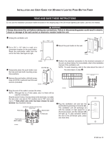
4.3 lite-touch Pro main Wall control installation
Cut a 2³/8” x 1³/8” hole in a wall, at a convenient location for the wall control. Route the control cable
(included) from the unit to this hole. See figure at right.
Temporarily place the switch over the hole and mark both mounting screw hole positions.
Remove the switch, drill both screw holes (3/16” Ø) in wall and insert the wall anchors.
NOTE: If the 20-minute lighted push-button is used, if activated, this optional auxiliary control will override the main control operation.
Strip the end of the cable to access the wires.
NOTE: Although this is a 4-wire cable, only 3 of them will be used for connection;
do not use the RED one.
Strip the end of BLACK, GREEN and YELLOW wires. Connect each wire to
its corresponding terminal: YELLOW wire to “OC’’, GREEN wire to “G’’ and
BLACK wire to “B’’. See illustration at right.
BG
OC
MAIN WALL CONTROL
LITE-TOUCH PRO
REAR VIEW
VE0274A
YELLOW wire
RED wire
(NOT USED)
BLACK wire
GREEN wire
VC
0132A
Ø 3/16”, typ.
Unplug the unit.
VC0133
Mount the wall control to the wall.

4. ContRols (Cont’d)
13
4.4 Wall control(s) connection to the unit
VE0275
Once the control(s) connection have been made, insert the terminal connector in the electrical
compartment interface. Plug the unit.
4.5 lite-touch Pro use
INTERMITTENT
MAX
MIN
VC0124
L-T
When power is applied for the first time or after a power failure, this control is in OFF mode.
Activate the wall control by pressing on MODE; the light indicator will show clearly in which operating mode the unit is.
Light Indicator Color Mode Suggested Use
GREEN INTERMITTENT
Select this mode when you are away from the house for
a few days. Also, when you deem the inside air is too dry
in heating season, or too humid during cooling season.
In this mode, the unit is OFF for 40 minutes per hour and
ventilates at minimum speed the remaining 20 minutes
of the hour.
YELLOW MIN Minimum ventilation speed for normal daily operation.
RED MAX
Maximum ventilation speed for excess pollutants and
humidity (parties, odors, smoke, etc.)
No light OFF Turn off the unit before performing maintenance.
Use the terminal connector included in the installation kit to perform the electrical connection
for main and optional wall controls. Check if all wires are correctly inserted in their
corresponding holes in the terminal block. (A wire is correctly inserted when its orange
receptacle is lower than another one without wire. On picture at right, wire A is correctly
inserted, but not wire B.)
Splice back the end of the cable to access the wires.
NOTE: Although this is a 4-wire cable, only 3 of them will be used for connection; do not
use the RED one.
Strip the end of BLACK, GREEN and YELLOW wires. Connect each wire to its corresponding
terminal: YELLOW wire to “Y’’, GREEN wire to “G’’ and BLACK wire to “B’’. Check if all wires
are correctly inserted in their corresponding holes in the terminal block.
Connect the auxiliary control cable, if installed (not shown).
VE0272
A
B

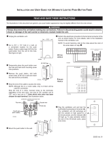
5. eleCtRiC ConneCtion to tHe fuRnaCe
Never connect a 120-volt AC circuit to the terminals of the furnace interlock (standard wiring). Only use the low
voltage class 2 circuit of the furnace blower control.
WARNING
!
On some electronic thermostats, energizing the “R” and “G” terminals at the furnace has the effect of energizing “Y” at the thermostat and
thereby turning on the cooling system (if present). If you identify this type of thermostat, you must use the alternate Furnace interlocK
Wiring.
W R G
Y
W
R
G
C
Y
UNIT TERMINAL CONNECTOR
THERMOSTAT
TERMINALS
FOUR
WIRES
TWO WIRES
heating only
FURNACE
24-VOLT
TERMINAL BLOCK
TWO WIRES
COOLING SYSTEM
NO C NC I OC OL Y R G B
W R G Y
W
R
Y
R
G
Y
C
THERMOSTAT
TERMINAL
4 WIRES
2 WIRES
heating only
wiring
nuts
FURNACE
24-VOLT
TERMINAL BLOCK
2 WIRES
COOLING SYSTEM
NO
NC
C
UNIT TERMINAL CONNECTOR
NO C NC I OC OL Y R G B
VE0108A
standaRd fuRnaCe inteRloCk wiRing (MeCHaniCal tHeRMostat)
alteRnate fuRnaCe inteRloCk wiRing
(ReCoMMended foR fuRnaCe witH eleCtRoniC tHeRMostat)
14

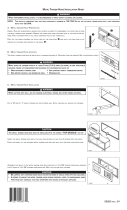
6. wiRing diagRaM
15
• Risk of electric shocks. Before performing any maintenance or servicing, always disconnect the unit from its power source.
• This product is equipped with an overload protection (fuse). A blown fuse indicates an overload or a short-circuit
situation. If the fuse blows, unplug the product and check the polarity and voltage output from the outlet. Replace
the fuse as per the servicing instructions (refer to wiring diagram for proper fuse rating) and verify the product. If
the replaced fuse blows, it may be a short-circuit and the product must be discarded or returned to an authorized
service center for examination and/or repair.
WARNING
!
WIRING DIAGRAM
Critical characteristic.
NOTES
1.Use specified UL listed/CSA Certified line fuse.
2. If any of the original wire, as supplied, must
be replaced, use the same equivalent wire.
3. Field wiring must comply with applicable
codes, ordinances and regulations.
4. Remote control (class 2 circuit) available,
see instruction manual.
5. Furnace fan circuit must be class 2 circuit only.
COLOR CODE
BK BLACK
BL BLUE
BN BROWN
GGREEN
RRED
WWHITE
Y YELLOW
nc no connection
OORANGE
PPURPLE
Line voltage factory wiring
Class 2 low voltage factory wiring
Class 2 low voltage field wiring
J11
12
T1
24 V
Class 2
9.5 V
Class 2
O
O
Y
Y
120 V
106 V
81 V
71 V
Neutral
W
BK
BL
P
BN
nc
nc
R
BN
P
BL
JU1
MH
123
J8
12345
J14
10
9
8
7
6
5
4
3
2
1
J13
ICP
1 2 3 4 5
J12
J9
1234
3A
3 AG Type
21
J10
ELECTRONIC ASSEMBLY
A1
F1
Override switch
(optional; see
notes 3 & 4)
Furnace blower
interlock (optional;
see notes 3, 5)
R1
Thermistor
J2
J1
1234512
J3
12
A2
D
AMPER
E
LECTRONIC
A
SSEMBLY
M2
Damper
Motor
BK
BK
BK
W
G
120 Volts AC
60 Hz
J6
J4
2
1
1
2
3
BK
BL
BR
Fan motor
M1
C1
Motor
capacitor
R
R
BK
G
Y
BK
G
R
Y
OL
OC
I
Field wiring
remote control
(see notes 3 & 4)
See note 1
120 V AC
Line
Neutral
J10-2 J10-1
F1 K2
K3
Fan motor M1
M
M
Damper motor M2
J4-1 J4-2
C1
Motor capacitor
J4-3J6-1 J6-2
J9-4
A2
J2-1 J3-1
J2-2 J3-2
J12-1
J12-2
K4
J8-2
J8-1
J8-5
J8-4
9.5 V AC
24 V AC
T1
nc nc
106 VAC
81 VAC
71 VAC
J9-3
J9-1
~
~
+-
CPU
K4K3K2
LOGIC DIAGRAM
VE0270A

16
7. MaintenanCe
Risk of electric shock. Before performing any maintenance, always turn off and disconnect the unit from its power
source.
WARNING
!
7.1 eVery three months
VD0005
Turn the unit OFF and
unplug it.
Using a Phillips or a Robertson screwdriver, loosen both
door screws (A).
NOTE: The screws will stay attached to the door.
Open (B) and lift out the door (C).
Slide out the heat recovery core (D), the core filters (E) and
the bottom filter retaining wire (F). See below.
Clean the inside wall of the unit with a damp cloth, then,
wipe with a dry one.
Remove dust on core using a vacuum cleaner with a soft
brush attachment. Wash both core filters under lukewarm
water with mild soap. Rinse thoroughly and let dry completely.
Reinstall the heat recovery core with its filters, as well as the
bottom filter retaining wire.
Reinstall the door, plug back the unit and turn it on.
NOTE: Allow a 20-second delay for boot sequence.
Regular maintenance should be performed every 3 months. Annual maintenance should take place every fall season.
VD0302
A
±3”
VD0303A
B
C
In order to prevent damages to the door hooks, do not
open completely the unit door; tilt it about 3” from
the unit base and lift it up. See illustration below.
CAUTION
VL0059
D
E
F

7. MaintenanCe (Cont’d)
17
7.2 annual maintenance
Repeat steps to and continue with the following steps:
Allow the heat recovery core to soak for 3 hours in a solution of warm water and mild soap (dishwashing liquid).
Rinse carefully, drain off water, and reinstall with its filters as well as the bottom filter retaining wire.
Check the exterior hood; make sure there are no leaves, twigs, ice or snow that could be drawn
into the vent. Clean if necessary.
VD0312
Reinstall the door, plug back the unit and turn it on.
NOTE: The unit will return to its previous setting after a 20-second delay for boot sequence.
8. seRviCe paRts
If needed, the core filters can be replaced. These items can be purchased at the place the unit was bought, or at an authorized service
center (part number 61562, 2 per package).
NOTE: Please note that parts not listed are not available; those parts require assembly knowledge that only manufacturer can guarantee.
ReplaCeMent paRts and RepaiRs:
In order to ensure your ventilation unit remains in good working condition, you must use Venmar Ventilation Inc. genuine replacement
parts only. The Venmar Ventilation Inc. replacement parts are specially designed for each unit and are manufactured to comply with
all the applicable certification standards and maintain a high standard of safety. Any third party replacement part used may cause
serious damage and drastically reduce the performance level of your unit, which will result in premature failing. Venmar Ventilation Inc.
recommends to contact a certified service depot for all replacement parts and repairs.
PRODUCT REGISTRATION CARD - FICHE D’ENREGISTREMENT DU PRODUIT
Country – Pay
s E-mail address – Courriel Language preferred – Langue de correspondance
Address – Adress
e Apt. no. – App. City – Ville Province Postal code – Code postal
First name - Prénom
Last name – Nom de famille
Model
no.– N
o
de modèle Serial – N
o
de série
BACK / VERSO
Centre d’enregistrement de produit - Product registration center, 550 boulevard Lemire, Drummondville, Québec Canada J2C 7W9
IMPORTANT:
Please complete and return this questionnaire within 10 days of your purchase to the address below. Note that only the questions on this side of the page are
mandatory. Your answers will be used for market research studies and reports, and will help us to better serve you in the future. IMPORTANT:
Veuillez remplir ce questionnaire
et nous le retourner dans les 10 jours suivant votre achat à l’adresse inscrite en bas de la page. Veuillez noter que seules les questions de ce côté-ci de la page sont obligatoires.
Vos réponses serviront à des études de marché et nous aideront à mieux vous servir dans l’avenir.
Date of purchase – Date d’achat
//
Telephone
(day) – N
o
de téléphone (jour)
--
Telephone (evening) – N
o
de téléphone (soir)
--
no.
no.
no.

18
9. tRoublesHooting
If the unit does not work properly, reset the unit by unplugging it for one minute and then replug it. If it is still not working
properly, refer to table below.
Problems You should try this
1 Unit does not work. • See if the unit is plugged in.
• Check if the upper left port is free from packaging material.
• See if the unit is receiving power from the house circuit breaker or fuse.
2 Condensation on windows (air too humid). • See Control section, specially 4.5 Lite-Touch PRO Use on page 13.
• Leave curtains half-open to allow air circulation.
• Store all firewood in a closed room with a dehumidifier or in a well ventilated
room, or store the wood outside.
• Do not adjust the thermostat of your heating system below 18°C (64°F).
3 Inside air too dry (during cold season). • Temporarily use a humidifier.
• Set the Lite-Touch PRO main control on min speed.
• Set the Lite-Touch PRO main control on intermittent mode for one day or
two.
4 Air too cold at the air supply grille (during cold
season).
• Check if the exterior stale air exhaust hood is not blocked.
• Set the Lite-Touch PRO main control on min speed.
• Set the Lite-Touch PRO main control on intermittent mode for one day or
two.
• Change the defrost cycle of the unit to PLUS. See 4.2 Defrost Cycles.
5 The LED of the integrated defrost control is blinking
GREEN.
• Reset the unit by unplugging it for 30 seconds.
• If the problem is not solved, there is a problem with the thermistor.
The unit is still working, but will defrost frequently. Contact your installer.
6 The LED of the integrated defrost control is blinking
AMBER.
• Reset the unit by unplugging it for 30 seconds.
• If the problem is not solved, there is a problem with the motorized damper.
The unit is OFF. For a 5-hour period, the unit will try to reset the damper
every 30 minutes. After 5 hours, if the problem is not solved, the unit stops
trying to reset damper.
• Contact your installer.
7 The integrated defrost control push-button does not
work.
• The 30-second boot sequence is not completed,
see 4.1 Booting Sequence.
If the problem is still not solved, call your installer or the nearest approved Service Center. Also, you can reach our Customer Service
Department at: 1-800-567-3855.
What problem were you trying to solve with
your purchase? (Check each one that applie
s
to you.
)
Bad odors
Respiratory
problems
Excess of humidity
Temperature
standardization
Lack of fresh air
Dust
Mildew
Allergies
No specifi c
problems
Others
Who installed your unit
?
Home builder
Recommended
installer
Friend / family
Contractor
Yourself
Please read the following list of criteria
carefully. Indicate the importance of your
purchase decision on a scale of 1 (less
important) to 5 (most important).
Price
Warranty
Product design
Ventilation
capacity
Filter maintenance
indicator
Filtration quality
Recirculation
Heat recovery
Controls
Ease of cleaning
Manufacturer’s
reputation
Ease of use
Noise level
Other
Quels problèmes essayez-vous de résoudre
par cet achat? (Cochez toutes les cases
pertinentes)
Mauvaises odeurs
Problèmes
respiratoires
Excès d’humidité
Uniformisation
de la température
Manque d’air frais
Poussières
Moisissures
Allergies
Pas de problèmes
spécifi ques
Autres (Précisez SVP)
Qui a installé l’appareil?
Constructeur
de la maison
Installateur
recommandé
Ami/membre
de la famille
Entrepreneur
Vous-même
Veuillez lire la liste des critères de sélection
ci-dessous. Sur une échelle de 1 (étant le moins
important) à 5 (étant le plus important), veuil-
lez indiquer l’importance de chacun d’entre
eux dans votre décision d’achat.
Prix
Garantie
Design du produit
Débit de
ventilation
Indicateur
d’entretien du fi ltre
Qualité de fi ltration
Recirculation
Récupération
de chaleur
Récupération
d’énergie
Fonctions
Facilité de
nettoyage
Réputation
du fabricant
Simplicité
d’utilisation
Niveau de bruit
Autres
(Précisez SVP)
Would you like to receive occasional informational e-mail off ers including
product updates and special promotions from us
?
Yes/No
Aimeriez-vous recevoir plus de détails sur nos promotions, off res de rabais et mises à jour
de nos produits?
Oui/Non
Are you connected? Please do not hesitate to complete the product registration
card via our Web site at www.bnv.ca
Enregistrez-vous en ligne! N’hésitez pas à remplir la fi che d’enregistrement
du produit sur notre site Internet au www.bnv.ca

19
This Venmar ventilation unit is a high quality product, built and packaged with care.
Venmar Ventilation ULC warrants to the original purchaser of its products, that such products will be free from defects for the period
stated below, from date of original purchase.
For this Venmar unit, the warranty covers parts only against any operational defect.
This is a a 2-year warranty.
Subject to perform the core maintenance according to user guide recommendations,
the heat recovery core (HRV) has a limited lifetime warranty.
If any defect should occur, we urge you to read the user guide carefully.
If the problem persists, observe the following rules:
RULES TO FOLLOW
If the unit is defective, contact your ventilation contractor (see address on your user manual cover page).
The contractor will determine with you the reason for the defect, and if needed, do the replacement or repair.
If ever it is impossible to reach your ventilation contractor, call 1-800-567-3855 (in North America);
the personnel will be pleased to give you the phone number of a distributor or a service center near you.
REPLACEMENT PARTS AND REPAIR
In order to ensure your ventilation unit remains in good working condition, you must use Venmar Ventilation ULC genuine
replacement parts only. Venmar Ventilation ULC genuine replacement parts are specially designed for each unit
and are manufactured to comply with all the applicable certification standards and maintain a high standard of safety.
Any third party replacement part used may cause serious damage and drastically reduce the performance level of your unit,
which will result in premature failing.
Venmar Ventilation ULC also recommends to contact a Venmar Ventilation ULC certified service depot
for all replacement parts and repair.
BILL OF PURCHASE
No replacement or repair covered by the warranty will be carried out unless the unit is accompanied by a copy of the original
bill of purchase. Please retain your original.
MISCELLANEOUS COSTS
In each case, the labor costs for the removal of a defective part and/or installation of a compliant part
will not be covered by Venmar Ventilation ULC.
CONDITIONS AND LIMITATIONS
These units are created for residential use only and must be used in a building as defined below:
Building: All structures zoned and/or erected for the act, process or art of human or animal habitation and/or the storage or
warehousing of goods.
Residential use: Dwelling, lodging, suite: Building, or part of a building, intended to act as either the domicile to one or several
people which can include general sanitary, food consumption and rest facilities. Buildings of only one room or a
group of rooms including those occupied by a tenant or owner; comprise the lodgings, the individual rooms of the
motels, hotels, rooming/lodging houses, boarding/half-way/foster homes, dormitories, and suites, as well as the
stores and the business establishments constituted by only one room in a dwelling.
Commercial use: Agricultural establishment, commercial establishment for assembly, care, or detention: Building or part of a building
that does not contain a dwelling, situated on land dedicated to agriculture or farming and used primarily to shelter
animals, or for the production, the storage or the treatment of agricultural or horticultural products or animal food.
Building or part of a building, used for the display or retail of goods, professional or personal services, or commodities.
Building, or part of a building used by persons gathering for civic activities, religious or political assembly, tourism,
educational/vocational training, recreation or the consumption of food or drink. Building, or part of a building used
to shelter persons of impaired physical or psychological states, persons requiring palliative care or medical
treatments, or persons for reasons out of their control, cannot escape harm or threat of danger autonomously.
Industrial use: Building, or part of a building, used for the assembly, the manufacture, the creation, the treatment, the repair or the
storage of products and combustible materials and that contain fuels that when ignited or exploded in sufficient
quantity may constitute a risk of fire.
The above warranty applies to all cases where the damage is not a result of poor installation, improper use, mistreatment or
negligence, acts of God, or any other circumstances beyond the control of Venmar Ventilation ULC.
Furthermore, Venmar Ventilation ULC will not be held responsible for any bodily injury or damage to personal property or real estate,
whether caused directly or indirectly by the Venmar unit.
This warranty supersedes all prior warranties.
10. waRRanty

20
/