Dolphin MXH832 Adapter User guide
- Category
- Network switches
- Type
- User guide

MXH832 User’s Guide – Dolphin Interconnect Solutions Page 1
Dolphin PCI Express MXH832 Adapter
MXH832 Transparent Adapter Users Guide
Version 1.6
Date: 18
th
April 2020

MXH832 User’s Guide – Dolphin Interconnect Solutions Page 2

MXH832 User’s Guide – Dolphin Interconnect Solutions Page 3
Table of Contents
DISCLAIMER ................................................................................................................................................................ 4
TERMS AND ACRONYMS ............................................................................................................................................. 5
MXH832 HIGH LEVEL SPECIFICATION .......................................................................................................................... 6
MXH833 .................................................................................................................................................................. 7
PACKAGING ................................................................................................................................................................ 7
PRE-INSTALLATION QUESTIONS .................................................................................................................................. 7
PCIE SLOT DETERMINATION ............................................................................................................................................ 7
MXH832 HOST / TARGET CONFIGURATION ....................................................................................................................... 7
OPERATING ENVIRONMENT ............................................................................................................................................ 7
CABLE CONNECTIONS .................................................................................................................................................... 7
PCI Express 3.0 Cables........................................................................................................................................... 8
MiniSAS-HD Cables ............................................................................................................................................... 8
Active Optical Cables (AOC) .................................................................................................................................. 8
CMI FUNCTIONALITY..................................................................................................................................................... 8
INSTALLATION ............................................................................................................................................................ 9
STEP 1 - UNPACK BOARD ................................................................................................................................................ 9
STEP 2 - CHANGE PCIE BRACKET IF NECESSARY .................................................................................................................... 9
STEP 3 - CONFIGURE THE BOARD FOR PROPER OPERATION ..................................................................................................... 9
STEP 4 - INSTALL THE ADAPTER CARD ................................................................................................................................ 9
STEP 5 - INSTALLING AND REMOVING THE CABLE .................................................................................................................. 9
Connecting the Cable ............................................................................................................................................ 9
Supported cable lengths ......................................................................................................................................10
Disconnecting the Cable ......................................................................................................................................10
STEP 6 - VERIFY INSTALLATION & LEDS ............................................................................................................................10
OPERATION ...............................................................................................................................................................11
CONFIGURATION AND DIP SWITCHES ...............................................................................................................................11
DIP Switches ........................................................................................................................................................11
Target Card Clocking Option ................................................................................................................................11
DIP Switch settings for MXH832 Host operation ...................................................................................................12
DIP Switch settings for MXH832 Target operation ................................................................................................12
TRANSPARENT USE CASES .............................................................................................................................................13
Use Case A - 1 Host – Single Expansion Configuration PCIe x16 .............................................................................13
Use Case B – 1 Host – Single or Dual Expansion Configuration – PCIe x8 ...............................................................13
Use Case C – 1 Host - Quad Expansion Configuration – PCIe x4 .............................................................................14
Use Case D – 1 Host – Transparent fan-out using MXS824 - PCIe x16 ....................................................................14
Use Case E – Multi Host – Transparent fan-out using MXS824 - PCIe x16 ..............................................................14
EEPROM AND FIRMWARE UPGRADE ...............................................................................................................................15
IDENTIFYING THE CARD .................................................................................................................................................15
SUPPORT ...................................................................................................................................................................17
TECHNICAL INFORMATION ........................................................................................................................................18
BOARD REVISION HISTORY..............................................................................................................................................18
SIMPLIFIED SCHEMATICS ................................................................................................................................................18
PCIE CABLE PORT SIGNALS ............................................................................................................................................19
EXTERNAL PCIE X4 CABLE CONNECTOR PIN-OUT ................................................................................................................19
PCIE CABLE PORT MAPPING ..........................................................................................................................................19

MXH832 User’s Guide – Dolphin Interconnect Solutions Page 4
MXH832 PCIE X16 EDGE CONNECTOR PIN-OUT ...............................................................................................................20
COMPLIANCE AND REGULATORY TESTING .................................................................................................................21
LIMITED WARRANTY..................................................................................................................................................22
WARRANTY PERIOD .....................................................................................................................................................22
COVERAGE .................................................................................................................................................................22
SERVICE PROCEDURE ....................................................................................................................................................22
DISCLAIMER
DOLPHIN INTERCONNECT SOLUTIONS RESERVES THE RIGHT TO MAKE CHANGES WITHOUT FURTHER NOTICE TO ANY OF ITS
PRODUCTS TO IMPROVE RELIABILITY, FUNCTION, OR DESIGN.
TO THE FULLEST EXTENT PERMITTED BY LAW, DOLPHIN WILL NOT BE LIABLE FOR ANY INDIRECT, INCIDENTAL, SPECIAL OR
CONSEQUENTIAL DAMAGES (INCLUDING LOST PROFITS, LOST DATA, OR LOSS OF USE) ARISING OUT OF ANY USE OF DOLPHIN’S
PRODUCTS, SOFTWARE OR SERVICE PROVIDED. DOLPHIN’S MAXIMUM LIABILITY WILL NOT EXCEED THE TOTAL AMOUNT PAID FOR
THE PRODUCT BY THE PURCHASER.
PCI Express External Cabling specification 3.0 is, as of the release of MXH832, not completed and ratified by the PCI-SIG. The
MXH832 is designed to the new specification, but Dolphin cannot guarantee the card will be compliant to the final 3.0 version.
Dolphin firmware tools can update the CMI implementation. Do not use information in this guide to design your own card, always
reference the original PCI SIG External Cabling Specification for details.
LIFE SUPPORT POLICY
DOLPHIN INTERCONNECT SOLUTIONS’ PRODUCTS ARE NOT AUTHORIZED FOR USE AS CRITICAL COMPONENTS IN LIFE SUPPORT
DEVICES.
ENVIRONMENTAL POLICY
Dolphin is minimizing the amount of printed documentation and software CDs in its shipments; please download additional
documentation and software from www.dolphinics.com.
Scope
This version of the MXH832 Users Guide is valid for firmware version 12.

MXH832 User’s Guide – Dolphin Interconnect Solutions Page 5
Terms and acronyms
Important terms and acronyms used in this manual
AOC Active Optical Cable. PCIe fiber cable assembly available from Dolphin.
CMI Cable Management Interface. The 2-wire management interface for communication between subsystems
connected by a PCIe 3.0 cable. Details can be found in the PCI-SIG External Cabling Specification 3.0.
CMI Controller Microcontroller on the MXH832 used to manage and implement the CMI communications.
eXpressWare Dolphin’s software stack for PCIe clustering and IO. Please visit www.dolphinics.com for more information.
Host mode The card is installed in a root complex / Host PC.
Lane One PCI Express Lane contains a differential pair for transmission and a differential pair for reception.
Link A collection of one or more PCI Express Lanes providing the communication path between an Upstream and
Downstream Port.
MiniSAS-HD Standard cable without CMI support.
PCIe 3.0 cable Cable compliant to the preliminary PCI-SIG External Cabling Specification 3.0. Support for CMI.
Port PCIe Cable port. The MXH832 has four x4 ports, named P1, P2, P3, P4. These ports can be merged to two x8
ports, or one x16 port. The physical ports are identified by text on the PCIe brackets.
Target mode The card is installed in an expansion chassis
Wake A mechanism used by a downstream device to request the reapplication of main power when in the L2 Link
state.

MXH832 User’s Guide – Dolphin Interconnect Solutions Page 6
MXH832 High Level Specification
The MXH832 is a low profile, half-length PCIe adapter that can be configured as a Transparent Host Adapter card or a Target
adapter card. Once installed in any server’s or PC’s PCI Express compliant slot, a MXH832 can connect to another MXH832
configured for Transparent Target operation or any target device compliant to the PCI Express External Cabling Specification 3.0.
The MXH832 configured as a Transparent Target card can be installed in a PCI Express compliant expansion upstream slot. Please
contact Dolphin for a list of compliant expansion chassis. The MXH832 supports PCIe Gen1, Gen2 and Gen3 speeds and x1, x2, x4,
x8 and x16 link-widths. The card will operate at the highest common speed shared between the slot and the card (Gen3) and the
widest common link-width (x16).
• PCI Express Base Specification, Rev. 3.1.
• PCI Express CEM Specification, Rev. 3.0.
• PCI Express External Cabling specification 3.0 (Work in progress, rev 0.7)
• PCI Express Gen3 8.0 GT/s per lane signaling – 128 GT/s total signaling.
• PCI Express Gen3 x16 edge connector. The card installs in any PCI Express slot that has a physical x16
connector.
• Compliant with PCI Express Gen1 through Gen3 computers and IO systems, auto detection.
• The MXH832 supports transparent connections to IO systems (Host and Target operation).
• Quad SFF-8644 cable connector
o Durability max total 250 mating cycles
• Cable port configurations, up to
o One x16
o Two x8
o Four x4
• Microsemi Switchtec PM8532 PFX PCI Express Gen3 chipset.
• 170 nanosecond cut-through latency port to port.
• Support for MiniSAS-HD copper cables between MXH832 cards.
• Support for PCI Express 3.0 copper cables with CMI.
• Support for active optical fibers up to 100 meters.
• Low profile, Half-length - PCI Express Electromechanical Specification, Rev 3.0.
• Dimensions are 167.65mm (6.600 inches) x 68.90 mm (2.731 inches)
• Comes with both a low profile and a standard profile PCI Express bracket.
• Host clock isolation. Automatic support for host running CFC or SSC mode.
• Prepared for SRIS.
• VAUX powered board management controllers for flexible configuration and cable management.
• Flash recovery option. PFX Multi configuration support.
• Power consumption:
o 12 Volt: Max 19.6 Watts without AOC attached.
o 12 Volt: Max 26 Watts with 4 AOCs attached
o +3.3 Volt: Not connected
o +3.3 Volt AUX: 1 W
• Port power supply (per cable port): 3.3 Volt +/- 5%, 0.6 A
• Operating Temperature: 0°C - 55°C (32°F - 131°F), Air Flow: 150 LFM
• Operating Temperature with AOC: 0°C - 45°C (32°F - 113°F), Air Flow: 150 LFM
• Operating Temperature: 0°C - 50°C (32°F - 122°F), Air Flow: ~0 LFM
• Relative Humidity: 5% - 95% (non- condensing)
• Regulatory:
o CE
o EN-55032, EN 55024, Class A.
o RoHS
o FCC 15 Subpart B Class A.
o WEEE
o Pending Korean KC mark

MXH832 User’s Guide – Dolphin Interconnect Solutions Page 7
MXH833
The MXH833 is a special version of the MXH832 modified to interface to a range of Expansion systems available from One Stop
Systems. The MXH833 must only be used as a target card and in combination with these systems. The MXH833 can be used in
combination with the MXH832 host card. Please contact Dolphin for more information.
Packaging
The MXH832 includes the following components.
• MXH832 Adapter Board
• Low profile bracket
• Anti-static bag
• Getting started guide
Pre-Installation Questions
Certain steps should be taken prior to installing the MXH832. You should determine the following configuration requirements.
• Which PCIe slot and system will the card be installed in?
• Will the board act as a host adapter or target adapter?
• What is the speed and link width of the slot that the card will be installed in?
• What is the operating environment in which the card will be installed?
• What type and length of cables will be used?
• How to establish proper operational conditions, temperature and air-flow.
PCIe Slot Determination
The MXH832 supports PCIe Gen1, Gen2 and Gen3 speeds and x1, x2, x4, x8 and x16 link-widths. The slot width and speed will
affect the performance of the card. The card can be physically installed in a x4, x8 or x16 connector. The card will auto configure to
the slot speed and width.
MXH832 Host / Target Configuration
The MXH832 can act as either a host adapter or target adapter. The MXH832 has a DIP switch bank to control these functions. The
DIP switch labeled SW1 can be found close to the upper edge of the board. The main configuration options are host or target
operations . The default DIP switch setting is transparent host x16 operations. Additional settings are target operations, two x8
links, four x4 links, alternativce edge clock routing and quad edge target.
Operating Environment
To maximize lifetime for the product and maintain the warranty, please honor the specified operating temperature and make sure
the specified air flow is present. Special care should be considered when the MXH832 is used in office type cabinets in combination
with other high energy consuming PCIe devices, e.g. not active-cooled GPUs:
Operating Temperature: 0°C - 55°C (32°F - 131°F), Air Flow: 150 LFM
Operating Temperature with AOC: 0°C - 45°C (32°F - 113°F), Air Flow: 150 LFM
Operating Temperature: 0°C - 50°C (32°F - 122°F), Air Flow: ~0 LFM
Relative Humidity: 5% - 95% (non-condensing)
Cable Connections
The MXH832 is designed to support both long and short copper cables as well as PCIe active optical cables (AOC). The default
configuration supports cables between 0.5 and 9 meters or fiber cables. If you are connecting the MXH832 to a compliant target
device not designed by Dolphin, other settings or limitations may apply.
The MXH832 cable connector is compliant to the SFF-8644 industry specification and supports standard x4/x8 Mini-SAS HD cables
or x4/x8 PCI Express 3.0 cables compliant to the PCIe External Cabling Specification 3.0. Four x4 or two x8 cables are needed for full
PCIe x16 connectivity.

MXH832 User’s Guide – Dolphin Interconnect Solutions Page 8
PCI Express 3.0 Cables
When used with cables compliant to the new PCIe External Cable standard 3.0, the MXH832 card will transmit a CMI Reset message
downstream. The card can be connected to a MXH832 in Target mode or any PCIe device compliant to the new cable standard.
Support for additional CMI messages are being implemented and will be available with the next firmware maintenance release,
please contact Dolphin for details.
MiniSAS-HD Cables
When used with standard MiniSAS-HD cables that does not support the new CMI functionality, the onboard CPU will synthetize a
PCIe #CPERST and forward it to the downstream MXH832 card. CWAKE and CPOWERON is not supported using standard MiniSAS-
HD cables.
Active Optical Cables (AOC)
The MXH832 card is compliant with PCIe active fiber optic cables up to 100 meters. Long distance fiber optics will reduce general
throughput. For long distance high throughput applications, the PXH product line is recommended, please contact more Dolphin for
more information. CWAKE and CPOWERON is not supported using standard AOC cables.
CMI Functionality
The 8.4 firmware release supports the following CMI operations:
• Publishes card and CMI status information in readable memory map
• Supports sending and receiving CMI reset, wake and power status messages
• Supports receiving indicators (LED/messages).

MXH832 User’s Guide – Dolphin Interconnect Solutions Page 9
Installation
Step 1 - Unpack board
The MXH832 card is shipped in an anti-static bag to prevent static electricity damage. The card should only be removed from the
bag after ensuring that anti-static precautions are taken. Static electricity from your clothes or work environment can
damage your PCI Express adapter card or your PC. Always wear a grounded anti-static wrist strap while opening the
PC and when the MXH832 is removed from the anti-static bag.
Unpack the MXH832 from the anti-static bag using proper anti-static procedures.
Step 2 - Change PCIe Bracket if necessary
The MXH832 package includes a standard and low-profile PCI Express bracket. By default, the standard height bracket is installed
on the board. If you need to replace the mounted bracket with a low-profile bracket, carefully unscrew the two mounting screws to
remove the full height bracket. Save the two mounting screws and replace the bracket with the low-profile bracket. Use the two
mounting screws to install the low-profile bracket. The screws should be carefully tightened, but be careful not to over-tighten.
Make sure you are properly grounded to avoid static discharges that may destroy the adapter card before performing this
procedure.
Step 3 - Configure the Board for Proper Operation
Set the DIP switch settings for proper operation depends on the firmware. Please refer to the section Configuration and DIP
Switches on page 11 for details.
Step 4 - Install the Adapter Card
Before installing the adapter card, make sure you are properly grounded to avoid static discharges that may destroy your computer
or the adapter card. Ensure you are properly grounded before opening your computer or the anti-static bag
containing the MXH832. Please follow your computer’s or expansion chassis manual on how to install a PCI Express
card.
The MXH832 Adapter card can be installed into any PCI Express x16 slot. The MXH832 supports PCI Express
Gen1, Gen2 and Gen3 signaling. NOTE: A Gen3 slot is recommended as it typically doubles the performance
compared to a Gen2 slot. The MXH832 is an x16 card, so maximum performance will only be attained if the
slot provides full electrical x16 signaling.
The MXH832 supports hosts using either spread spectrum or constant frequency clocking. The card
implements clock isolation.
Step 5 - Installing and Removing the Cable
Installing and removing cables should be done with both host and expansion system powered off. Please
contact your Dolphin representative if you intend to continuously connect and disconnect the PCI Express
cables.
Connecting the Cable
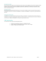
Please carefully install the cable connector into the connector housing on the MXH832 adapter card. Cable
pot 1 is located at the top of the PCIe bracket, ref Figure 1 PCIe Bracket to the right. To install the cable,
match the cable house with the connector on the MXH832 adapter card. Use even pressure to insert the
connector until it is secure. Adhere to ESD guidelines when installing the cables to ensure you don’t damage
the board. Computer cables should always use strain relief to protect the connected equipment from
excessive force on the cable. This is especially important for cables between racks. Note that for wider than
x4 connections, the same cable-ports (ie port 1 through 4) should be used on both host and target for each
individual cable, to ensure that the cards properly link up as x8 or x16.
Figure 1 PCIe
Bracket

MXH832 User’s Guide – Dolphin Interconnect Solutions Page 10
Supported cable lengths
The MXH832 supports both copper and active optical cables (AOC). Project targets can be found in Table 1 below. Long cable
qualification is in progress, please contact Dolphin for details. The max distance may change when connecting to other PCIe
products.
Cable
Speed
Distance
Copper MiniSAS-HD
Gen3
9 meters
Copper MiniSAS-HD
Gen1
12 meters
Copper PCIe 3.0 cable
Gen3
TBD
Fiber optic (AOC)
Gen3
TBD
Table 1: Cable Specifications
Disconnecting the Cable
Please carefully pull the release tab to release the cable from the locking latches and gently pull the cable out of the connector
guides.
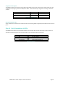
Step 6 - Verify Installation & LEDs
The MXH832 comes with 4 bi-color LEDs which show the corresponding cable port status according to Table 2: LED below.
The LEDs are visible through cut-outs in the PCIe bracket on each side of the cable connector block.
LED color
Function
Off
No cable installed
Yellow
Cable installed, no link
Green
Cable installed, link gen 3
Green blinking
Cable installed, link gen 1/2
Table 2: LED behavior

MXH832 User’s Guide – Dolphin Interconnect Solutions Page 11
Operation
Configuration and DIP Switches
The MXH832 has one bank of 8 DIP switches. The default factory setting for the MXH832 is Transparent Host mode, single (up to
x16) link connection.
The MXH832 has DIP switches for setting special modes or operations, the meaning of each DIP switch depends on the loaded
firmware. Please carefully read the documentation shipped with the card before modifying any DIP switch settings. Please pay
close attention to ON and OFF positions written on the DIP switch.
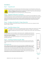
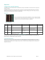
DIP Switches
Figure 2: DIP Switch shows the DIP switch for the MXH832. It is used to configure the adapter
card. Please leave all undocumented DIP switches in the default position. Table 3: DIP Switch
settings shows all the various DIP switch settings for the MXH832.
DIP no.
Name
Description
ON
OFF
Default
1-5
OPT1-5
Configuration selector, details
below
OFF
6
OPT6
CMI Disable
Will disable the CMI
interface.
CMI will be used if a PCIe
3.0 cable is detected
OFF
7
URES
Holds the management processors
in reset
Board management is
held in reset
Normal operation
OFF
8
SAFE
Enables the card to boot if the
EEPROM has been corrupted
Safe EEPROM
Normal operation
OFF
Table 3: DIP Switch settings
Note: DIP switch configuration options may be changed in the future versions. Please always consult the latest user
guide for details. The table above is valid for version 12.
Target Card Clocking Option
When the card is used in Transparent Target configuration, the default configuration settings will enable the card to provide a
reference clock on the edge connector pins 13A + 14A. To enable compatibility with some expansion backplanes, the card can also
optionally provide the reference clock on edge connector pins 6A + 7A. Please consult your backplane vendor to determine the
backplane requirements.
Figure 2: DIP Switch

MXH832 User’s Guide – Dolphin Interconnect Solutions Page 12
DIP switch Settings
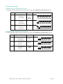
DIP Switch settings for MXH832 Host operation
The following DIP Switch settings should be considered when configuring the MXH832 for Transparent Host operation:
Use Case
Configuration MXH832 Host
DIP ON
DIP switch view
A+D
Transparent Host
One x16 port
(P1+P2+P3+P4)
(all off)
(Shipping
Default)
B
Transparent Host
Two x8 ports
(P1+P2, P3+P4)
OPT-1
C
Transparent Host
Four x4 ports
(P1,P2,P3,P4)
OPT-2
DIP Switch settings for MXH832 Target operation
The following DIP Switch settings should be considered when configuring the MXH832 for Transparent Target operation:
Use Case
Configuration MXH832 Target
DIP ON
DIP switch view
A
Transparent Target
One x16 port
(P1+P2+P3+P4)
OPT-1
OPT-2
B
Transparent Target
One x8 port
(P1+P2)
OPT-1
OPT-2
C
Transparent Target
One x4 port
(P1 or P4)
OPT-1
OPT-2

MXH832 User’s Guide – Dolphin Interconnect Solutions Page 13
Transparent Use Cases
The MXH832 card may be used as both a Host card and a Target card. A Host and Target card can be used as a pair or the Host card
can be used with a compliant Target device. The supported use cases and the DIP switch settings are summarized in section
Configuration and DIP Switches on page 11.
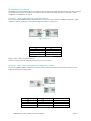
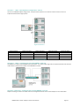
Use Case A - 1 Host – Single Expansion Configuration PCIe x16
The Host system has a MXH832 adapter configured for Host operation and a direct x16 link to a MXH832 configured for Target
operation. If you only need a x8 or x4 link, please configure according to use case B or C.
Host card ports
Target card ports
P1
P1
P2
P2
P3
P3
P4
P4
Table 4: Required x16 cabling
Always connect a cable from Port #x to Port #x
A failure connecting any of the cables will cause the link to re-train to x8 or x4.
Use Case B – 1 Host – Single or Dual Expansion Configuration – PCIe x8
The host has a MXH832 adapter configured for Transparent Host operation and a direct x8 link is used to connect one or two
independent downstream target systems.
Host card ports
Target card 1 ports
Target card 2 ports
P1
P1
P2
P2
P3
P1
P4
P2
Table 5: Required x8 cabling
Figure 3: Use Case A

MXH832 User’s Guide – Dolphin Interconnect Solutions Page 14
Use Case C – 1 Host - Quad Expansion Configuration – PCIe x4
The host has a MXH832 adapter configured for Transparent Host operation and 1-4 direct x4 links is used to connect 1-4
independent downstream target systems.
Host card ports
Target card 1 port
Target card 2 port
Target card 3 port
Target card 4 port
P1
P1
P2
P1
P3
P1
P4
P1
Table 6: Required x4 cabling
Use Case D – 1 Host – Transparent fan-out using MXS824 - PCIe x16
The MXH832 is compliant to the MXS824 24 port PCIe switch. The switch enables large-scale Transparent PCIe fanout to hundreds
of PCIe devices. Please find more details in the MXS824 Users Guide.
Use Case E – Multi Host – Transparent fan-out using MXS824 - PCIe x16
Dolphin is working on solutions to enable multi host sharing of PCIe devices. Please contact Dolphin for more information.
Figure 4: Use Case C

MXH832 User’s Guide – Dolphin Interconnect Solutions Page 15
EEPROM and Firmware Upgrade
The MXH832 design uses a microcontroller to implement the PCIe CMI protocol and other maintenance functions. Dolphin may
from time to time publish updated firmware for the microcontroller or EEPROM data for the card. Please contact Dolphin for
instructions on how to upgrade the MXH832. Please note that standard Microsemi firmware tools cannot be used to upgrade the
firmware.
Identifying the Card
The card has a label-sticker with the serial number in the format ‘MXH832-YY-ZZZZZZ’, where YY denotes the card revision (e.g. BB)
and ZZZZZZ denotes the serialized production number (e.g. 012345) – this whole string makes up the serial number of the card (i.e.
MXH832-BB-012345).
You can also get this information using lspci in Linux:
First, identify the devices for the Dolphin Host card:
# lspci | grep “Device 8532”
01:00.0 PCI bridge: PMC-Sierra Inc. Device 8532
01:00.1 Memory controller: PMC-Sierra Inc. Device 8532
02:00.0 PCI bridge: PMC-Sierra Inc. Device 8532

MXH832 User’s Guide – Dolphin Interconnect Solutions Page 16
Then run lspci and identify the card. It will show up as something like
Second,
do
# lspci -s 1:0.0 -v
01:00.0 PCI bridge: PMC-Sierra Inc. Device 8532 (prog-if 00 [Normal decode])
Flags: bus master, fast devsel, latency 0, IRQ 25
Bus: primary=01, secondary=02, subordinate=03, sec-latency=0
I/O behind bridge: 00002000-00002fff
Prefetchable memory behind bridge: 00000000df200000-00000000df3fffff
Capabilities: [40] Express Upstream Port, MSI 00
Capabilities: [7c] MSI: Enable+ Count=1/8 Maskable- 64bit+
Capabilities: [8c] Power Management version 3
Capabilities: [94] Subsystem: Dolphin Interconnect Solutions AS Device 0832
Capabilities: [100] Advanced Error Reporting
Capabilities: [138] Power Budgeting <?>
Capabilities: [148] #12
Capabilities: [178] #19
Capabilities: [1a4] Device Serial Number 00-00-42-42-00-00-00-ff
Capabilities: [1b0] Latency Tolerance Reporting
Capabilities: [1b8] Access Control Services
Capabilities: [7f8] Vendor Specific Information: ID=ffff Rev=1 Len=808 <?>
Kernel driver in use: pcieport
Kernel modules: shpchp
# lspci -s 1:0.1 -v
01:00.1 Memory controller: PMC-Sierra Inc. Device 8532
Subsystem: Dolphin Interconnect Solutions AS Device 0832
Flags: bus master, fast devsel, latency 0
Memory at f7800000 (64-bit, non-prefetchable) [size=4M]
Capabilities: [40] MSI: Enable- Count=1/4 Maskable- 64bit+
Capabilities: [50] MSI-X: Enable- Count=4 Masked-
Capabilities: [5c] Power Management version 3
Capabilities: [64] Express Endpoint, MSI 00
Capabilities: [100] Advanced Error Reporting
Capabilities: [138] Device Serial Number 00-00-42-42-00-00-00-ff
Capabilities: [144] Access Control Services
# lspci -s 2:0.0 -v
02:00.0 PCI bridge: PMC-Sierra Inc. Device 8532 (prog-if 00 [Normal decode])
Flags: bus master, fast devsel, latency 0, IRQ 26
Bus: primary=02, secondary=03, subordinate=03, sec-latency=0
I/O behind bridge: 00002000-00002fff
Prefetchable memory behind bridge: 00000000df200000-00000000df3fffff
Capabilities: [40] Express Downstream Port (Slot+), MSI 00
Capabilities: [7c] MSI: Enable+ Count=1/8 Maskable- 64bit+
Capabilities: [8c] Power Management version 3
Capabilities: [94] Subsystem: Dolphin Interconnect Solutions AS Device 0832
Capabilities: [100] Advanced Error Reporting
Capabilities: [138] Power Budgeting <?>
Capabilities: [148] #12
Capabilities: [178] #19
Capabilities: [1a4] Device Serial Number 00-00-42-42-00-00-00-ff
Capabilities: [1b0] Downstream Port Containment
Capabilities: [1bc] Access Control Services
Capabilities: [7f8] Vendor Specific Information: ID=ffff Rev=1 Len=808 <?>
Kernel driver in use: pcieport
Kernel modules: shpchp

MXH832 User’s Guide – Dolphin Interconnect Solutions Page 17
This shows the card as revision 0x4242 (hexadecimal values of the ‘BB’ letters in the ASCII table), with the production number
0x000000ff (00000255 in decimal).
Support
More information about the product, support and software downloads are available at http://www.dolphinics.com/mx.html.
Please email pci-support@dolphinics.com if you have any questions.
# lspci -s 1:0.0 -v | grep -E "Subsystem|Serial"
Capabilities: [a4] Subsystem: Dolphin Interconnect Solutions AS Device 0832
Capabilities: [100] Device Serial Number 00-00-42-42-00-00-00-ff

MXH832 User’s Guide – Dolphin Interconnect Solutions Page 18
Technical Information
Board revision history
The following table gives a general overview of the hardware revision history.
Adapter card revision
Capabilities
MXH832-CE
• Initial product version
MXH832-CF
• New improved heat sink with better mounting.
• Current shipping version.
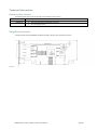
Simplified schematics
The figure below shows the MXH824 simplified schematics. Only the main functions are shown.
Figure 5: MXH832 Simplified Schematics

MXH832 User’s Guide – Dolphin Interconnect Solutions Page 19
PCIe Cable Port Signals
The external PCI Express SFF-8644 cable connector supports the following signals:
• PETpN/PETnN: PCI Express Transmitter pairs, labeled where N is the Lane number (starting with 0); “p” is the true signal
while “n” is the complement signal.
• PERpN/PERnN: PCI Express Receiver pairs, labeled where N is the Lane number (starting with 0); “p” is the true signal
while “n” is the complement signal.
• PWR: Power to support AOC and signal conditioning components within the cable assembly.
• MGTPWR: Power supplied to the connector for cable management components that are needed while the link is not
active. This needs to be active if the subsystem has power.
• CBLPRSNT#: Cable present detect, an active-low signal pulled-down by the cable when it is inserted into the MXH832
connector.
• CADDR: Signal used to configure the upstream cable management device address.
• CINT#: Signal asserted by the cable assembly to indicate a need for service via the CMI controller.
• CMISDA: Management interface data line. Used for both initial link setup and sideband messages when used with CMI
compliant cables.
• CMISCL: Management interface clock line. Used for both initial link setup and sideband messages when used with CMI
compliant cables.
External PCIe x4 Cable Connector Pin-Out
Column
Row
9
8
7
6
5
4
3
2
1
D
GND
PETn2
PETp2
GND
PETn1
PETp1
GND
MGTPWR
PWR
C
GND
PETn3
PETp3
GND
PETn0
PETp0
GND
CMISDA
CMISCL
B
GND
PERn2
PERp2
GND
PERn1
PERp1
GND
CBLPRSNT#
PWR
A
GND
PERn3
PERp3
GND
PERn0
PERp0
GND
CINT#
CADDR
Table 7; External PCIe x4 cable Pin-Out
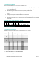
PCIe Cable Port Mapping
The MXH832 card have a quad SFF-8644 connector. The table below show the signal / port map.
Table 8 : PCIe Cable Port Mapping
Cable Port x16 Dual x8 Quad x4 PCIe 3.0 Cable Pin
L0 L0 L0 TX0/RX0
L1 L1 L1 TX1/RX1
L2 L2 L2 TX2/RX2
L3 L3 L3 TX3/RX3
L4 L4 L0 TX0/RX0
L5 L5 L1 TX1/RX1
L6 L6 L2 TX2/RX2
L7 L7 L3 TX3/RX3
L8 L0 L0 TX0/RX0
L9 L1 L1 TX1/RX1
L10 L2 L2 TX2/RX2
L11 L3 L3 TX3/RX3
L12 L4 L0 TX0/RX0
L13 L5 L1 TX1/RX1
L14 L6 L2 TX2/RX2
L15 L7 L3 TX3/RX3
Lx – PCIe lane X, Cable port is ref PCIe bracket marking
1
2
3
4

MXH832 User’s Guide – Dolphin Interconnect Solutions Page 20
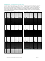
MXH832 PCIe x16 Edge Connector Pin-Out
The MXH832 Edge connector follows PCI Express CEM Specification, Rev. 3.0 section 6 – Card Connector Specification. Signal names
are shown in Table 9. In host mode, the MXH832 is PCIe SIG compliant. The signals in bold are bi-directional, where the direction
depends on if the card is configured for host or target mode. In the case where the MXH832 is configured as a target adapter in an
expansion chassis, it will provide a 100 MHz, non-SSC, reference clock on the REFCLK+/REFCLK- pins. The shaded signals TDI and
TDO are normally tri-stated, but can be configured to provide an alternative 100 MHz, non-SSC, reference clock for PCIe expansion
chassis utilizing these pins instead.
Pin
Side B
Note
Side A
Note
1
+12
PRSNT1#
2
+12
+12
3
+12
+12
12
4
GND
GND
5
SMCLK
BMC
TCK
NC
6
SMDAT
BMC
TDI
O Ref clock
+
7
GND
TDO
O Ref clock -
8
+3,3V
PWR
TMS
NC
9
TRST#
NC
+3,3
PWR
10
+3,3V aux
Standby
PWR
+3,3
PWR
11
WAKE#
Wake up
PERST#
Reset
12
NC
GND
13
GND
REFCLK+
Ref clock +
14
PERp0
REFCLK-
Ref clock -
15
PERn0
GND
16
GND
PETp0
17
PRSNT2#
PETn0
18
GND
GND
19
PERp1
NC
20
PERn1
GND
21
GND
PETp1
22
GND
PETn1
23
PERp2
GND
24
PERn2
GND
25
GND
PETp2
26
GND
PETn2
27
PERp3
GND
28
PERn3
GND
29
GND
PETp3
30
NC
PETn3
31
PRSNT2#
GND
32
GND
NC
33
PERp4
NC
34
PERn4
GND
35
GND
PETp4
36
GND
PETn4
37
PERp5
GND
38
PERn5
GND
39
GND
PETp5
40
GND
PETn5
41
PERp6
GND
42
PERn6
GND
43
GND
PETp6
Pin
Side B
Note
Side A
Note
44
GND
PETn6
45
PERp7
GND
46
PERn7
GND
47
GND
PETp7
48
PRSSNT2#
PETn7
49
GND
GND
50
PERp8
NC
51
PERn8
GND
52
GND
PETp8
53
GND
PETn8
54
PERp9
GND
55
PERn9
GND
56
GND
PETp9
57
GND
PETn9
58
PERp10
GND
59
PERn10
GND
60
GND
PETp10
61
GND
PETn10
62
PERp11
GND
63
PERn11
GND
64
GND
PETp11
65
GND
PETn11
66
PERp12
GND
67
PERn12
GND
68
GND
PETp12
69
GND
PETn12
70
PERp13
GND
71
PERn13
GND
72
GND
PETp13
73
GND
PETn13
74
PERp14
GND
75
PERn14
GND
76
GND
PETp14
77
GND
PETn14
78
PERp15
GND
79
PERn15
GND
80
GND
PETp15
81
PRSNT2#
PETn15
82
NC
GND
Table 9: PCIe Edge Connector Pin-Out
Page is loading ...
Page is loading ...
-
 1
1
-
 2
2
-
 3
3
-
 4
4
-
 5
5
-
 6
6
-
 7
7
-
 8
8
-
 9
9
-
 10
10
-
 11
11
-
 12
12
-
 13
13
-
 14
14
-
 15
15
-
 16
16
-
 17
17
-
 18
18
-
 19
19
-
 20
20
-
 21
21
-
 22
22


Dolphin MXH832 Adapter User guide
- Category
- Network switches
- Type
- User guide
Ask a question and I''ll find the answer in the document
Finding information in a document is now easier with AI
Related papers
-
Dolphin MXH932 Adapter User manual
-
-
-
-
-
-
-
-
-
Other documents
-
 One Stop Systems OSS-PCIE-CBL-X4-3M Datasheet
-
 One Stop Systems OSS-PCIE-CBL-X16-1M Datasheet
-
 One Stop Systems OSS-PCIE-HIB25-X1-T Datasheet
-
One Stop Systems OSS-PCIe-HIB38-x16-T User manual
-
Mircom LT-978 RB-MD-955 TX3-ER-8 Installation guide
-
 Netstor NA265A-G4 User manual
-
Crestron HD-EXT3-C User guide
-
 One Stop Systems OSS-PCIE-HIB2-EC-X4 User manual
-
3M High-Routability Internal HD MiniSAS Cable Assemblies, 8U Series Important information
-
 One Stop Systems OSS-PCIE-HIB25-X4-H User manual


