Dolphin MXH830 Adapter User guide
- Category
- Network switches
- Type
- User guide
Dolphin MXH830 Adapter
The MXH830 is a versatile and powerful low profile, half-length PCIe adapter designed for a wide range of applications in high-performance computing (HPC) and data-intensive environments.
Capabilities:
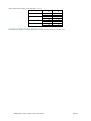
- NTB and Transparent Bridge Modes: Supports Non-Transparent Bridging (NTB) for ultra-low latency and high-bandwidth communication between nodes in a cluster, and Transparent Bridge mode for connecting devices to a PCIe switch or root complex.
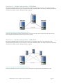
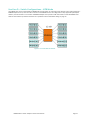
- Multi-Node Configurations: Enables the connection of multiple nodes in 2, 3, and 5 node configurations, making it suitable for building scalable and cost-effective clusters.
Dolphin MXH830 Adapter
The MXH830 is a versatile and powerful low profile, half-length PCIe adapter designed for a wide range of applications in high-performance computing (HPC) and data-intensive environments.
Capabilities:
- NTB and Transparent Bridge Modes: Supports Non-Transparent Bridging (NTB) for ultra-low latency and high-bandwidth communication between nodes in a cluster, and Transparent Bridge mode for connecting devices to a PCIe switch or root complex.
- Multi-Node Configurations: Enables the connection of multiple nodes in 2, 3, and 5 node configurations, making it suitable for building scalable and cost-effective clusters.


-
 1
1
-
 2
2
-
 3
3
-
 4
4
-
 5
5
-
 6
6
-
 7
7
-
 8
8
-
 9
9
-
 10
10
-
 11
11
-
 12
12
-
 13
13
-
 14
14
-
 15
15
-
 16
16
-
 17
17
-
 18
18
-
 19
19
-
 20
20
-
 21
21


Dolphin MXH830 Adapter User guide
- Category
- Network switches
- Type
- User guide
Dolphin MXH830 Adapter
The MXH830 is a versatile and powerful low profile, half-length PCIe adapter designed for a wide range of applications in high-performance computing (HPC) and data-intensive environments.
Capabilities:
- NTB and Transparent Bridge Modes: Supports Non-Transparent Bridging (NTB) for ultra-low latency and high-bandwidth communication between nodes in a cluster, and Transparent Bridge mode for connecting devices to a PCIe switch or root complex.
- Multi-Node Configurations: Enables the connection of multiple nodes in 2, 3, and 5 node configurations, making it suitable for building scalable and cost-effective clusters.
Ask a question and I''ll find the answer in the document
Finding information in a document is now easier with AI
Related papers
Other documents
-
 One Stop Systems OSS-PCIE-CBL-X16-1M Datasheet
-
 One Stop Systems OSS-PCIE-CBL-X4-3M Datasheet
-
3M High Routability Internal MiniSAS HD Cable Assembly, Shortened Connector, 8U Series User guide
-
Mircom LT-978 RB-MD-955 TX3-ER-8 Installation guide
-
Crestron HD-EXT3-C User guide
-
One Stop Systems OSS-PCIe-HIB38-x16-T User manual
-
 One Stop Systems OSS-PCIE-HIB2-EC-X4 User manual
-
-
 Netstor NA265A-G4 User manual
-
Westermo ODW-730-F2 User guide


