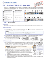
Extron DTP CrossPoint 84 User manual

Category
Video switches
Type
User manual
68-2349-50 Rev. E
01 20
DTP CrossPoint 84
Scaling Presentation Matrix Switchers with DTP Extension
Matrix Switchers
IMPORTANT:
IMPORTANT:
Refer to www.extron.com for the complete
user guide, installation instructions, and
specifications before connecting the
product to the power source.
IMPORTANT:
IMPORTANT:
Refer to www.extron.com for the complete
user guide, installation instructions, and
specifications before connecting the
product to the power source.
Setup Guide
Safety Instructions
NOTE: For more information on safety guidelines, regulatory compliances,
EMI/EMF compatibility, accessibility, and related topics, see the “Extron Safety and
Regulatory Compliance Guide” on the Extron website.
Copyright
© 2014-2020 Extron Electronics. All rights reserved. www.extron.com
Trademarks
All trademarks mentioned in this guide are the properties of their respective owners.
The following registered trademarks, registered service marks, and trademarks are the
property of RGB Systems, Inc. or Extron Electronics (see the current list of trademarks on
the Terms of Use page at www.extron.com):
Registered Trademarks
(®)
EExtron, Cable Cubby, ControlScript, CrossPoint, DTP, eBUS, EDID Manager,
EDID Minder, FlatField, FlexOS, Glitch Free, GlobalConfigurator, Global Scripter,
GlobalViewer, Hideaway, HyperLane, HyperLane, IPIntercom, IPLink, KeyMinder,
LinkLicense, LockIt, MediaLink, MediaPort, NetPA, PlenumVault, PoleVault, PowerCage,
PURE3, Quantum, ShareLink, Show Me, SoundField, SpeedMount, SpeedSwitch,
StudionStation, SystemINTEGRATOR, TeamWork, TouchLink, V‑Lock, VersaTools,
VN‑Matrix, VideoLounge, VoiceLift, WallVault, WindoWall, XPA, XTP, XTPSystems, and
ZipClip
Registered Service Mark
(SM)
: S3 Service Support Solutions
Trademarks
(
)
AAP, AFL (Accu‑RATEFrameLock), ADSP(Advanced Digital Sync Processing),
Auto‑Image, AVEdge,CableCover, CDRS(ClassDRippleSuppression), DDSP(Digital
Display Sync Processing), DMI (DynamicMotionInterpolation), DriverConfigurator,
DSPConfigurator, DSVP(Digital Sync Validation Processing), eLink, EQIP, EverLast,
FastBite, Flex55, FOX, FOXBOX, IP Intercom HelpDesk, MAAP, MicroDigital, Opti‑
Torque, PendantConnect, ProDSP, QS‑FPC(QuickSwitch Front Panel Controller), Room
Agent, Scope‑Trigger, SIS, SimpleInstructionSet, Skew‑Free, SpeedNav, Triple‑Action
Switching, True4K, True8K, Vector™ 4K, WebShare, XTRA, and ZipCaddy
 
FCC Class A Notice
This equipment has been tested and found to comply with the limits for a
Class A digital device, pursuant to part15 of the FCC rules. The ClassA
limits provide reasonable protection against harmful interference when
the equipment is operated in a commercial environment. This equipment
generates, uses, and can radiate radio frequency energy and, if not
installed and used in accordance with the instruction manual, may cause
harmful interference to radio communications. Operation of this equipment
in a residential area is likely to cause interference. This interference must be
corrected at the expense of the user.
ATTENTION: The Twisted Pair Extension technology works with
unshielded twisted pair (UTP) or shielded twisted pair (STP) cables;
but to ensure FCC Class A and CE compliance, STP cables and STP
Connectors are required.
For more information on safety guidelines, regulatory compliances,
EMI/EMF compatibility, accessibility, and related topics, see the
Extron Safety and Regulatory Compliance Guide” on the Extron
website.
Conventions Used in this Guide
Notifications
ATTENTION:
Risk of property damage.
Risque de dommages matériels.
NOTE: A note draws attention to important information.
Software Commands
Commands are written in the fonts shown here:
^AR Merge Scene,,Op1 scene 1,1 ^B 51 ^W^C
[01]
R
0004
00300
00400
00800
00600
[02]
35
[17]
[03]
E X! *X1&* X2)* X2#* X2! CE}
NOTE: For commands and examples of computer or device
responses mentioned in this guide, the character “0” is used for the
number zero and “O” is the capital letter “o.”
Computer responses and directory paths that do not have variables are
written in the font shown here:
Reply from 208.132.180.48: bytes=32 times=2ms TTL=32
C:\Program Files\Extron
Variables are written in slanted form as shown here:
ping xxx.xxx.xxx.xxx —t
SOH R Data STX Command ETB ETX
Selectable items, such as menu names, menu options, buttons, tabs, and
eld names are written in the font shown here:
From the File menu, select New.
Click the OK button.
Specifications Availability
Product specications are available on the Extron website,
www.extron.com.
Extron Glossary of Terms
A glossary of terms is available at http://www.extron.com/technology/
glossary.aspx.
DTP CrossPoint 84 • Contents vii
Introduction .............................. 1
About this Guide ........................... 1
About the DTP CrossPoint
Matrix Switchers .......................... 1
DTP Input and Output Signals .. 3
Installation ................................ 4
Rear Panel ..................................... 4
Video Inputs and Outputs ......... 5
Audio Inputs and Outputs ......... 6
Serial and IR Insertion
Connections ............................. 7
Control Connections ................. 7
Switcher Reset .......................... 8
Power ........................................ 8
Additional Connector
Information ............................... 9
Front Panel .................................. 14
Front Panel Operations ......... 15
Creating a Tie .............................. 15
Recalling a Preset ....................... 16
Viewing Ties (and Muting
Outputs) ..................................... 16
Viewing and Adjusting Volume
and Mic Volume ......................... 16
Setting the Front Panel Locks
(Executive Modes) ..................... 17
Selecting Lock Mode 2 or
Toggling Between Mode 2
and Mode 0 ............................ 17
Selecting Lock Mode 2 or
Toggling Between Mode 2
and Mode 1 ............................ 18
Remote Control ..................... 19
Selected SIS Commands ............ 19
Establishing a Network
(Ethernet) Connection ............ 19
Number of Connections .......... 20
Establishing a USB Port
Connection ............................. 20
Host-to-Switcher
Instructions ............................. 20
Common SIS Command
Symbols ................................. 20
SIS Command and Response
Table for Matrix Switcher
Commands ............................. 21
Installing and Starting the
Control Programs ....................... 26
Installing the programs ............ 26
Starting the Product
Conguration Software .......... 28
Starting the DSP Congurator
Program .................................. 29
Accessing the HTML Pages ........ 31
Contents
DTP CrossPoint 84 • Contentsviii
DTP CrossPoint 84 • Introduction 1
Introduction
This section gives an overview of the Extron DTP CrossPoint 84 Series
matrix switchers and describes their features. Topics that are covered
include:
About this Guide
About the DTP Cr
ossPoint Matrix Switchers
About this Guide
NOTE: For more information on subjects in this guide, see the DTP
CrossPoint 84 Series User Guide and the IPCP Pro Series User Guide
available at www.extron.com.
This guide provides instructions for an experienced installer to set up
and operate the Extron DTP CrossPoint 84 Scaling Presentation Matrix
Switchers with DTP Extension. Step by step instructions show you how to:
Connect the har
dware (see Installation on page4)
Perform basic operations (see
Front Panel Operations on page15)
Use both the front panel controls and selected Simple Instruction Set
(SIS) commands (see Front Panel Operations on page15 and SIS
Command and Response Table for Matrix Switcher Commands on
page21)
Load and start up the Micr
osoft
®
Windows
®
-based Product
Configuration Software (see page28) and DSP Configurator
Program (see page29).
Connect to the built-in HTML pages (see page31), which you
can use to view the switcher status and make changes to the
communications protocol and set the system clock.
About the DTP CrossPoint Matrix Switchers
The DTP CrossPoint matrix switchers distribute HDCP-compliant HDMI
and Extron proprietary DTP video and audio signal types. A matrix switcher
routes any input signal to any combination of outputs. It can route multiple
input and output congurations simultaneously.
The xed matrix size switchers support a total of eight inputs: six HDMI
and two inputs from Extron DTP transmitting devices. The matrix switchers
provide four outputs: two HDMI and two scaled DTP outputs.
The DTP CrossPoint Matrix Series consists of three 8-input by 4-output
models, differentiated by their audio and control capabilities:
DTP CrossPoint 84
DTP CrossPoint 84 IPCP SA — Includes a stereo audio amplifier and
a built-in Extron IPCP Pro 350 control processor
DTP CrossPoint 84 IPCP MA 70 — Includes a 70 V mono audio
amplifier and a built-in Extron IPCP Pro 350 control processor
2 DTP CrossPoint 84 • Introduction
POWER
12V
2
--A MAX
Rx GTx RxTxG
RS-232 IR
RxTx
1
RGB, Y, R-Y, B-YHDMIHDMI
SIG LINK
DTP OUT
AUDIO
CONTACTRS-232TALLY
3
123G123+V
RESET
INPUTS
OVER DTPREMOTE
100-240V ~ --A MAX
50/60 Hz
LAN
EXP
RS-232
Tx Rx G
RESET
MIC +48V
5678
1234
8
4 1
12345G 6 78910 G
11 12 13 14 15 G1617181920G
234
56 78
910
11 127
3
6
2
5
1
MIC/LINE INPUTS
OUTPUTS
DIGITAL I/O
REMOTE
DMP 128 C
LAN
3
21
4
321
50-60 Hz
100-240V ~ 2.0 A MAX
1
L
R
SIG LINK
OUT
SIG LINK
OUT
1
3
4
4
XTP
RS-232 IR
Tx Rx Tx RxG
Tx Rx
RTSCTS
G
Tx Rx GTxRxG
RS-232 IR
RS-232 IR
Tx Rx Tx RxG
Tx Rx G
Tx Rx Tx Rx
XTP
RESET
S/PDIF
OUT
DTP
XTP
DTP
XTP
DTP
EXP
+48V
MIC/LINE
1
1
3
2
4
2
3
4
LINK
LAN 2
LAN 1
LAN 3
HDBT
G
DTP
HDBT
2
1234
5
7
8
6
DTP CROSSPOINT 84
4
CLASS 2 WIRING
8/
R
RS-232 IR
Tx
Rx
Tx RxG
OVER TP
OVER TP
REMOTE
SIG LINK
IN
SIG LINK
IN
AUDIO INPUTS
INPUTS
AUDIO OUTPUTS
AMP OUTPUT
COM1
CONTROL
1234G
COM2 DIGITAL I/O
COM3
S
DMP EXPANSION
SGG
1
1
2
2
C34C
D-SG+S+V
IR/SERIAL
PWR OUT = 6W
eBUS
RELAYS
OUTPUTS
1
LR
1
LR
3
LR
3
LR
5
LR
2
LR
4
LR
2
L
R
4
L
R
6
LR
Extron Extron
OUTPUTS
AUDIO
TxRx GTxRx
RS-232 IR
OVER DTP
OUTPUTS
AUDIO
TxRx GTxRx
RS-232 IR
OVER DTP
OUTPUTS
AUDIO
TxRx GTxRx
RS-232 IR
OVER DTP
OUTPUTS
AUDIO
TxRx GTxRx
RS-232 IR
OVER DTP
DTP HDMI 230 Tx
Flat Panel DisplayFlat Panel Display
CATx Cable
up to 330' (100 m)
CATx Cable up to 230' (70 m)
CATx Cable
up to 230' (70 m)
CATx Cable
up to 330' (100 m)
RS-232HDMI
HDMI
Extron
DTP HDMI
330 D Rx
Receiver
Extron
DTP HDMI
230 D Rx
Receiver
RS-232
Ethernet
Ethernet
Audio
Audio
Audio
AudioAudio
AudioAudio
HDMI
Extron
DTP T USW 333
DTP Transmitter
Extron
DTP HDMI 230 Tx
Transmitter
Inputs
Outputs
Extron
TLP 1020T
10" Tabletop
TouchLink Pro
Touchpanel
AV
Control
Network
Microphones
Extron
SM 26
Surface Mount
Speakers
Extron
DMP 128 C
Digital Matrix
Processor
Camera
Video Conference
Codec
Table Microphones
Wireless
Microphones
Extron
DTP CrossPoint 84 SA
Scaling Presentation
Matrix Switcher with
DTP Extension
Figure 1. Typical DTP CrossPoint Application
The switchers provide four mono microphone (mic)/line level inputs that
can be mixed with or across one or all audio outputs.
The IPCP models also feature the built-in Extron IPCP Pro 350 control
processor, which has local area network (LAN) Ethernet ports, RS-232
and IR-based control, relays, and digital I/O controls that can control and
monitor a variety of external devices, such as projectors and lights. The
non-IPCP model has one Ethernet port.
The matrix switcher can be remotely controlled via an Ethernet LAN port,
a serial port, or a USB port connection using either the Extron Product
Conguration Software, DSP Congurator software, or the Simple
Instruction Set (SIS).
1
3DTP CrossPoint 84 • Introduction
DTP Input and Output Signals
The DTP inputs and outputs are proprietary signals that are created within
any of the Extron DTP Extenders systems and transmitted over a single
shielded twisted pair (STP) cable.
The DTP CrossPoint accepts DTP inputs from transmitting devices such as
the DTP T USW 333. Depending on the connected transmitting model, it
generates the DTP signal from a variety of video and audio inputs, including
HDMI, DVI, analog VGA, and embedded and analog audio. The DTP signal
can also include bidirectional RS-232 and IR control signals from the
connected transmitting and receiving devices or inserted locally, on the
DTP CrossPoint switcher.
Depending on the technology of the transmitting or receiving device,
DTP 330 or DTP 230, the TP inputs and outputs can travel up to 330 feet
(100 meters) or 230 feet (70 meters) without a loss of signal integrity.
DTP CrossPoint 84 • Installation4
Installation
This section describes installation of the DTP CrossPoint matrix switchers,
including connections and features. Topics that are covered include:
Rear Panel
Fr
ont Panel
Rear Panel
50-60 Hz
100-240V ~
2.0 A MAX
1
L
R
SIG LINK
OUT
SIG LINK
OUT
1
3
4
4
XTP
RS-232 IR
Tx Rx
RTSCTS
GTxRxG Tx Rx G
RS-232 IR
Tx Rx Tx RxG
Tx Rx Tx Rx
XTP
RESET
S/PDIF
OUT
DTP
XTP
DTP
XTP
DTP
EXP
+48V
MIC/LINE
1
1
3
2
4
2
3
4
LINK
LAN 2
LAN 1
LAN 3
HDBT
G
DTP
HDBT
2
1234
5
7
8
6
DTP CROSSPOINT 84
4
CLASS 2 WIRING
8/
R
RS-232 IR
Tx Rx Tx RxG
OVER TP
OVER TP
SIG LINK
IN
SIG LINK
IN
AUDIO INPUTS
AUDIO OUTPUTS
AMP OUTPUT
CONTROL
1234G
DIGITAL I/OCOM 3COM 2COM 1
S
DMP EXPANSION
SGG
1
1
2
2
C34C
INPUTS
-S G+S+V
PWR OUT = 6W
OUTPUTS
RS-232 IR
Tx Rx Tx RxG
1
LR
1
LR
3
LR
3
LR
5
LR
2
LR
4
LR
2
LR
4
LR
6
LR
IR/SERIAL eBUSRELAYS
Tx Rx G
REMOTE LAN
BB NN
FFEE EE QQMM SSTT KKFF
CC
BB
CCAA OO GG HH
II
JJUU
DD
PP RR
** *
Figure 2. DTP CrossPoint 84 Switcher Rear Panel
ATTENTION:
Remove system power before making all connections.
Débranchez l’alimentation du système avant de faire n’importe quelle
connexion.
NOTES:
*Actual models can have either
Q
or
R
, but not both. Models with
R
also have
either
K
or
L
.
Amp Output 1 (
L
) is on the MA version (see Amp Output 1 (MA model) on
page7). It is in the same location on the switcher as
K
, in gure2.
A
HDMI Inputs 1 through 6
B
TP (XTP/DTP)
C
TP Inputs 7 and 8
D
HDMI Inputs 1-6
E
Output TP switches
F
DTP Outputs 3 – 4
G
Audio Inputs 1 – 6
H
Mic/Line Inputs 1 – 4
I
+48 V LEDs
J
Audio Outputs 1 – 4
K
* Amp Output 1 (SA model)
L
* Amp Output 1 (MA model)
M
S/PDIF Output 4
N
DMP Expansion Port and LED
O
Over TP (Inputs 7 – 8) Ports)
P
Over TP (Outputs 3 – 4) Ports
Q
* LAN port
R
* IPCP Pro 350 processor
S
Remote Port
T
Switcher Reset button
U
Power connector
2
5DTP CrossPoint 84 • Installation
Video Inputs and Outputs
A
HDMI Inputs 1 through 6 — (see figure2 on page4)
Plug HDMI digital video (or DVI with appropriate adapters)
into these HDMI ports. See HDMI connectors on page9
to secure the connector to the board with a LockIt HDMI
Cable Lacing Bracket.
B
TP (XTP/DTP) switches, inputs 7 and 8
XTP
DTP
ATTENTION:
Position this switch BEFORE connecting the
appropriate device to the TP connector. Failure to
comply can damage the endpoint.
Positionnez le sélecteur
AVANT de connecter l’appareil
approprié au connecteur TP. Ne pas respecter cette
procédure pourrait endommager le point de connexion.
XTP position — Select if the transmitting device is an Extron
XTP matrix switcher. The input is HDMI with embedded audio plus
RS-232 and IR.
DTP position — Select if the transmitting device is an Extron DTP
device. The input is HDMI with embedded audio, analog audio,
RS-232 and IR, and remote power.
C
TP Inputs 7 and 8 — Plug compatible Extron DTP or XTP
SIG LINK
IN
signals into these RJ-45 ports using STP cables. See TP
connectors on page10 to wire the connectors.
ATTENTION:
Do not connect this port to a computer data or
telecommunications network.
Ne connectez pas ces port à des données informatiques ou
à un r
éseau de télécommunications.
SIG LINK
OUT
1
3
4
4
XTP
RS-232 IR
Tx Rx Tx Rx
XTP
S/PDIF
OUT
DTP
HDBT
G
DTP
HDBT
2
RS-232 IR
Tx Rx Tx RxG
OVER TP
OUTPUTS
SIG LINK
OUT
Figure 3. Video Output Features
D
HDMI Output 1 and 2 — Plug HDMI video displays (or DVI
with appropriate adapters) into these ports. See HDMI
connectors on page9 to secure the connector to the
board with a LockIt HDMI Cable Lacing Bracket.
E
TP (XTP/HDBT/DTP) switches, outputs 3 and 4
XTP
DTP
HDBT
ATTENTION:
Position this switch BEFORE connecting the
appropriate device to the TP connector. Failure
to comply can damage the endpoint.
Positionnez le sélecteur AVANT de connecter
l’appareil approprié au connecteur TP. Ne
pas respecter cette procédure pourrait
endommager le point de connexion.
HDMI Inputs 1-6
TP (XTP/DTP)
TP Inputs 7 and 8
3
HDMI Output 1 and 2
Output TP switches
6 DTP CrossPoint 84 • Installation
XTP position — Select if the receiving device is an Extron XTP matrix
switcher. The output is HDMI with embedded audio plus RS-232 and IR.
HDBT position — Select if the receiving device is a HDBaseT-enabled
device. The output is HDMI with embedded audio plus RS-232 and IR.
DTP position — Select if the receiving device is an Extron DTP
device. The TP output is compatible with a DTP receiving device and
consists of HDMI with embedded audio, analog audio, RS-232 and IR,
and remote power.
F
TP Outputs 3 and 4 — (see figure2 on page4) Plug
SIG LINK
OUT
compatible Extron DTP receivers, XTP matrix switchers,
or HDBaseT-enabled devices into these RJ-45 ports using
STP cables (see TP connectors on page10 to wire the
connector).
ATTENTION:
Do not connect this port to a computer data or
telecommunications network.
Ne connectez pas ces port à des données informatiques ou
à un r
éseau de télécommunications.
Audio Inputs and Outputs
4
Tx Rx G
S/PDIF
OUT
EXP
+48V
MIC/LINE
1
1
3
2
4
2
3
4
LINK
REMOTE
AUDIO INPUTS
AUDIO OUTPUTS
DMP EXPANSION
1
LR
1
LR
3
LR
3
LR
5
LR
2
LR
4
LR
2
LR
4
LR
6
LR
RESET
1
L
R
4
CLASS 2 WIRING
8/
AMP OUTPUT
Figure 4. Video Output Features
G
Audio Inputs 1 through 6 — Plug balanced or unbalanced
LR
stereo audio inputs into these 3.5 mm, 5-pole captive screw
connectors (see Local and Mic/Line audio connectors on
page13 to wire the connectors).
H
Mic/Line Inputs 1 through 4 — Plug microphones or other
mono audio inputs into these 3-pole, 3.5 mm captive screw
connectors (see Local and Mic/Line audio connectors to wire
the connectors).
I
+48 V (phantom power) LEDs — Light to indicate +48 V
phantom power is switched on via software.
J
Audio Outputs 1 through 4 — Plug audio devices such
LR
an audio amplifier or powered speakers to these 3.5 mm,
5-pole captive screw connectors (see Local and Mic/Line audio
connectors to wire the connectors).
K
Amp Output 1 (SA [stereo] model) — Plug passive,
1
L
R
4
CLASS 2 WIRING
8/
4-ohm or 8-ohm speakers to this 5 mm 4-pole captive
screw connector to receive the amplified audio from
output 1.
DTP Outputs 3 – 4
4
Audio Inputs 1 – 6
Mic/Line Inputs 1 – 4
+48 V LEDs
Audio Outputs 1 – 4
Amp Output 1 (SA model)
7DTP CrossPoint 84 • Installation
L
Amp Output 1 (MA [mono] model) — (see figure2 on
AMP OUTPUT
1
CLASS 2 WIRING
page 4) Connect passive high-impedance speakers to
this 2-pole captive sc
rew connector to receive the
amplified audio from output 1.
M
S/PDIF Output 4 — Plug a compatible device into this RCA
S/PDIF
OUT
connector with a 75-ohm digital audio cable to receive a digital
audio signal from the output 4 digital stream.
N
DMP Expansion Port and LED
EXP
LINK
Expansion Port — Plug an STP cable between this port and
the Expansion port on an optional Extron DMP 128 ProDSP
Digital Matrix Processor.
Link LED — Lights to indicate that the port is connected to a
compatible device.
Serial and IR Insertion Connections
SIG LINK
OUT
SIG LINK
IN
SIG LINK
IN
SIG LINK
OUT
1
3
4
4
XTP
RS-232 IR
RS-232 IR
Tx Rx Tx RxG
Tx Rx Tx Rx
XTP
S/PDIF
OUT
DTP
XTP
DTP
XTP
DTP
HDBT
G
DTP
HDBT
2
1234
5
8
6
RS-232 IR
Tx Rx Tx RxG
OVER TP
OVER TP
INPUTS
OUTPUTS
RS-232 IR
Tx Rx Tx RxG
Figure 5. Serial and IR Insertion Connections
O
Over TP (Inputs 7 and 8) Ports — Plug serial RS-232
RS-232 IR
Tx Rx Tx RxG
signals, modulated IR signals, or both into these 3.5 mm,
5-pole captive screw connectors to insert bidirectional
RS-232 and IR communications (see RS-232 and IR
connectors on page14 to wire the connectors).
P
Over TP (Outputs 3 and 4) Ports — Plug serial RS-232
RS-232 IR
Tx Rx Tx RxG
signals, modulated IR signals, or both into these 3.5 mm,
5-pole captive screw connectors to insert bidirectional
RS-232 and IR communications (see RS-232 and IR
connectors on page14 to wire the connectors).
Control Connections
Tx Rx
RTSCTS
GTxRxG Tx Rx G
LAN 2
LAN 1
LAN 3
R
CONTROL
1234G
DIGITAL I/OCOM 3COM 2COM 1
SSGG
1
1
2
2
C34C
-S G+S+V
PWR OUT = 6W
IR/SERIALeBUSRELAYS
Tx Rx G
REMOTE LAN
Figure 6. IPCP Control Processor and Remote Port
NOTE: Figure 6 is a composite that shows features of all models.
Specific models can have either a LAN port (item
Q
, below) or a
control processor (item
R
on page 8), but not both.
Q
LAN (Ethernet) port (non-IPCP model) — If desired, connect a
network WAN or LAN hub, a control system, or a computer to the
Ethernet RJ-45 port (see TP connectors on page10 to wire the
connector).
NOTE: The factory default IP address is 192.168.254.254.
Amp Output 1 (MA model)
5
S/PDIF Output 4
DMP Expansion Port and LED
Over TP (Inputs 7 – 8) Ports
Over TP (Outputs 3 – 4) Ports
LAN port
6
8 DTP CrossPoint 84 • Installation
R
IPCP control processor (IPCP models)—(see figure2 on page4)
The IPCP models include a built-in control processor that can
control and monitor a variety of external devices. The IPCP offers
RS-232 and IR-based control, relays, and digital I/O controls. See the
IPCP Pro Series Setup Guide, included with the switcher, to make all
connections and to congure and operate the IPCP control processor.
S
Remote Port — Plug a serial RS-232 device into the matrix
Tx Rx G
REMOTE
switcher via this 3.5 mm, 3-pole captive screw connector for
remote control of the switcher (see
RS-232 and IR connectors on page14 to wire the
connector).
Switcher Reset
T
Switcher Reset button and LED — Initiates four levels of
RESET
matrix switcher reset. For different reset levels, press and hold
the recessed button while the switcher is running or while you
power up the switcher.
See the DTP CrossPoint 84 Series User Guide, available at
www.extron.com.
Power
U
Power connector — Plug the switcher into a grounded AC source.
IPCP Pro 350 processor
Remote Port
Switcher Reset button
Power connector
9DTP CrossPoint 84 • Installation
Additional Connector Information
HDMI connectors
Use a LockIt Lacing Bracket to securely fasten each HDMI cable to the
switcher as follows.
1. Plug the HDMI cable into
3
33
11
44
55
22
the panel connection.
2. Loosen the HDMI
connection mounting screw
from the panel enough
to allow the LockIt lacing
bracket to be placed over
it. The screw does not have
to be removed.
3. Place the LockIt lacing
bracket on the screw
and against the HDMI
connector, then tighten
the screw to secure the
bracket.
ATTENTION:
Do not overtighten the HDMI connector mounting screw.
The shield it fastens to is very thin and can easily be
stripped.
Ne serrez pas trop la vis de montage du connecteur HDMI.
Le blindage auquel elle est attachée est très n et peut
facilement être dénudé
4. Loosely place the included tie wrap around the HDMI connector and
the LockIt lacing bracket as shown.
5. While holding the connector securely against the lacing bracket, use
pliers or similar tool to tighten the tie wrap, then remove any excess
length.
10 DTP CrossPoint 84 • Installation
TP connectors
All RJ-45 ports, whether DTP ports, the Expansion port, and the LAN
(Ethernet) ports on the switcher or IPCP control processor use twisted pair
cables (see gure 7).
Patch (straight) cable
DTP input and output ports
— Shielded twisted pair (STP) for
connection to Extron DTP transmitters and receivers, XTP matrix
switchers, or HDBaseT-enabled devices.
Expansion port
— STP for connection between the matrix
switcher and a DMP 128. A shielded 1-foot cable is included with
the DMP 128.
LAN ports
— Unshielded twisted pair (UTP) or STP for
connection of the LAN port to an Ethernet LAN.
Cr
ossover cable (see figure 7) —
LAN ports
— UTP or STP for direct connection between the
DTP CrossPoint 84 matrix switcher and a connected computer.
A cable that is wired as T568A at one end
and T568B at the other (Tx and Rx pairs
reversed) is a "crossover" cable.
A cable that is wired the same at both ends is
called a "straight-through" cable, because
no pin/pair assignments are swapped.
12345678
RJ-45
Connector
Inser
t Twisted
Pair Wires
Pins:
Pin
1
2
3
4
5
6
7
8
Wire color
White-green
Green
White-orange
Blue
White-blue
Orange
White-brown
Brown
Wire color
T568A T568B
End 1 End 2End 1 End 2
White-orange
Orange
White-green
Blue
White-blue
Green
White-brown
Brown
Pin
1
2
3
4
5
6
7
8
Wire color
White-orange
White-green
Blue
White-blue
White-brown
Brown
Wire color
T568BT568B
White-orange
OrangeOrange
White-green
Blue
White-blue
GreenGreen
White-brown
Brown
LAN Ports
DTP I/O Ports, Expansion Port, and LAN Ports
Crossover Cable
Straight-through Cable
Figure 7. RJ-45 Connector and Pinout Tables
NOTES:
Do not use standard telephone cables. Telephone cables do not
support Ethernet or Fast Ethernet.
Do not stretch or bend cables. Transmission errors can occur.
7
11DTP CrossPoint 84 • Installation
LAN ports
The LAN ports require Category (CAT) 3, CAT 5e, or CAT 6a unshielded
twisted pair (UTP) or shielded twisted pair (STP) cables, crossover or patch
cables.
The cable used depends on your network speed. The switcher LAN port
supports both 10 Mbps (10Base-T — Ethernet) and 100 Mbps (100Base-T
— Fast Ethernet), half-duplex and full-duplex Ethernet connections. Input
and output boards support 100Base-T only.
10Base-T Ether
net requires CAT 3 UTP or STP cable at minimum.
100Base-T Fast Ether
net requires CAT 5e UTP or STP cable at
minimum.
For ports on an IPCP module, see the
IPCP Pro Series User Guide at
www.extron.com to make all network connections and to congure and
operate the IPCP control processor.
DTP and Expansion ports
The DTP input and output ports are compatible with Extron
XTP DTP 24 SF/UTP cables, as well as CAT 5e, 6, 6a, and 7 shielded
twisted pair (F/UTP, SF/UTP, and S/FTP) cable. The Expansion port requires
CAT 5e, 6, 6a, or 7 shielded twisted pair cable.
For the Expansion port only —
ATTENTION:
Connect this port to the Expansion port on a compatible
Extron DMP processor. Do NOT connect this port to a LAN or
Power over Ethernet port; equipment damage can occur.
Connectez ce port au port d’expansion sur un processeur
DMP d’Extron compatible. Ne connectez
PAS ce port à un port
LAN ou d’alimentation via Ethernet ; le matériel pourrait être
endommagé.
12 DTP CrossPoint 84 • Installation
For the DTP ports only —
Extron recommends the following practices to achieve full transmission
distances up to 330 feet (100 m) and reduce transmission errors.
Use the following Extron XTP DTP 24 SF/UTP cables and connectors for
the best performance:
XTP DTP 24/1000
Non-Plenum 1000' (305 m) spool
22-236-03
XTP DTP 24P/1000
Plenum 1000' (305 m) spool
22-235-03
XTP DTP 24 Plug
Package of 10 101-005-02
If not using XTP DTP 24 cable, at a minimum, Extron recommends 24 AWG,
solid conductor, STP cable with a minimum bandwidth of 400 MHz.
Terminate cables with shielded connectors to the TIA/EIA T568B standard
only (patch cables, see figure7 on page10).
Limit the use of more than two pass-through points, which may include
patch points, punch down connectors, couplers, and power injectors. If
these pass-through points are required, use CAT 6 or 6a shielded couplers
and punch down connectors.
ATTENTION:
Do not connect these boards to a computer data or
telecommunications network.
Ne connectez pas ces port à des données informatiques ou à
un réseau de télécommunications.
Do not use Extron UTP23SF-4 Enhanced Skew-Free AV UTP
cable or STP201 cable to link the matrix switcher to Extron
DTP products, XTP matrix switchers, or HDBaseT-enabled
devices.
N'utilisez pas le câble AV Skew-Free UTP version améliorée
UTP23SF-4 ou le câble STP201 pour relier la grille de
commutation aux produits DTP, aux grilles de commutation
XTP ou aux appareils équipés HDBaseT Extron.
To ensure FCC Class A and CE compliance, STP cables and
STP connectors are required.
An de s’assurer de la compatibilité entre FCC ClasseA et CE,
les câbles STP et les connecteurs STP sont nécessaires.
NOTE: When using cable in bundles or conduits, consider the
following:
Do not exceed 40% ll capacity in conduits.
Do not comb the cable for the rst 20 meters, where cables are
straightened, aligned, and secured in tight bundles.
Loosely place cables and limit the use of tie wraps or hook and
loop fasteners.
Separate twisted pair cables from AC power cables.
1 / 1

Extron DTP CrossPoint 84 User manual

Category
Video switches
Type
User manual

Ask a question and I''ll find the answer in the document

Finding information in a document is now easier with AI

Ask the document