
Sitework Systems
Form No. 492-9216
Wheeled
Compact Utility Loader
Service Manual
Chain Drive / 4-Paw Gas / 4-Paw Diesel

This service manual was written expressly for Toro service technicians. The Toro Company has made every effort to
make the information in this manual complete and correct.
Basic shop safety knowledge and mechanical/electrical skills are assumed. The Table of Contents lists the systems
and the related topics covered in this manual.
For service information on drive systems, please refer to the Hydro-Gear BDP-10A/16A/21L Pump service manual
(form no. 492-4789), Hydro-Gear P Series Pump service manual (form no. BLN 52503) and Parker-Ross TF wheel
motor service manual (form no. 492-4753). For information specic to the engines used on this unit, refer to the
appropriate engine manufacturer’s service and repair instructions.
Units covered on in this manual are: Wheeled Chain Drive compact utility loader, model years 1998 - current
Wheeled 4-Paw Gas compact utility loader, model years 1999 - current
Wheeled 4-Paw Diesel compact utility loader, model years 1999 - current
The manual may also be specied for use on later model products.
The hydraulic power system is precision machinery. Maintain strict cleanliness control during all stages of service
and repair. Cover or cap all hose ends and ttings whenever they are exposed. Even a small amount of dirt or other
contamination can severely damage the system.
We are hopeful that you will nd this manual a valuable addition to your service shop. If you have any questions or
comments regarding this manual, please contact us at the following address:
The Toro Company
SWS Technical Services
8111 Lyndale Avenue South
Bloomington, MN 55420
The Toro Company reserves the right to change product specications or this manual without notice.
ABOUT THIS MANUAL
Copyright© All Rights Reserved
©2012 The Toro Company

ii Toro Wheeled CUL Service Manual
5/01/12
Revision 000 . . . . . . . . . . . . .
REVISIONS

TOC-1Toro Wheeled CUL Service Manual
TABLE OF CONTENTS
ALL UNITS SAFETY INFORMATION
General Information ...................................................................................................................1/1-1
Think Safety First.......................................................................................................................1/1-1
ALL UNITS SPECIFICATIONS
General Specications...............................................................................................................2/1-1
Dimensions ................................................................................................................................2/1-2
Engine .......................................................................................................................................2/1-3
Performance ..............................................................................................................................2/1-4
Hydraulic System.......................................................................................................................2/1-5
Electrical System .......................................................................................................................2/1-6
Drive System .............................................................................................................................2/1-6
Torque Specications ................................................................................................................2/1-7
Standard Torque for Dry, Zinc Plated, and Steel Fasteners (Inch Series) .................................2/1-8
Standard Torque for Dry, Zinc and Steel Fasteners (Metric Series) ..........................................2/1-9
Other Torque Specications ....................................................................................................2/1-10
Equivalents and Conversions .................................................................................................. 2/1-11
U.S. to Metric Conversions ......................................................................................................2/1-12
ALL UNITS GENERAL
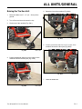
Raising the Traction Unit ............................................................................................................. 3/1-1
98-9050 Counterbalance Valve Rebuild ...................................................................................... 3/1-2
99-3040 Counterbalance Valve Rebuild ...................................................................................... 3/1-3
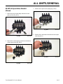
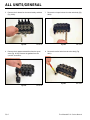
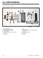
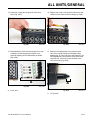
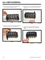
99-3070 4-Spool Valve Rebuild (Diesel) ...................................................................................... 3/1-5
99-3072 Selector Valve Rebuild ................................................................................................ 3/1-13
100-4163 Hydraulic Cylinder Rebuild ........................................................................................ 3/1-17
104-4221 Flow Divider Valve Rebuild ........................................................................................ 3/1-29
105-6246 4-Spool Valve Rebuild (Chain Drive) ......................................................................... 3/1-33
105-7867 Hydraulic Cylinder Rebuild ........................................................................................ 3/1-40
108-4710 Hydraulic Tandem Pump Rebuild .............................................................................. 3/1-50
98-4732 cross-referenced to 104-7422 4-Spool Valve Rebuild
(used on Chain Drive 22304)............................................................................................... 3/1-62
99-3077 Auxiliary Valve Rebuild ................................................................................................ 3/1-67
99-3077 Auxiliary Valve Removal........................................................................................ 3/1-67
99-3077 Auxiliary Valve Assembly ...................................................................................... 3/1-70
CHAIN DRIVE DRIVE SYSTEM
Drive Chain Replacement............................................................................................................ 4/1-1
Drive Chain Removal ............................................................................................................ 4/1-1
Drive Chain Installation ......................................................................................................... 4/1-6
Front Axle Replacement ............................................................................................................ 4/1-10
Front Axle Removal ............................................................................................................. 4/1-10
Front Axle Installation .......................................................................................................... 4/1-18
Sprocket & Wheel Hub .............................................................................................................. 4/1-28
Sprocket & Chain Inspection ............................................................................................... 4/1-28
Rear Sprocket & Wheel Hub Removal ................................................................................ 4/1-30
Sprocket Replacement ........................................................................................................ 4/1-35
Sprocket Removal ............................................................................................................... 4/1-35
Sprocket Installation ............................................................................................................ 4/1-36
Rear Sprocket & Wheel Hub Installation ............................................................................. 4/1-37
Front Sprocket & Wheel Hub Removal ............................................................................... 4/1-40
Front Axle Hub Rebuild ....................................................................................................... 4/1-46
Front Sprocket & Wheel Hub Installation ............................................................................ 4/1-48

TOC-2 Toro Wheeled CUL Service Manual
TABLE OF CONTENTS
CHAIN DRIVE DRIVE SYSTEM cont.
Checking the Drive Chain Tension ............................................................................................ 4/1-54
Adjusting the Drive Chain Tension ............................................................................................. 4/1-55
Wheel Motor Replacement ........................................................................................................ 4/1-56
Wheel Motor Removal ........................................................................................................ 4/1-56
Wheel Motor Installation ..................................................................................................... 4/1-64
CHAIN DRIVE HYDRAULICS
Counterbalance Valve Replacement ........................................................................................... 4/2-1
Counterbalance Valve Removal ............................................................................................ 4/2-1
Counterbalance Valve Installation ......................................................................................... 4/2-6
4-Spool Valve Replacement ...................................................................................................... 4/2-11
4-Spool Valve Removal ....................................................................................................... 4/2-11
4-Spool Valve Installation .................................................................................................... 4/2-17
Hydraulic Filter Head Replacement ........................................................................................... 4/2-24
Hydraulic Filter Head Removal ........................................................................................... 4/2-24
Hydraulic Filter Head Installation ........................................................................................ 4/2-26
Auxiliary Valve & Selector Valve Replacement .......................................................................... 4/2-28
Auxiliary Valve & Selector Valve Removal .......................................................................... 4/2-28
Auxiliary Valve & Selector Valve Installation ....................................................................... 4/2-31
Lift Cylinder Replacement ......................................................................................................... 4/2-35
Lift Cylinder Removal .......................................................................................................... 4/2-35
Lift Cylinder Installation ....................................................................................................... 4/2-38
Tilt Cylinder Replacement (New Style) ...................................................................................... 4/2-41
Tilt Cylinder Removal .......................................................................................................... 4/2-41
Tilt Cylinder Installation ....................................................................................................... 4/2-43
CHAIN DRIVE LOADER ARM
Loader Arm Replacement ............................................................................................................ 4/3-1
Loader Arm Removal ............................................................................................................ 4/3-1
Loader Arm Installation ......................................................................................................... 4/3-7
CHAIN DRIVE GAS ENGINE
Gas Engine Replacement............................................................................................................ 4/4-1
Gas Engine Removal ............................................................................................................ 4/4-1
Gas Engine Installation ....................................................................................................... 4/4-14
CHAIN DRIVE ELECTRICAL
Ignition Switch ............................................................................................................................. 4/5-1
Purpose ................................................................................................................................. 4/5-1
Location ................................................................................................................................ 4/5-1
How It Works ......................................................................................................................... 4/5-1
Testing ................................................................................................................................... 4/5-1
Relay ........................................................................................................................................... 4/5-2
Purpose ................................................................................................................................. 4/5-2
Location ................................................................................................................................ 4/5-2
How It Works ......................................................................................................................... 4/5-2
Testing ................................................................................................................................... 4/5-2
Fuses ........................................................................................................................................... 4/5-3
Purpose ................................................................................................................................. 4/5-3
Location ................................................................................................................................ 4/5-3
How It Works ......................................................................................................................... 4/5-3
Testing ................................................................................................................................... 4/5-3

TOC-3Toro Wheeled CUL Service Manual
TABLE OF CONTENTS
CHAIN DRIVE ELECTRICAL cont.
Auxiliary Neutral Switch ............................................................................................................... 4/5-4
Purpose ................................................................................................................................. 4/5-4
Location ................................................................................................................................ 4/5-4
How It Works ......................................................................................................................... 4/5-4
Testing ................................................................................................................................... 4/5-4
Hour Meter................................................................................................................................... 4/5-5
Purpose ................................................................................................................................. 4/5-5
Location ................................................................................................................................ 4/5-5
How It Works ......................................................................................................................... 4/5-5
Testing ................................................................................................................................... 4/5-5
Battery Replacement ................................................................................................................... 4/5-6
Battery Removal ................................................................................................................... 4/5-6
Battery Installation ................................................................................................................ 4/5-7
Electrical Schematic .................................................................................................................... 4/5-9
22311 / 22317 ....................................................................................................................... 4/5-9
4-PAW GAS DRIVE SYSTEM
Front Wheel Motor Replacement................................................................................................. 5/1-1
Front Wheel Motor Removal ................................................................................................. 5/1-1
Front Wheel Motor Installation .............................................................................................. 5/1-7
Rear Wheel Motor Replacement ............................................................................................... 5/1-13
Rear Wheel Motor Removal ................................................................................................ 5/1-13
Rear Wheel Motor Installation ............................................................................................. 5/1-20
4-PAW GAS HYDRAULICS
Left Hand Counterbalance Valve Replacement ........................................................................... 5/2-1
Left Hand Counterbalance Valve Removal ........................................................................... 5/2-1
Left Hand Counterbalance Valve Installation ........................................................................ 5/2-7
Right Hand Counterbalance Valve Replacement ...................................................................... 5/2-11
Right Hand Counterbalance Valve Removal ....................................................................... 5/2-11
Right Hand Counterbalance Valve Installation .................................................................... 5/2-18
4-PAW GAS LOADER ARM
Loader Arm Replacement ............................................................................................................ 5/3-1
Loader Arm Removal ............................................................................................................ 5/3-1
Loader Arm Installation ......................................................................................................... 5/3-7
4-PAW GAS ENGINE
Engine Replacement ................................................................................................................... 5/4-1
Engine Removal .................................................................................................................... 5/4-1
Engine Installation ............................................................................................................... 5/4-13
4-PAW GAS ELECTRICAL
Ignition Switch (P/N 103990) ....................................................................................................... 5/5-1
Purpose ................................................................................................................................. 5/5-1
Location ................................................................................................................................ 5/5-1
How It Works ......................................................................................................................... 5/5-1
Testing ................................................................................................................................... 5/5-1
Relay ........................................................................................................................................... 5/5-2
Purpose ................................................................................................................................. 5/5-2

TOC-4 Toro Wheeled CUL Service Manual
TABLE OF CONTENTS
4-PAW GAS ELECTRICAL cont.
Start Relay ................................................................................................................................... 5/5-2
Kill Relay...................................................................................................................................... 5/5-2
Location ................................................................................................................................ 5/5-2
How It Works ......................................................................................................................... 5/5-2
Testing ................................................................................................................................... 5/5-3
Fuses ........................................................................................................................................... 5/5-3
Purpose ................................................................................................................................. 5/5-3
Location ................................................................................................................................ 5/5-3
How It Works ......................................................................................................................... 5/5-4
Testing ................................................................................................................................... 5/5-4
Neutral Safety Switch .................................................................................................................. 5/5-4
Purpose ................................................................................................................................. 5/5-4
Location ................................................................................................................................ 5/5-4
How It Works ......................................................................................................................... 5/5-4
Testing ................................................................................................................................... 5/5-4
Auxiliary Neutral Switch ............................................................................................................... 5/5-5
Purpose ................................................................................................................................. 5/5-5
Location ................................................................................................................................ 5/5-5
How It Works ......................................................................................................................... 5/5-5
Testing ................................................................................................................................... 5/5-5
Hour Meter/Tachometer ............................................................................................................... 5/5-6
Purpose ................................................................................................................................. 5/5-6
Location ................................................................................................................................ 5/5-6
How It Works ......................................................................................................................... 5/5-6
Testing ................................................................................................................................... 5/5-6
Electrical Schematics .................................................................................................................. 5/5-7
22318 - 2010, 2009, 2008, 2007 ........................................................................................... 5/5-7
22318 - 2006, 2005 ............................................................................................................... 5/5-8
22312 - 2005, 2004, 2003 ..................................................................................................... 5/5-8
22312 - 2004, 2003 ............................................................................................................... 5/5-9
22305 - 2002, 2001 ............................................................................................................... 5/5-9
22305 - 2000, 1999 ............................................................................................................. 5/5-10
4-PAW DIESEL DRIVE SYSTEM
Front Wheel Motor Replacement................................................................................................. 6/1-1
Front Wheel Motor Removal ................................................................................................. 6/1-1
Front Wheel Motor Installation .............................................................................................. 6/1-7
Rear Wheel Motor Replacement ............................................................................................... 6/1-13
Rear Wheel Motor Removal ................................................................................................ 6/1-13
Rear Wheel Motor Installation ............................................................................................. 6/1-20
4-PAW DIESEL HYDRAULICS
4-Spool Valve Replacement (Diesel) ........................................................................................... 6/2-1
4-Spool Valve Removal ......................................................................................................... 6/2-1
4-Spool Valve Installation ...................................................................................................... 6/2-8
Hydraulic Auxiliary, Selector & Flow Divider Valves .................................................................. 6/2-14
Hydraulic Auxiliary, Selector & Flow Divider Valves Removal ............................................. 6/2-14
Hydraulic Auxiliary, Selector & Flow Divider Valves Installation .......................................... 6/2-20
Hydraulic Lift Cylinder Replacement (Old Style) ....................................................................... 6/2-24
Hydraulic Lift Cylinder Removal .......................................................................................... 6/2-24
Hydraulic Lift Cylinder Installation ....................................................................................... 6/2-28

TOC-5Toro Wheeled CUL Service Manual
TABLE OF CONTENTS
4-PAW DIESEL HYDRAULICS cont.
Hydraulic Tilt Cylinder Replacement (Old Style)........................................................................ 6/2-30
Hydraulic Tilt Cylinder Removal .......................................................................................... 6/2-30
Hydraulic Tilt Cylinder Installation ....................................................................................... 6/2-32
Left Hand Counterbalance Valve Replacement ......................................................................... 6/2-35
Left Hand Counterbalance Valve Removal ......................................................................... 6/2-35
Left Hand Counterbalance Valve Installation ...................................................................... 6/2-39
Right Hand Counterbalance Valve Replacement ...................................................................... 6/2-43
Right Hand Counterbalance Valve Removal ....................................................................... 6/2-43
Right Hand Counterbalance Valve Installation .................................................................... 6/2-47
Hydraulic Tandem Pump Replacement ..................................................................................... 6/2-53
Hydraulic Tandem Pump Removal ...................................................................................... 6/2-53
Hydraulic Tandem Pump Installation ................................................................................... 6/2-57
4-PAW DIESEL LOADER ARM
Loader Arm Replacement ............................................................................................................ 6/3-1
Loader Arm Removal ............................................................................................................ 6/3-1
Loader Arm Installation ......................................................................................................... 6/3-7
4-PAW DIESEL ENGINE
Engine Replacement ................................................................................................................... 6/4-1
Engine Removal .................................................................................................................... 6/4-1
Engine Installation ............................................................................................................... 6/4-26
Checking the Alternator Belt Tension ......................................................................................... 6/4-60
Fan Belt Replacement ............................................................................................................... 6/4-61
Fan Belt Removal ............................................................................................................... 6/4-61
Fan Belt Installation ............................................................................................................ 6/4-66
Fan Replacement ...................................................................................................................... 6/4-72
Fan Removal ....................................................................................................................... 6/4-72
Fan Installation .................................................................................................................... 6/4-72
Fuel Shut Down Solenoid Replacement .................................................................................... 6/4-73
Fuel Shut Down Solenoid Removal .................................................................................... 6/4-73
Fuel Shut Down Solenoid Installation ................................................................................. 6/4-74
Glow Plug Replacement ............................................................................................................ 6/4-76
Glow Plug Removal ............................................................................................................ 6/4-76
Glow Plug Installation ......................................................................................................... 6/4-77
Mufer Replacement ................................................................................................................. 6/4-77
Mufer Removal .................................................................................................................. 6/4-77
Mufer Installation ............................................................................................................... 6/4-84
Radiator Replacement ............................................................................................................... 6/4-92
Radiator Removal ............................................................................................................... 6/4-92
Radiator Installation ............................................................................................................ 6/4-97
Radiator Mount Replacement .................................................................................................. 6/4-101
Radiator Mount Removal .................................................................................................. 6/4-101
Radiator Mount Installation ............................................................................................... 6/4-102
Pump Mount Assembly Rebuild............................................................................................... 6/4-103
Fan Drive Pulley, Rubber Coupler & Flywheel Adapter Replacement ..................................... 6/4-109
Fan Drive Pulley, Rubber Coupler & Flywheel Adapter Removal ..................................... 6/4-109
Fan Drive Pulley, Rubber Coupler & Flywheel Adapter Installation .................................. 6/4-113

TOC-6 Toro Wheeled CUL Service Manual
TABLE OF CONTENTS
4-PAW DIESEL ELECTRICAL
Ignition Switch ............................................................................................................................. 6/5-1
Purpose ................................................................................................................................. 6/5-1
Location ................................................................................................................................ 6/5-1
How It Works ......................................................................................................................... 6/5-1
Testing ................................................................................................................................... 6/5-1
Relay ........................................................................................................................................... 6/5-2
Purpose ................................................................................................................................. 6/5-2
Location ................................................................................................................................ 6/5-2
How It Works ......................................................................................................................... 6/5-2
Testing ................................................................................................................................... 6/5-3
Fuses ........................................................................................................................................... 6/5-4
Purpose ................................................................................................................................. 6/5-4
Location ................................................................................................................................ 6/5-4
How It Works ......................................................................................................................... 6/5-4
Testing ................................................................................................................................... 6/5-4
Neutral Safety Switches .............................................................................................................. 6/5-5
Purpose ................................................................................................................................. 6/5-5
Location ................................................................................................................................ 6/5-5
How It Works ......................................................................................................................... 6/5-5
Testing ................................................................................................................................... 6/5-5
Auxiliary Neutral Switch ............................................................................................................... 6/5-6
Purpose ................................................................................................................................. 6/5-6
Location ................................................................................................................................ 6/5-6
How It Works ......................................................................................................................... 6/5-6
Testing ................................................................................................................................... 6/5-6
Hour Meter................................................................................................................................... 6/5-7
Purpose ................................................................................................................................. 6/5-7
Location ................................................................................................................................ 6/5-7
How It Works ......................................................................................................................... 6/5-7
Testing ................................................................................................................................... 6/5-7
Indicator Lights ............................................................................................................................ 6/5-8
Purpose ................................................................................................................................. 6/5-8
Location ................................................................................................................................ 6/5-8
Engine Oil Pressure Light ............................................................................................................ 6/5-8
Battery Light ................................................................................................................................ 6/5-8
Engine Temperature Light ........................................................................................................... 6/5-8
Glow Plug Indicator Light............................................................................................................. 6/5-8
Testing Indicator Lights ......................................................................................................... 6/5-9
Glow Controller .......................................................................................................................... 6/5-10
Purpose ............................................................................................................................... 6/5-10
Location .............................................................................................................................. 6/5-10
How It Works ....................................................................................................................... 6/5-10
Testing ................................................................................................................................. 6/5-11
Fuel Shut Down Solenoid .......................................................................................................... 6/5-12
Purpose ............................................................................................................................... 6/5-12
Location .............................................................................................................................. 6/5-12
How It Works ....................................................................................................................... 6/5-12
Testing ................................................................................................................................. 6/5-13
Troubleshooting .................................................................................................................. 6/5-13
Electrical Schematics ................................................................................................................ 6/5-14
22303 -2001, 2000, 1999 .................................................................................................... 6/5-14
22303 - 2006, 2005, 2003, 2002 ......................................................................................... 6/5-15

1/1-1Toro Wheeled CUL Service Manual
Avoid res and explosions...
Avoid spilling fuel and never smoke while working with
any type of fuel or lubricant. Wipe up any spilled fuel
or oil immediately. Never remove the fuel cap or add
fuel when the engine is running. Always use approved,
labeled containers for storing or transporting fuel and
lubricants.
Avoid asphyxiation...
Never operate an engine in a conned area without
proper ventilation.
Avoid injury from batteries...
Battery acid is poisonous and can cause burns. Avoid
contact with skin, eyes, and clothing. Battery gases can
explode. Keep cigarettes, sparks, and ames away from
the battery.
Avoid injury due to inferior parts...
Use only original equipment parts to ensure that
important safety criteria are met.
Avoid injury to bystanders...
Always clear the area of bystanders before starting or
testing powered equipment.
Avoid injury due to projectiles...
Always clear the area of sticks, rocks, or any other
debris that could be picked up and thrown by the
powered equipment.
Avoid modications...
Never alter or modify any part unless it is a factory
approved procedure.
Avoid unsafe operation...
Always test the safety interlock system after making
adjustments or repairs on the machine. Refer to the
Electrical section in this manual for more information.
This symbol means WARNING or
PERSONAL SAFETY INSTRUCTION -
read the instruction because it has to do
with your safety. Failure to comply with the
instruction may result in personal injury or
even death.
This manual is intended as a service and repair manual
only. The safety instructions provided herein are for
troubleshooting, service, and repair of the Sitework
Systems wheeled compact utility loader.
The wheeled loader and attachment operator’s manual
contain safety information and operating tips for safe
operating practices. Operator’s manuals are available on
line at www.toro.com or:
The Toro Company
Publications Department
8111 Lyndale Avenue South
Bloomington, MN 55420
SAFETY INFORMATION
General Information
Avoid unexpected starting of engine...
Always turn off the engine and disconnect the spark plug
wire(s) before cleaning, adjusting, or repair.
Avoid lacerations and amputations...
Stay clear of all moving parts whenever the engine is
running. Treat all normally moving parts as if they were
moving whenever the engine is running or has the
potential to start.
Avoid burns...
Do not touch the engine, mufer, or other components
which may increase in temperature during operation,
while the unit is running or shortly after it has been
running.
Think Safety First
!

1/1-2 Toro Wheeled CUL Service Manual
SAFETY INFORMATION
Hydraulics Safety
• Inspect all hydraulic line connectors and ttings. Make
sure all hydraulic hoses and lines are in good condition
before applying pressure to the system.
• Keep body and hands away from pin hole leaks or
nozzles that eject high pressure hydraulic uid. Use
cardboard or paper to nd hydraulic leaks. Hydraulic
uid escaping under pressure can penetrate the skin
and cause injury. Fluid accidentally injected into the
skin must be surgically removed within a few hours by a
doctor or gangrene may occur.
• Before disconnecting or performing any work on the
hydraulic system, lower the loader arm/attachment to the
ground and stop the engine so all pressure is relieved.
• Be sure you understand a service procedure before
working on the machine.

2/1-1Toro Wheeled CUL Service Manual
SPECIFICATIONS
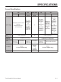
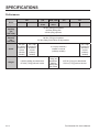
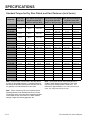
General Specications
Model
220 222 220D, 320D 322 323
22311 22317 22300
22304
22302
22303
22305 22312 22318
Spark plug
Champion Premium Gold
2071 or
Champion RC12YC
(or equivalent)
All Years:
Champion
RC12YC
(or
equivalent)
or 2001:
Champion
Premium
Gold 2071
n/a
All years:
Champion
RC12YC
(or
equivalent)
or
2001/2002:
Champion
Premium
Gold 2071
Champion
Premium
Gold 2071
or Champion
RC12YC
(or
equivalent)
Champion
Premium
Gold
2071 or
Champion
RC12YC
(or
equivalent)
or 2010:
Champion
XC12YC
(RFI type)
(or
equivalent)
Spark plug
Gap
0.030” (0.76mm) n/a 0.030” (0.76mm)
Fuel Tank
Capacity
4.0 gallon (15.1 liter)
8.0 gallon (30.2 liter) 2 tanks,
4 gallons (15.1 liters) each
Fuel
Shut-off
On the
bottom of
the fuel tank
In fuel line
near tank
On the
bottom of
the fuel tank
In fuel line
near tank
On the
bottom of
each tank
In-line near each tank
Fuel Filter
In-line
15 micron ltration rating
3 micron
ltration
rating
w/water
separator
In-line
15 micron ltration rating
Fuel Pump Vacuum pulse mechanical Vacuum pulse

SPECIFICATIONS
2/1-2 Toro Wheeled CUL Service Manual
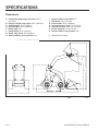
Dimensions
A. Overall operating height, fully raised / 91.2”
(2317mm)
B. Hinge pin height, fully raised / 66.0” (1676mm)
C. Overall height / 48.7” (1237mm)
D. Overall length / 82.2” (2088mm)
E. Dump angle / 34º
F. Dump height / 47.0” (1194mm)
G. Reach, fully raised / 26.0” (660mm)
H. Bucket rollback, ground position / 19º
I. Bucket rollback, fully raised / 97º
J. Wheelbase / 28.0” (711mm)
K. Overall width / 40.5” (1029mm)
X. Ground Clearance, front / 5.8” (147mm)
X. Ground Clearance, rear / 5.8” (147mm)
X. Reach, maximum / 28.0” (711mm)
X. Bucket rollback, carry position / 20º
X. = Dimension not shown
Fig A 99-8886
RELEASED Version ©Toro 2005-2005
H
G
C
F
B
A
E
I
J
D
K

SPECIFICATIONS
2/1-3Toro Wheeled CUL Service Manual
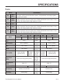
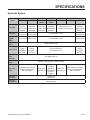
Engine
Model Specications
220
22311
22317
Kohler Command model CH20S, 4-cycle, air cooled, 2 cylinder, horizontal crank shaft, over-
head valves, 12VDC solenoid shift electric starter, 15 amp alternator and voltage regulator,
high capacity air cleaner
222
22300
22304
Kohler Command CH22, 4-cycle, air cooled 2 cylinder, horizontal crankshaft, over head valve,
hydraulic valve lifters, cast iron cylinder liners, 12VDC solenoid shift electric starter, 15 amp
alternator and voltage regulator, high capacity air cleaner
220D
320D
22302
22303
Kubota Super Mini Diesel model D722-E, High capacity dry-type remote air cleaner
322 22305
Kohler Command CH22, 4-cycle, air cooled, 2 cylinder, horizontal crankshaft, over head valve,
hydraulic valve lifters, cast iron cylinder liners, 12VDC solenoid shift electric starter, 15 amp
alternator and voltage regulator, high capacity air cleaner
323
22312
22318
Kohler Command CH23, 4-cycle, air cooled, 2 cylinder, horizontal crankshaft, over head valve,
hydraulic valve lifters, cast iron cylinder liners, 12VDC solenoid shift electric starter, 15 amp
alternator and voltage regulator, high capacity air cleaner
Model
220 222 220D, 320D 322 323
22311 22317 22300
22304
22302
22303
22305 22312 22318
Compression
Ratio
8.5:1 23.5:1 8.5:1
Displacement 38.1 in
3
(624cm
3
)
43.88 in
3
(719 cm
3
)
38.1 in
3
(624cm
3
)
41.0 in
3
(674cm
3
)
Bore 3.03” (77mm)
2.64”
(67mm)
3.03”
(77mm)
3.15” (80mm)
Stroke 2.64” (67mm)
2.68”
(68mm)
2.64” (67mm)
Power (RPM)
20 HP (14.9kW)
@ 3600 (Gross)
22 HP
(16.4kW)
@ 3600
(Gross)
20 HP
(14.9kW)
@ 3600
(Gross)
22 HP
(16.4kW)
@ 3600
(Gross)
23 HP (17.2kW)
@ 3600 (Gross)
Peak Torque
(RPM)
32 ft-lbs (43 Nm) @ 2500 (Gross)
36.8 ft-lbs
(50 Nm)
@ 2600
(Gross)
33 ft-lbs (45 Nm) @ 2500 (Gross)
No-load Speed
(RPM)
3600 ± 75
3700
+50/-100
(Installed)
3600 ± 75
Idle Speed (RPM) 1400 ± 200 1200 ± 75 1300 ± 100 1200 ± 75 1400 ± 200
Oil Capacity 2 quarts (1.9 L) with lter
0.84 US
gallons
(3.2 L)
2 quarts (1.9 L)
Dry Weight 90 lbs (41kg)
154.3 lbs
(70kg)
90 lbs (41kg)

2/1-4 Toro Wheeled CUL Service Manual
SPECIFICATIONS
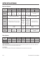
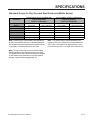
Performance
Model
220 222 220D, 320D 322 323
22311 22317 22300
22304
22302
22303
22305 22312 22318
Tip
Capacity
(per
SAE J732)
760 lbs (345kg) w/o operator
1030 lbs (467kg) with
200 lbs (91kg) operator
Operating
Capacity
(per
SAE J818)
380 lbs (172kg) w/o operator
515 lbs (234kg) with 200 lbs (91kg) operator
Speed
0-3 mph
(0-4.8km/hr)
forward or
reverse
(innitely
variable)
0-3.7 mph
(0-6.0km/hr)
forward or
reverse
(innitely
variable)
0-3 mph (0-4.8km/hr)
forward or reverse
(innitely variable)
0-3.7 mph
(0-6.0km/hr)
forward or
reverse
(innitely
variable)
Weight
1430 lbs (649kg) w/o attachment
1576 lbs (715kg) with std. bucket
1722 lbs
(781kg) w/o
attachment
1868 lbs
(847kg) with
std. bucket
1567 lbs (711kg) w/o attachment
1713 lbs (777kg) with std. bucket

2/1-5Toro Wheeled CUL Service Manual
SPECIFICATIONS
Model
220 222 220D, 320D 322 323
22311 22317 22300
22304
22302
22303
22305 22312 22318
Pressure
3000 psi
(207 bar)
system relief
pressure
3250 psi
(224 bar)
system relief
pressure
3000 psi
(207 bar)
system relief
pressure
3225 psi
(222 bar)
system relief
pressure
3000 psi (207 bar)
system relief pressure
3250 psi
(224 bar)
system relief
pressure
Low Flow
3.7 GPM
(14.0 L/min)
4.0 GPM
(15.3 L/min)
3.7 GPM (14.0 L/min)
4.0 GPM
(15.3 L/min)
High Flow
(@3600
RPM)
8.5 GPM
(32.2 L/min)
10.8 GPM
(40.9 L/min) 8.5 GPM (32.2 L/min)
10.8 GPM
(40.9 L/min)
Hydraulic
Pump
Tandem Gear Pump
Displacements
0.55 & 0.24
in
3
/rev
(9.0 &4.0
cm
3
/rev)
0.69 & 0.26
in
3
/rev
(11.2 &4.3
cm
3
/rev)
0.55 & 0.24 in
3
/rev
(9.0 &4.0 cm
3
/rev)
0.69 & 0.26
in
3
/rev
(11.2 &4.3
cm
3
/rev)
Hydraulic
Tank
Capacity
14.8 gallon (56.0 L)
Hydraulic
Filter
Spin-on 10 micron nom. Filtration rating
Hydraulic
Fluid
SAE10W-30 or 15W-40
diesel oil (API Service
CH-4 or higher)
Mobil 424
hydraulic oil
SAE10W-30
or 15W-40
diesel oil
(API Service
CH-4 or
higher)
Mobil 424
hydraulic oil
SAE10W-30 or 15W-40
diesel oil (API Service
CH-4 or higher)
Hydraulic
Cylinders
2 loader arm
1 bucket curl
Auxiliary
Connectors
Flush face type
Hydraulic System

2/1-6 Toro Wheeled CUL Service Manual
SPECIFICATIONS
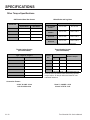
Electrical System
Model
220 222 220D, 320D 322 323
22311 22317 22300
22304
22302
22303
22305 22312 22318
Battery
12 volt,
380cca min.
@
0ºF (-18ºC)
12 volt,
340cca min.
@
0ºF (-18ºC)
12 volt,
380cca min.
@
0ºF (-18ºC)
12 volt,
435cca
@
0ºF (-18ºC)
12 volt,
380cca min.
@
0ºF (-18ºC)
12 volt, 340cca min. @
0ºF (-18ºC)
Alternator 12 VDC 15 amp with regulator
12 VDC
14.0 amp
w/regulator
12 VDC 15 amp with regulator
Interlock
Auxiliary power control lever must be
in neutral position for starting engine
Auxiliary
& traction
valves
neutral to
start
Auxiliary
power
control lever
must be
in neutral
position
for starting
engine
Auxiliary and traction
valves neutral to start
Fuses
25 amp
30 amp
30 amp
10 amp
25 amp
25 amp
30 amp
Gages
Hourmeter
on back of
control panel
Hourmeter
with service
reminder
indicator
Hourmeter
on back of
control panel
Warning
light cluster
Hourmeter
on back of
control panel
Hourmeter / tachometer
with service reminder
indicator
Drive System
Model
220 222 220D, 320D 322 323
22311 22317 22300
22304
22302
22303
22305 22312 22318
Chain Drive X X X
4-Paw X X X X
Chain Drive Models:
All four wheels are powered. The two rear wheels are individually driven by hydraulic rotor vane motors. Each front
wheel is chain driven from the rear wheels via #60H chain.
4-Paw Models:
All four wheels are powered. Each wheel is individually driven by a hydraulic roller vane motor.

2/1-7Toro Wheeled CUL Service Manual
SPECIFICATIONS
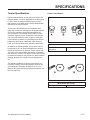
Torque Specications
Inch Series bolts and Screws
(A) Grade 1 & 2
(B) Grade 5
(C) Grade 8
Recommended fastener torque values are listed in the
following tables. For critical applications, as determined
by Toro, either the recommended torque or a torque
that is unique to the application is clearly identied and
specied in the service manual.
These torque specications for the installation and
tightening of fasteners shall apply to all fasteners which
do not have a specic requirement identied in the
service manual. The following factors shall be consid-
ered when applying torque: cleanliness of the fastener,
use of a thread sealant (Loctite), degree of lubrication
on the fastener, presence of a prevailing torque feature,
hardness of the surface underneath of the fastener’s
head, or similar condition which affects the installation.
As noted in the following tables, torque values should
be reduced by 25% for lubricated fasteners to achieve
the similar stress as a dry fastener. Torque values may
also have to be reduced when the fastener is threaded
into aluminum or brass. The specic torque value should
be determined based on the aluminum or brass material
strength, fastener size, length of thread engagement,
etc.
The standard method of verifying torque shall be per-
formed by marking a line on the fastener (head or nut)
and mating part, then back off fastener 1/4 of a turn.
Measure the torque required to tighten the fastener until
the lines match up.
Fastener Identication
Metric Bolts and Screws
(A) Class 8.8 (B) Class 10.9

2/1-8 Toro Wheeled CUL Service Manual
SPECIFICATIONS
SPECIFICATIONS
.
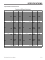
Standard Torque for Dry, Zinc Plated, and Steel Fasteners (Inch Series)
Note: Reduce torque values listed in the table above
by 25% for lubricated fasteners. Lubricated fasteners
are defined as threads coated with a lubricant such as
oil, graphite, or thread sealant such as Loctite.
Note: Torque values may have to be reduced when
installing fasteners into threaded aluminum or brass.
The specific torque value should be determined based
on the fastener size, the aluminum or base material
strength, length of thread engagement, etc.
Note: The nominal torque values listed above for
Grade 5 and 8 fasteners are based on 75% of the
minimum proof load specified in SAE J429. The
tolerance is approximately
± 10% of the nominal torque
value. Thin height nuts include jam nuts.
Thread Size
Grade 1, 5, &
8 with Thin
Height Nuts
SAE Grade 1 Bolts, Screws,
Studs, & Sems with Regular
Height Nuts (SAE J995
Grade 2 or Stronger Nuts)
SAE Grade 5 Bolts, Screws,
Studs, & Sems with Regular
Height Nuts (SAE J995
Grade 2 or Stronger Nuts)
SAE Grade 8 Bolts, Screws,
Studs, & Sems with Regular
Height Nuts (SAE J995
Grade 2 or Stronger Nuts)
In-lb In-lb N-cm In-lb N-cm In-lb N-cm
# 6 - 32 UNC
10 ± 2 13 ± 2 147 ± 23
15 ± 2 170 ± 20 23 ± 2 260 ± 20
# 6 - 40 UNF 17 ± 2 190 ± 20 25 ± 2 280 ± 20
# 8 - 32 UNC
13 ± 2 25 ± 5 282 ± 30
29 ± 3 330 ± 30 41 ± 4 460 ± 45
# 8 - 36 UNF 31 ± 3 350 ± 30 43 ± 4 31 ± 3
# 10 - 24 UNC
18 ± 2 30 ± 5 339 ± 56
42 ± 4 475 ± 45 60 ± 6 674 ± 70
#10 - 32 UNF 48 ± 4 540 ± 45 68 ± 6 765 ± 70
1/4 - 20 UNC 48 ± 7 53 ± 7 599 ± 79 100 ± 10 1125 ± 100 140 ± 15 1580 ± 170
1/4 - 28 UNF 53 ± 7 65 ± 10 734 ± 113 115 ± 10 1300 ± 100 160 ± 15 1800 ± 170
5/16 - 18 UNC 115 ± 15 105 ± 17 1186 ± 169 200 ± 25 2250 ± 280 300 ± 30 3390 ± 340
5/16 - 24 UNF 138 ± 17 128 ± 17 1446 ± 192 225 ± 25 2540 ± 280 325 ± 30 3670 ± 340
ft-lb ft-lb N-m ft-lb N-m ft-lb N-m
3/8 - 16 UNC 16 ± 2 16 ± 2 22 ± 3 30 ± 3 41 ± 4 43 ± 4 58 ± 5
3/8 - 24 UNF 17 ± 2 18 ± 2 24 ± 3 35 ± 3 47 ± 4 50 ± 4 68 ± 5
7/16 - 14 UNC 27 ± 3 27 ± 3 37 ± 4 50 ± 5 68 ± 7 70 ± 7 68 ± 9
7/16 - 20 UNF 29 ± 3 29 ± 3 39 ± 4 55 ± 5 75 ± 7 77 ± 7 104 ± 9
1/2 - 13 UNC 30 ± 3 48 ± 7 65 ± 9 75 ± 8 102 ± 11 105 ± 10 142 ± 14
1/2 - 20 UNF 32 ± 3 53 ± 7 72 ± 9 85 ± 8 115 ± 11 120 ± 10 163 ± 14
5/8 - 11 UNC 65 ± 10 88 ± 12 119 ± 16 150 ± 15 203 ± 20 210 ± 20 285 ± 27
5/8 - 18 UNF 75 ± 10 95 ± 15 129 ± 20 170 ± 15 230 ± 20 240 ± 20 325 ± 27
3/4 - 10 UNC 93 ± 12 140 ± 20 190 ± 27 265 ± 25 359 ± 34 374 ± 35 508 ± 47
3/4 - 16 UNF 115 ± 15 165 ± 25 224 ± 34 300 ± 25 407 ± 34 420 ± 35 569 ± 47
7/8 - 9 UNC 140 ± 20 225 ± 25 305 ± 34 430 ± 45 583 ± 61 600 ± 60 813 ± 81
7/8 - 14 UNF 155 ± 25 260 ± 30 353 ± 41 475 ± 45 644 ± 61 660 ± 60 895 ± 81
Standard Torque for Dry, Zinc Plated, and Steel Fasteners (Inch Series)

2/1-9Toro Wheeled CUL Service Manual
SPECIFICATIONS
SPECIFICATIONS
.
Standard Torque for Dry, Zinc, and Steel Fasteners (Metric Fasteners)
Note: Reduce torque values listed in the table above
by 25% for lubricated fasteners. Lubricated fasteners
are defined as threads coated with a lubricant such as
oil, graphite, or thread sealant such as Loctite.
Note: Torque values may have to be reduced when
installing fasteners into threaded aluminum or brass.
The specific torque value should be determined based
on the fastener size, the aluminum or base material
strength, length of thread engagement, etc.
Note: The nominal torque values listed above are
based on 75% of the minimum proof load specified in
SAE J1199. The tolerance is approximately
± 10% of
the nominal torque value. Thin height nuts include jam nuts.
Thread Size
Class 8.8 Bolts, Screws, and Studs with
Regular Height Nuts
(Class 8 or Strong Nuts)
Class 10.9 Bolts, Screws, and Studs with
Regular Height Nuts (
Class 10 or Strong Nuts)
M5 X 0.8 57 ± 5 in-lb 640 ± 60 N-cm 78 ± 7 in-lb 885 ± 80 N-cm
M6 X 1.0 96 ± 9 in-lb 1018 ± 100 N-cm 133 ± 13 in-lb 1500 ± 150 N-cm
M8 X 1.25 19 ± 2 ft-lb 26 ± 3 N-m 27 ± 2 ft-lb 36 ± 3 N-m
M10 X 1.5 38 ± 4 ft-lb 52 ± 5 N-m 53 ± 5 ft-lb 72 ± 7 N-m
M12 X 1.75 66 ± 7 ft-lb 90 ± 10 N-m 92 ± 9 ft-lb 125 ± 12 N-m
M16 X 2.0 166 ± 15 ft-lb 225 ± 20 N-m 229 ± 22 ft-lb 310 ± 30 N-m
M20 X 2.5 325 ± 33 ft-lb 440 ± 45 N-m 450 ± 37 ft-lb 610 ± 50 N-m
Standard Torque for Dry, Zinc and Steel Fasteners (Metric Series)
Page is loading ...
Page is loading ...
Page is loading ...
Page is loading ...
Page is loading ...
Page is loading ...
Page is loading ...
Page is loading ...
Page is loading ...
Page is loading ...
Page is loading ...
Page is loading ...
Page is loading ...
Page is loading ...
Page is loading ...
Page is loading ...
Page is loading ...
Page is loading ...
Page is loading ...
Page is loading ...
Page is loading ...
Page is loading ...
Page is loading ...
Page is loading ...
Page is loading ...
Page is loading ...
Page is loading ...
Page is loading ...
Page is loading ...
Page is loading ...
Page is loading ...
Page is loading ...
Page is loading ...
Page is loading ...
Page is loading ...
Page is loading ...
Page is loading ...
Page is loading ...
Page is loading ...
Page is loading ...
Page is loading ...
Page is loading ...
Page is loading ...
Page is loading ...
Page is loading ...
Page is loading ...
Page is loading ...
Page is loading ...
Page is loading ...
Page is loading ...
Page is loading ...
Page is loading ...
Page is loading ...
Page is loading ...
Page is loading ...
Page is loading ...
Page is loading ...
Page is loading ...
Page is loading ...
Page is loading ...
Page is loading ...
Page is loading ...
Page is loading ...
Page is loading ...
Page is loading ...
Page is loading ...
Page is loading ...
Page is loading ...
Page is loading ...
Page is loading ...
Page is loading ...
Page is loading ...
Page is loading ...
Page is loading ...
Page is loading ...
Page is loading ...
Page is loading ...
Page is loading ...
Page is loading ...
Page is loading ...
Page is loading ...
Page is loading ...
Page is loading ...
Page is loading ...
Page is loading ...
Page is loading ...
Page is loading ...
Page is loading ...
Page is loading ...
Page is loading ...
Page is loading ...
Page is loading ...
Page is loading ...
Page is loading ...
Page is loading ...
Page is loading ...
Page is loading ...
Page is loading ...
Page is loading ...
Page is loading ...
Page is loading ...
Page is loading ...
Page is loading ...
Page is loading ...
Page is loading ...
Page is loading ...
Page is loading ...
Page is loading ...
Page is loading ...
Page is loading ...
Page is loading ...
Page is loading ...
Page is loading ...
Page is loading ...
Page is loading ...
Page is loading ...
Page is loading ...
Page is loading ...
Page is loading ...
Page is loading ...
Page is loading ...
Page is loading ...
Page is loading ...
Page is loading ...
Page is loading ...
Page is loading ...
Page is loading ...
Page is loading ...
Page is loading ...
Page is loading ...
Page is loading ...
Page is loading ...
Page is loading ...
Page is loading ...
Page is loading ...
Page is loading ...
Page is loading ...
Page is loading ...
Page is loading ...
Page is loading ...
Page is loading ...
Page is loading ...
Page is loading ...
Page is loading ...
Page is loading ...
Page is loading ...
Page is loading ...
Page is loading ...
Page is loading ...
Page is loading ...
Page is loading ...
Page is loading ...
Page is loading ...
Page is loading ...
Page is loading ...
Page is loading ...
Page is loading ...
Page is loading ...
Page is loading ...
Page is loading ...
Page is loading ...
Page is loading ...
Page is loading ...
Page is loading ...
Page is loading ...
Page is loading ...
Page is loading ...
Page is loading ...
Page is loading ...
Page is loading ...
Page is loading ...
Page is loading ...
Page is loading ...
Page is loading ...
Page is loading ...
Page is loading ...
Page is loading ...
Page is loading ...
Page is loading ...
Page is loading ...
Page is loading ...
Page is loading ...
Page is loading ...
Page is loading ...
Page is loading ...
Page is loading ...
Page is loading ...
Page is loading ...
Page is loading ...
Page is loading ...
Page is loading ...
Page is loading ...
Page is loading ...
Page is loading ...
Page is loading ...
Page is loading ...
Page is loading ...
Page is loading ...
Page is loading ...
Page is loading ...
Page is loading ...
Page is loading ...
Page is loading ...
Page is loading ...
Page is loading ...
Page is loading ...
Page is loading ...
Page is loading ...
Page is loading ...
Page is loading ...
Page is loading ...
Page is loading ...
Page is loading ...
Page is loading ...
Page is loading ...
Page is loading ...
Page is loading ...
Page is loading ...
Page is loading ...
Page is loading ...
Page is loading ...
Page is loading ...
Page is loading ...
Page is loading ...
Page is loading ...
Page is loading ...
Page is loading ...
Page is loading ...
Page is loading ...
Page is loading ...
Page is loading ...
Page is loading ...
Page is loading ...
Page is loading ...
Page is loading ...
Page is loading ...
Page is loading ...
Page is loading ...
Page is loading ...
Page is loading ...
Page is loading ...
Page is loading ...
Page is loading ...
Page is loading ...
Page is loading ...
Page is loading ...
Page is loading ...
Page is loading ...
Page is loading ...
Page is loading ...
Page is loading ...
Page is loading ...
Page is loading ...
Page is loading ...
Page is loading ...
Page is loading ...
Page is loading ...
Page is loading ...
Page is loading ...
Page is loading ...
Page is loading ...
Page is loading ...
Page is loading ...
Page is loading ...
Page is loading ...
Page is loading ...
Page is loading ...
Page is loading ...
Page is loading ...
Page is loading ...
Page is loading ...
Page is loading ...
Page is loading ...
Page is loading ...
Page is loading ...
Page is loading ...
Page is loading ...
Page is loading ...
Page is loading ...
Page is loading ...
Page is loading ...
Page is loading ...
Page is loading ...
Page is loading ...
Page is loading ...
Page is loading ...
Page is loading ...
Page is loading ...
Page is loading ...
Page is loading ...
Page is loading ...
Page is loading ...
Page is loading ...
Page is loading ...
Page is loading ...
Page is loading ...
Page is loading ...
Page is loading ...
Page is loading ...
Page is loading ...
Page is loading ...
Page is loading ...
Page is loading ...
Page is loading ...
Page is loading ...
Page is loading ...
Page is loading ...
Page is loading ...
Page is loading ...
Page is loading ...
Page is loading ...
Page is loading ...
Page is loading ...
Page is loading ...
Page is loading ...
Page is loading ...
Page is loading ...
Page is loading ...
Page is loading ...
Page is loading ...
Page is loading ...
Page is loading ...
Page is loading ...
Page is loading ...
Page is loading ...
Page is loading ...
Page is loading ...
Page is loading ...
Page is loading ...
Page is loading ...
Page is loading ...
Page is loading ...
Page is loading ...
Page is loading ...
Page is loading ...
Page is loading ...
Page is loading ...
Page is loading ...
Page is loading ...
Page is loading ...
Page is loading ...
Page is loading ...
Page is loading ...
Page is loading ...
Page is loading ...
Page is loading ...
Page is loading ...
Page is loading ...
Page is loading ...
Page is loading ...
Page is loading ...
Page is loading ...
Page is loading ...
Page is loading ...
Page is loading ...
Page is loading ...
Page is loading ...
Page is loading ...
Page is loading ...
Page is loading ...
Page is loading ...
Page is loading ...
Page is loading ...
Page is loading ...
Page is loading ...
Page is loading ...
Page is loading ...
Page is loading ...
Page is loading ...
Page is loading ...
Page is loading ...
Page is loading ...
Page is loading ...
Page is loading ...
Page is loading ...
Page is loading ...
Page is loading ...
Page is loading ...
Page is loading ...
Page is loading ...
Page is loading ...
Page is loading ...
Page is loading ...
Page is loading ...
Page is loading ...
Page is loading ...
Page is loading ...
Page is loading ...
Page is loading ...
Page is loading ...
Page is loading ...
Page is loading ...
Page is loading ...
Page is loading ...
Page is loading ...
Page is loading ...
Page is loading ...
Page is loading ...
Page is loading ...
Page is loading ...
Page is loading ...
Page is loading ...
Page is loading ...
Page is loading ...
Page is loading ...
Page is loading ...
Page is loading ...
Page is loading ...
Page is loading ...
Page is loading ...
Page is loading ...
Page is loading ...
Page is loading ...
Page is loading ...
Page is loading ...
Page is loading ...
Page is loading ...
Page is loading ...
Page is loading ...
Page is loading ...
Page is loading ...
Page is loading ...
Page is loading ...
Page is loading ...
Page is loading ...
Page is loading ...
Page is loading ...
Page is loading ...
Page is loading ...
Page is loading ...
Page is loading ...
Page is loading ...
Page is loading ...
Page is loading ...
Page is loading ...
Page is loading ...
Page is loading ...
Page is loading ...
Page is loading ...
Page is loading ...
Page is loading ...
Page is loading ...
Page is loading ...
Page is loading ...
Page is loading ...
Page is loading ...
Page is loading ...
Page is loading ...
Page is loading ...
Page is loading ...
Page is loading ...
Page is loading ...
Page is loading ...
Page is loading ...
Page is loading ...
Page is loading ...
Page is loading ...
Page is loading ...
Page is loading ...
Page is loading ...
Page is loading ...
Page is loading ...
Page is loading ...
Page is loading ...
Page is loading ...
Page is loading ...
Page is loading ...
Page is loading ...
Page is loading ...
Page is loading ...
Page is loading ...
Page is loading ...
Page is loading ...
Page is loading ...
Page is loading ...
Page is loading ...
Page is loading ...
Page is loading ...
Page is loading ...
Page is loading ...
Page is loading ...
Page is loading ...
Page is loading ...
Page is loading ...
Page is loading ...
Page is loading ...
Page is loading ...
Page is loading ...
Page is loading ...
Page is loading ...
Page is loading ...
Page is loading ...
Page is loading ...
Page is loading ...
Page is loading ...
Page is loading ...
Page is loading ...
Page is loading ...
Page is loading ...
Page is loading ...
Page is loading ...
Page is loading ...
Page is loading ...
Page is loading ...
Page is loading ...
Page is loading ...
Page is loading ...
Page is loading ...
Page is loading ...
Page is loading ...
Page is loading ...
Page is loading ...
Page is loading ...
Page is loading ...
Page is loading ...
Page is loading ...
Page is loading ...
Page is loading ...
Page is loading ...
Page is loading ...
Page is loading ...
Page is loading ...
Page is loading ...
Page is loading ...
Page is loading ...
Page is loading ...
Page is loading ...
Page is loading ...
Page is loading ...
Page is loading ...
Page is loading ...
Page is loading ...
Page is loading ...
Page is loading ...
Page is loading ...
Page is loading ...
Page is loading ...
Page is loading ...
Page is loading ...
Page is loading ...
Page is loading ...
Page is loading ...
Page is loading ...
Page is loading ...
Page is loading ...
Page is loading ...
Page is loading ...
Page is loading ...
Page is loading ...
Page is loading ...
Page is loading ...
Page is loading ...
Page is loading ...
Page is loading ...
Page is loading ...
Page is loading ...
Page is loading ...
Page is loading ...
Page is loading ...
Page is loading ...
Page is loading ...
Page is loading ...
Page is loading ...
Page is loading ...
Page is loading ...
Page is loading ...
Page is loading ...
Page is loading ...
Page is loading ...
Page is loading ...
Page is loading ...
Page is loading ...
Page is loading ...
Page is loading ...
Page is loading ...
Page is loading ...
Page is loading ...
Page is loading ...
Page is loading ...
Page is loading ...
Page is loading ...
Page is loading ...
-
 1
1
-
 2
2
-
 3
3
-
 4
4
-
 5
5
-
 6
6
-
 7
7
-
 8
8
-
 9
9
-
 10
10
-
 11
11
-
 12
12
-
 13
13
-
 14
14
-
 15
15
-
 16
16
-
 17
17
-
 18
18
-
 19
19
-
 20
20
-
 21
21
-
 22
22
-
 23
23
-
 24
24
-
 25
25
-
 26
26
-
 27
27
-
 28
28
-
 29
29
-
 30
30
-
 31
31
-
 32
32
-
 33
33
-
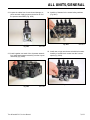 34
34
-
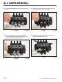 35
35
-
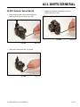 36
36
-
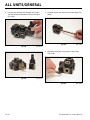 37
37
-
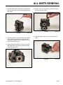 38
38
-
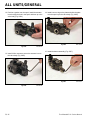 39
39
-
 40
40
-
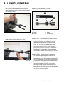 41
41
-
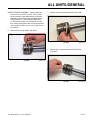 42
42
-
 43
43
-
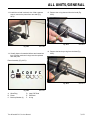 44
44
-
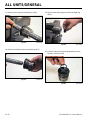 45
45
-
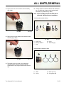 46
46
-
 47
47
-
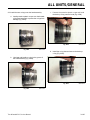 48
48
-
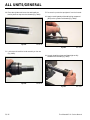 49
49
-
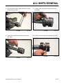 50
50
-
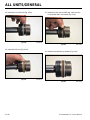 51
51
-
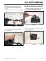 52
52
-
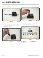 53
53
-
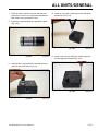 54
54
-
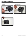 55
55
-
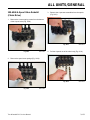 56
56
-
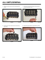 57
57
-
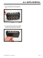 58
58
-
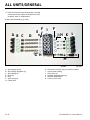 59
59
-
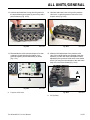 60
60
-
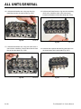 61
61
-
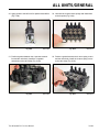 62
62
-
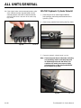 63
63
-
 64
64
-
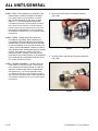 65
65
-
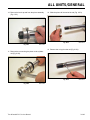 66
66
-
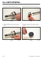 67
67
-
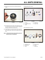 68
68
-
 69
69
-
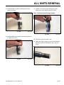 70
70
-
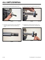 71
71
-
 72
72
-
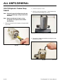 73
73
-
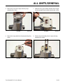 74
74
-
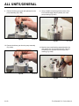 75
75
-
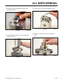 76
76
-
 77
77
-
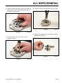 78
78
-
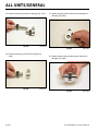 79
79
-
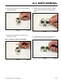 80
80
-
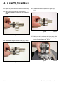 81
81
-
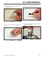 82
82
-
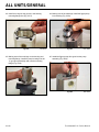 83
83
-
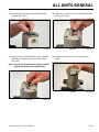 84
84
-
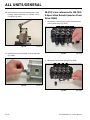 85
85
-
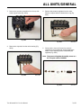 86
86
-
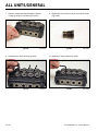 87
87
-
 88
88
-
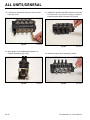 89
89
-
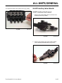 90
90
-
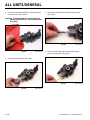 91
91
-
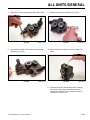 92
92
-
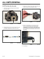 93
93
-
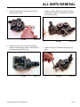 94
94
-
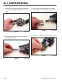 95
95
-
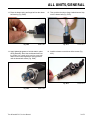 96
96
-
 97
97
-
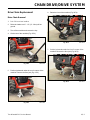 98
98
-
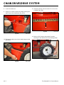 99
99
-
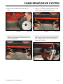 100
100
-
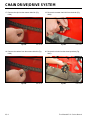 101
101
-
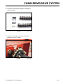 102
102
-
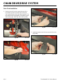 103
103
-
 104
104
-
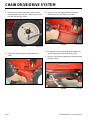 105
105
-
 106
106
-
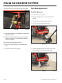 107
107
-
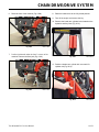 108
108
-
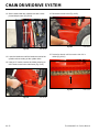 109
109
-
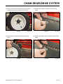 110
110
-
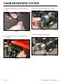 111
111
-
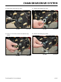 112
112
-
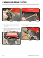 113
113
-
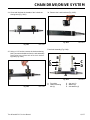 114
114
-
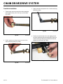 115
115
-
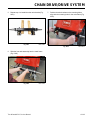 116
116
-
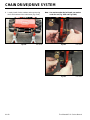 117
117
-
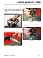 118
118
-
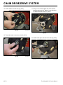 119
119
-
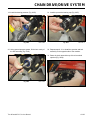 120
120
-
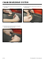 121
121
-
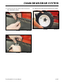 122
122
-
 123
123
-
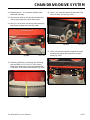 124
124
-
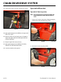 125
125
-
 126
126
-
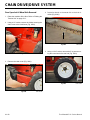 127
127
-
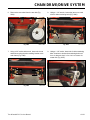 128
128
-
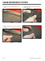 129
129
-
 130
130
-
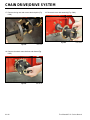 131
131
-
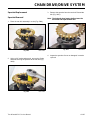 132
132
-
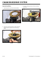 133
133
-
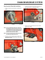 134
134
-
 135
135
-
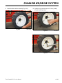 136
136
-
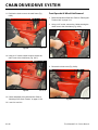 137
137
-
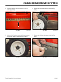 138
138
-
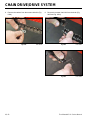 139
139
-
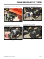 140
140
-
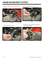 141
141
-
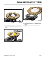 142
142
-
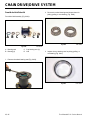 143
143
-
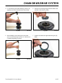 144
144
-
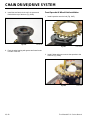 145
145
-
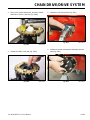 146
146
-
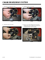 147
147
-
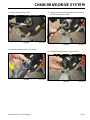 148
148
-
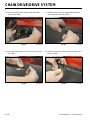 149
149
-
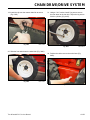 150
150
-
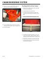 151
151
-
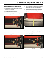 152
152
-
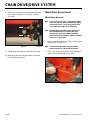 153
153
-
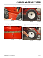 154
154
-
 155
155
-
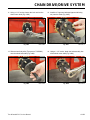 156
156
-
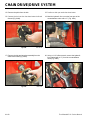 157
157
-
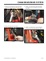 158
158
-
 159
159
-
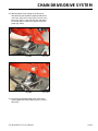 160
160
-
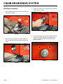 161
161
-
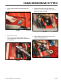 162
162
-
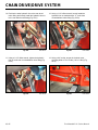 163
163
-
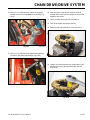 164
164
-
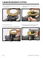 165
165
-
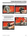 166
166
-
 167
167
-
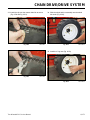 168
168
-
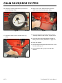 169
169
-
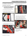 170
170
-
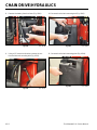 171
171
-
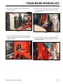 172
172
-
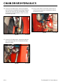 173
173
-
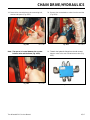 174
174
-
 175
175
-
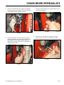 176
176
-
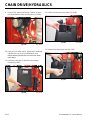 177
177
-
 178
178
-
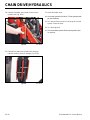 179
179
-
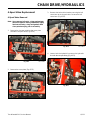 180
180
-
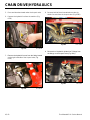 181
181
-
 182
182
-
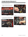 183
183
-
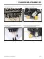 184
184
-
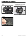 185
185
-
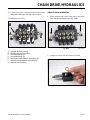 186
186
-
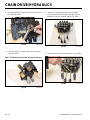 187
187
-
 188
188
-
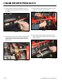 189
189
-
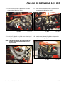 190
190
-
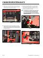 191
191
-
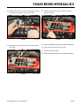 192
192
-
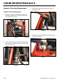 193
193
-
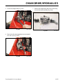 194
194
-
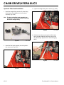 195
195
-
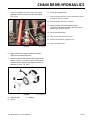 196
196
-
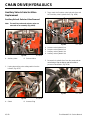 197
197
-
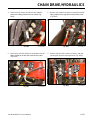 198
198
-
 199
199
-
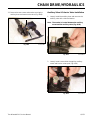 200
200
-
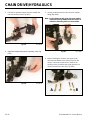 201
201
-
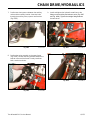 202
202
-
 203
203
-
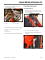 204
204
-
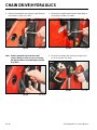 205
205
-
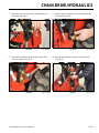 206
206
-
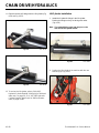 207
207
-
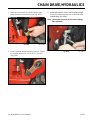 208
208
-
 209
209
-
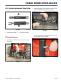 210
210
-
 211
211
-
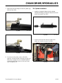 212
212
-
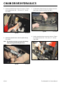 213
213
-
 214
214
-
 215
215
-
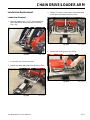 216
216
-
 217
217
-
 218
218
-
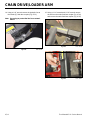 219
219
-
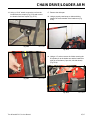 220
220
-
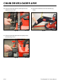 221
221
-
 222
222
-
 223
223
-
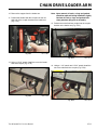 224
224
-
 225
225
-
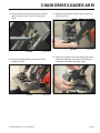 226
226
-
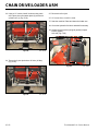 227
227
-
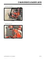 228
228
-
 229
229
-
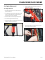 230
230
-
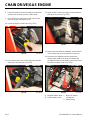 231
231
-
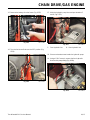 232
232
-
 233
233
-
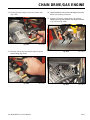 234
234
-
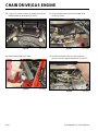 235
235
-
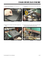 236
236
-
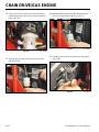 237
237
-
 238
238
-
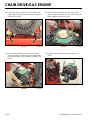 239
239
-
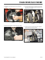 240
240
-
 241
241
-
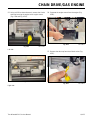 242
242
-
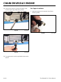 243
243
-
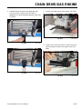 244
244
-
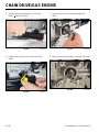 245
245
-
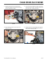 246
246
-
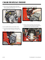 247
247
-
 248
248
-
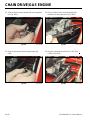 249
249
-
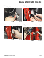 250
250
-
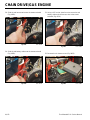 251
251
-
 252
252
-
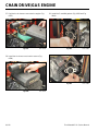 253
253
-
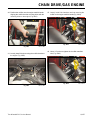 254
254
-
 255
255
-
 256
256
-
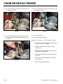 257
257
-
 258
258
-
 259
259
-
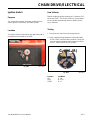 260
260
-
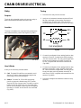 261
261
-
 262
262
-
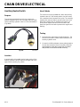 263
263
-
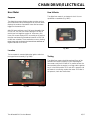 264
264
-
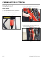 265
265
-
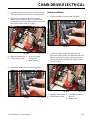 266
266
-
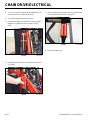 267
267
-
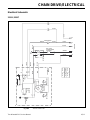 268
268
-
 269
269
-
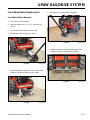 270
270
-
 271
271
-
 272
272
-
 273
273
-
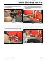 274
274
-
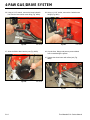 275
275
-
 276
276
-
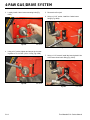 277
277
-
 278
278
-
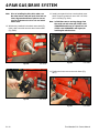 279
279
-
 280
280
-
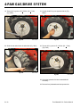 281
281
-
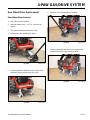 282
282
-
 283
283
-
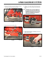 284
284
-
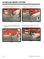 285
285
-
 286
286
-
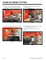 287
287
-
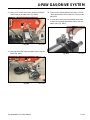 288
288
-
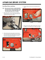 289
289
-
 290
290
-
 291
291
-
 292
292
-
 293
293
-
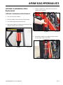 294
294
-
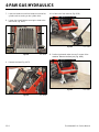 295
295
-
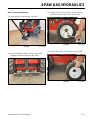 296
296
-
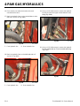 297
297
-
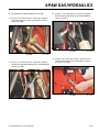 298
298
-
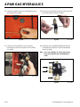 299
299
-
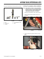 300
300
-
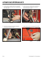 301
301
-
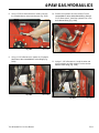 302
302
-
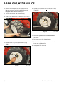 303
303
-
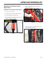 304
304
-
 305
305
-
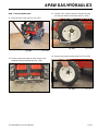 306
306
-
 307
307
-
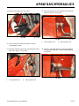 308
308
-
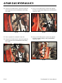 309
309
-
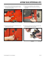 310
310
-
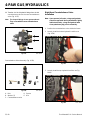 311
311
-
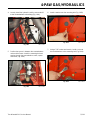 312
312
-
 313
313
-
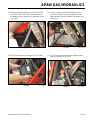 314
314
-
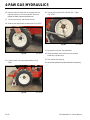 315
315
-
 316
316
-
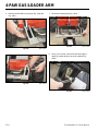 317
317
-
 318
318
-
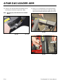 319
319
-
 320
320
-
 321
321
-
 322
322
-
 323
323
-
 324
324
-
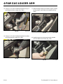 325
325
-
 326
326
-
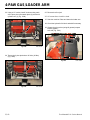 327
327
-
 328
328
-
 329
329
-
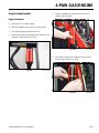 330
330
-
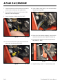 331
331
-
 332
332
-
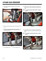 333
333
-
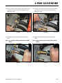 334
334
-
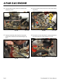 335
335
-
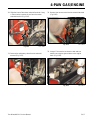 336
336
-
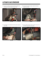 337
337
-
 338
338
-
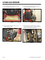 339
339
-
 340
340
-
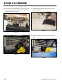 341
341
-
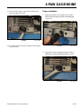 342
342
-
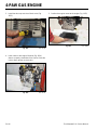 343
343
-
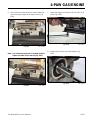 344
344
-
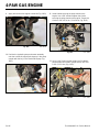 345
345
-
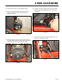 346
346
-
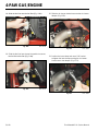 347
347
-
 348
348
-
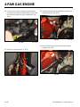 349
349
-
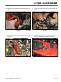 350
350
-
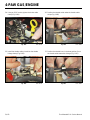 351
351
-
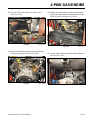 352
352
-
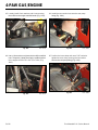 353
353
-
 354
354
-
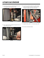 355
355
-
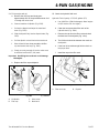 356
356
-
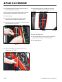 357
357
-
 358
358
-
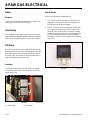 359
359
-
 360
360
-
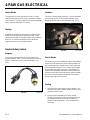 361
361
-
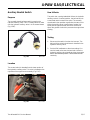 362
362
-
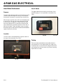 363
363
-
 364
364
-
 365
365
-
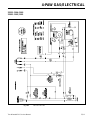 366
366
-
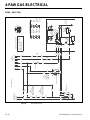 367
367
-
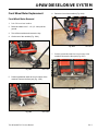 368
368
-
 369
369
-
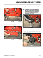 370
370
-
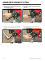 371
371
-
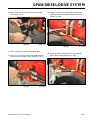 372
372
-
 373
373
-
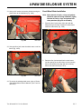 374
374
-
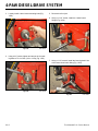 375
375
-
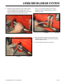 376
376
-
 377
377
-
 378
378
-
 379
379
-
 380
380
-
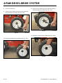 381
381
-
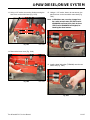 382
382
-
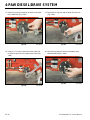 383
383
-
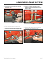 384
384
-
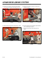 385
385
-
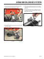 386
386
-
 387
387
-
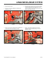 388
388
-
 389
389
-
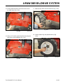 390
390
-
 391
391
-
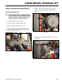 392
392
-
 393
393
-
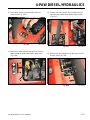 394
394
-
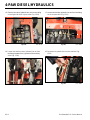 395
395
-
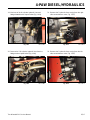 396
396
-
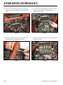 397
397
-
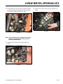 398
398
-
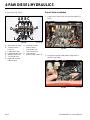 399
399
-
 400
400
-
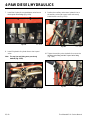 401
401
-
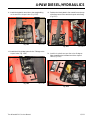 402
402
-
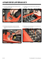 403
403
-
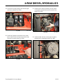 404
404
-
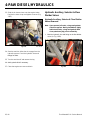 405
405
-
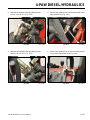 406
406
-
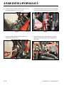 407
407
-
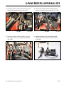 408
408
-
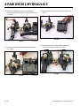 409
409
-
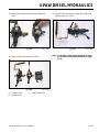 410
410
-
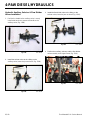 411
411
-
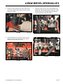 412
412
-
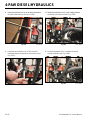 413
413
-
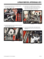 414
414
-
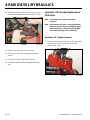 415
415
-
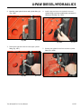 416
416
-
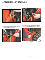 417
417
-
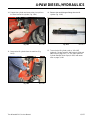 418
418
-
 419
419
-
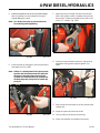 420
420
-
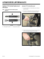 421
421
-
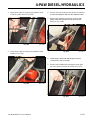 422
422
-
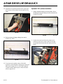 423
423
-
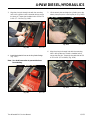 424
424
-
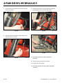 425
425
-
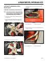 426
426
-
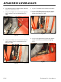 427
427
-
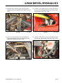 428
428
-
 429
429
-
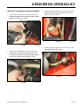 430
430
-
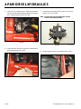 431
431
-
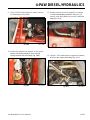 432
432
-
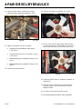 433
433
-
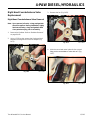 434
434
-
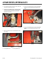 435
435
-
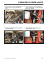 436
436
-
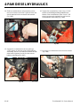 437
437
-
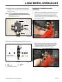 438
438
-
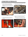 439
439
-
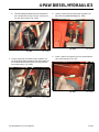 440
440
-
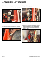 441
441
-
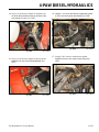 442
442
-
 443
443
-
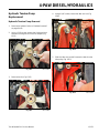 444
444
-
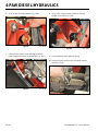 445
445
-
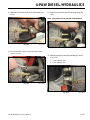 446
446
-
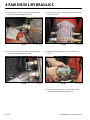 447
447
-
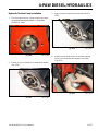 448
448
-
 449
449
-
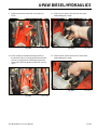 450
450
-
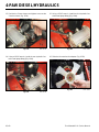 451
451
-
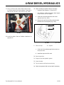 452
452
-
 453
453
-
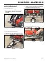 454
454
-
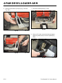 455
455
-
 456
456
-
 457
457
-
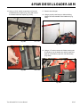 458
458
-
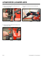 459
459
-
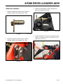 460
460
-
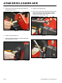 461
461
-
 462
462
-
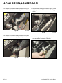 463
463
-
 464
464
-
 465
465
-
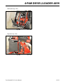 466
466
-
 467
467
-
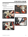 468
468
-
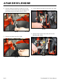 469
469
-
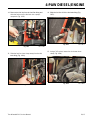 470
470
-
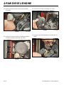 471
471
-
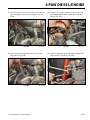 472
472
-
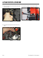 473
473
-
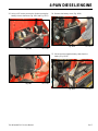 474
474
-
 475
475
-
 476
476
-
 477
477
-
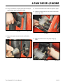 478
478
-
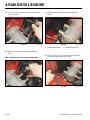 479
479
-
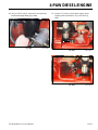 480
480
-
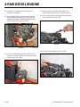 481
481
-
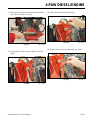 482
482
-
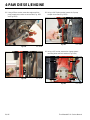 483
483
-
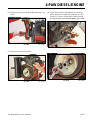 484
484
-
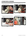 485
485
-
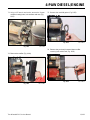 486
486
-
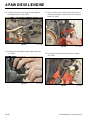 487
487
-
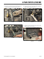 488
488
-
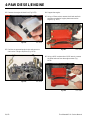 489
489
-
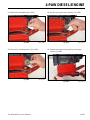 490
490
-
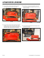 491
491
-
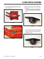 492
492
-
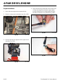 493
493
-
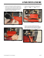 494
494
-
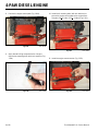 495
495
-
 496
496
-
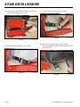 497
497
-
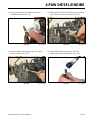 498
498
-
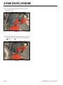 499
499
-
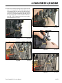 500
500
-
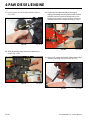 501
501
-
 502
502
-
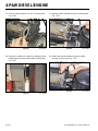 503
503
-
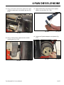 504
504
-
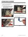 505
505
-
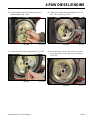 506
506
-
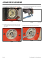 507
507
-
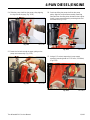 508
508
-
 509
509
-
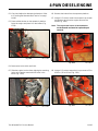 510
510
-
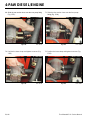 511
511
-
 512
512
-
 513
513
-
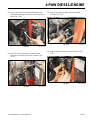 514
514
-
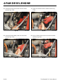 515
515
-
 516
516
-
 517
517
-
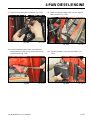 518
518
-
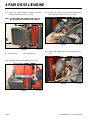 519
519
-
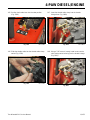 520
520
-
 521
521
-
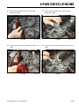 522
522
-
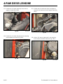 523
523
-
 524
524
-
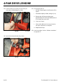 525
525
-
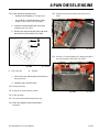 526
526
-
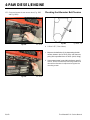 527
527
-
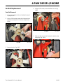 528
528
-
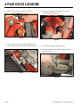 529
529
-
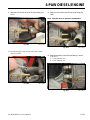 530
530
-
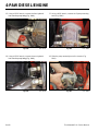 531
531
-
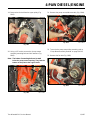 532
532
-
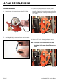 533
533
-
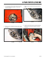 534
534
-
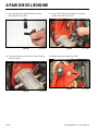 535
535
-
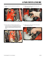 536
536
-
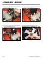 537
537
-
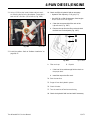 538
538
-
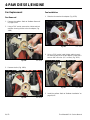 539
539
-
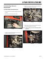 540
540
-
 541
541
-
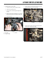 542
542
-
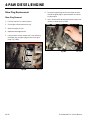 543
543
-
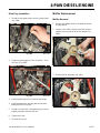 544
544
-
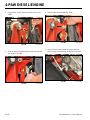 545
545
-
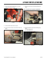 546
546
-
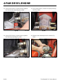 547
547
-
 548
548
-
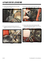 549
549
-
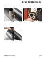 550
550
-
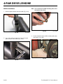 551
551
-
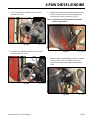 552
552
-
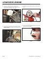 553
553
-
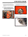 554
554
-
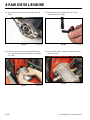 555
555
-
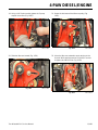 556
556
-
 557
557
-
 558
558
-
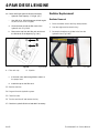 559
559
-
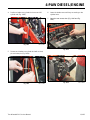 560
560
-
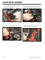 561
561
-
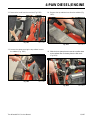 562
562
-
 563
563
-
 564
564
-
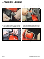 565
565
-
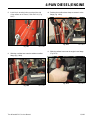 566
566
-
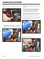 567
567
-
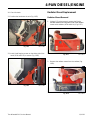 568
568
-
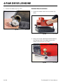 569
569
-
 570
570
-
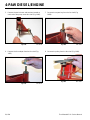 571
571
-
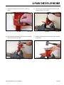 572
572
-
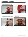 573
573
-
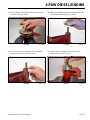 574
574
-
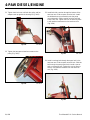 575
575
-
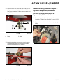 576
576
-
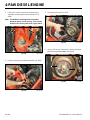 577
577
-
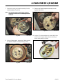 578
578
-
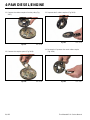 579
579
-
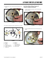 580
580
-
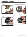 581
581
-
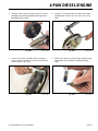 582
582
-
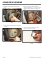 583
583
-
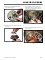 584
584
-
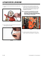 585
585
-
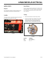 586
586
-
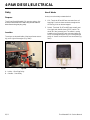 587
587
-
 588
588
-
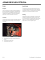 589
589
-
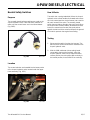 590
590
-
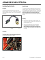 591
591
-
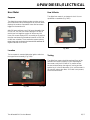 592
592
-
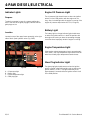 593
593
-
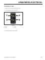 594
594
-
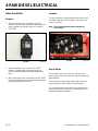 595
595
-
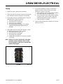 596
596
-
 597
597
-
 598
598
-
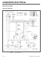 599
599
-
 600
600
-
 601
601
-
 602
602


Toro Dingo 222 Compact Utility Loader User manual
- Category
- Engine
- Type
- User manual
Ask a question and I''ll find the answer in the document
Finding information in a document is now easier with AI
Related papers
-
Toro Headlight Kit, Two-Stage Snowthrowers Installation guide
-
-
-
-
-
-
-
-
-
Other documents
-
SPT 40028 Operating instructions
-
KMC KMC080 Operating instructions
-
-
-
-
-
Blichmann TT-PUMP-BKT User manual
-
Robin Semi-Matic Head Operating instructions
-
Legrand Qfree Installation guide
-
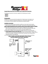 Rugged Ridge 15201.04 Installation guide
