Page is loading ...

22-73-0004 Rev. A
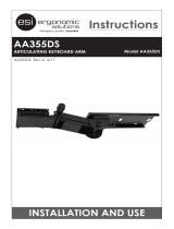
CABLE MANAGEMENT
After the technology has been installed, ensure there is enough slack in the cables from peripherals.
STEP 1
Slide the cable management tray forward to disengage
the tray from the bottom of the arm.
STEP 2
Lay all cables (e.g. power, and/or
USB cable, see Device Installation section)
into the cable management tray.
STEP 3
Re-attach the cable tray in the reverse order in Step 1 (note orientation).
If desired, tighten the four screws to lock the tray to the arm.
Do not over tighten.
STEP 4
Route cables under the track cover.
Manufactured for Midmark Corporation
690 Knox Street, Suite 100
Torrance, CA 90502
(800) 624-8950
midmark.com
For questions regarding installation,
please call 1-800-643-6275
Unlocked
STEP 2
STEP 2
STEP 4
Locked
STEP 1
Locked
Unlocked
STEP 3
133014180 Rev. A
22-73-0004 Rev. A
133014180 Rev. A
IQvitals
®
Zone
TM
Wall Mount Articulating Arm
Weight Capacity
5-15 lbs.
P/N 2-200-0082

2
IQvitals
®
Zone™ Wall Mount Articulating Arm
Tools Required / Installation Warnings / Disclaimer / Safety Warning / Adjustment Notifi cation ..............................3
Mounting Height ............................................................................................................................................. 4
How to Install Togglers .................................................................................................................................... 5
Mounting Surface ....................................................................................................................................6 - 7
Pivot Limiter ...................................................................................................................................................8
Optional Extension Arm ...................................................................................................................................9
Main Arm Installation
Installation direct to Wall Ear
Installation to the Extension Arm ..........................................................................................................
9
Counterbalance the Arm ............................................................................................................................. 10
Tray Leveling Adjustments ........................................................................................................................... 11
Cable Management ..................................................................................................................................... 12
TABLE OF CONTENTS
11
IQvitals
®
Zone™ Wall Mount Articulating Arm
LEVELING ADJUSTMENTS (Left to Right)
Adjustment is to be made after all technology has been installed.
STEP 1
Remove the trim cap at the back of the arm.
STEP 2
Use the 3/16” Allen Key to turn the top bolt at the back of the arm.
Turn the bolt until the tray is level.
STEP 3
Confi rm that surface is level with spirit level.
STEP 4
Replace the trim cap at the back of the arm.
ATTENTION:
Arm must be parallel to the work surface and
swiveled 90° to the base when adjusting.
+ –
LEVEL
ADJUST
STEP 2
STEP 3
3/16”
Do not overtighten
bolts as this may cause
damage to the product.
o
n
ot
o
ve
rt
ight
e
!

10
IQvitals
®
Zone™ Wall Mount Articulating Arm
COUNTERBALANCE THE ARM
Once all after-sale technology is installed, perform the following adjustments to ensure the arm
raises and lowers as required and does not freely drift up or down.
ATTENTION:
Arm must be held in the downward
position while to making adjustments.
1/4”
Do not overtighten
bolts as this may cause
damage to the product.
o not overtight
e
!
STEP 1
Remove the trim cap at the back of the arm.
STEP 2
Use the 1/4” Allen Key to turn the middle bolt at the back
of the arm. Turning the bolt clockwise decreases the
spring force reducing the counter balance load.
Turning the bolt counterclockwise increases
The spring force increasing the counter
balance load.
STEP 3
Adjust the middle bolt until the arm counter
balance is acceptable.
STEP 4
Replace the trim cap at the back of the arm.
STEP 2 & 3
STEP 1 & 4
+–
COUNTER-
BALANCE
ADJUST
3
IQvitals
®
Zone™ Wall Mount Articulating Arm
INSTALLATION WARNINGS:
•
Read the entire instruction manual before beginning any installation or assembly.
•
The installer must verify that the entire wall safely supports the combined weight of all the attached equipment and hardware.
•
Improper installation of this product may cause extensive property damage or serious personal injury, either during or after installation.
DISCLAIMER:
•
The manufacturer and/or distributor will bear no responsibility for any damages of any kind arising from any improper installation.
•
In no way will the manufacturer or distributor be held liable for any damage to the monitor, property or personal injury should an
outside force either intentionally or unintentional be applied to the monitor or monitor mounting bracket causing it to pull off the wall.
SAFETY WARNING:
•
California installations may require specifi c anchorage and additional supports. Check with local authorities for codes in your area.
Other seismic states will have similar regulations.
•
Prior to drilling, verify the location of any electrical wiring with in the wall. An electrical short can kill or create serious injury and fi re
hazard both during and after installation.
•
OSHPD certifi cate available upon request.
ADJUSTMENT NOTIFICATION:
•
Routine maintenance checks and adjustments are suggested to properly support the quality and optimal performance of this product.
Refer to adjustment suggestions on last page of booklet, or contact your distributor for further detailed information.
•
Over tightening of bolts during installation or adjustments may damage the product and affect the function and warranty.
Allen Wrenches: 1/4”, 7/32”, 3/16” and 1/8”
Socket Wrench: 7/16”
Drill Bit: 1/8” and 1/2”
Phillips Screwdriver
TOOLS REQUIRED
Optional:
Mitre Saw

4
IQvitals
®
Zone™ Wall Mount Articulating Arm
MOUNTING HEIGHT
If installing directly to drywall
(hollow wall applications) please
note the bottom of the wall ear
must be positioned between
8”-14” from the bottom of
the track.
14”
1/4”
Allen
wrench
8”
• Loosen, but do not
remove 4 corner bolts
• Place in desired position
• Level the wall ear
• Tighten bolts to 200 in-lbs
force to ensure the unit
is securely fastened
POSITIONING WALL EAR
Improper installation of this
product may cause extensive
property damage or serious
personal injury, either during
or after installation.
!
We recommend having the wall ear
installed at the following heights.
21.75” FROM FLOOR TO
BOTTOM OF WALL EAR
21.75”
8.00” TO 14.00”
NOTE: Unit needs to be mounted
less then 3’ away from a
power outlet so power
cords can reach.
9
IQvitals
®
Zone™ Wall Mount Articulating Arm
MAIN ARM INSTALLATION
MAIN ARM INSTALLATION DIRECT TO WALL EAR
7/32”
+ –
TENSION
ADJUST
Do not overtighten
bolts as this may cause
damage to the product.
b
d
!

8
IQvitals
®
Zone™ Wall Mount Articulating Arm
180°
PIVOT LIMITER
Position pins as shown to
limit rotation to the right
Limits 90° right rotation Allows 180° rotation
Limits 90° left rotation Limits total rotation
Position pin at 12:00 to prevent
the arm from coming in direct
contact with the wall on either side
Position pins as shown
to limit rotation to the left
Position pins at 3:00 & 9:00
for a full rotation lock out
This item is to be positioned (if required) before installing the extension arm or main arm to the wall ear.
LIMITER HOLES ON THE EXTENSION ARM LIMITER HOLES ON THE MAIN ARM
PIVOT LIMITER VIEW FROM UNDERSIDE
90°
90°
Pin
Pin
Pin
Pin
Pin
Pin
Pin
Lightly tap the pin to
ensure it stays in place
during installation.
5
IQvitals
®
Zone™ Wall Mount Articulating Arm
HOW TO INSTALL TOGGLERS
Use a level and ensure track is fl ush, fl at and snug to the wall.
Mark hole locations prior to drilling and install toggler bolts in
appropriate locations.
Use bolts provided to secure track to the wall. Refer to the reference guide on pages 6 and 7.
OR

6
IQvitals
®
Zone™ Wall Mount Articulating Arm
MOUNTING SURFACE
M6 Togglers
M6 x 75mm
Wall Track
Drywall or Similar
M6 Togglers
NOTE: Bolts are to be placed in the horizontal center of the 2”x 4”
Steel Stud.
Minimum 2” x 4” 24ga.
Steel Stud
2” Nominal
4” Nominal
Wall Track
Minimum 2” x 4” 24ga.
Steel Stud
M6 x 75mm
M6 Togglers
Drywall or Similar
M6 Togglers
M6 x 75mm
34” TRACK - 10 outer holes 34” TRACK - 5 inner holes
DIRECT TO DRYWALL STEEL STUD
TOGGL ER®
TOGGLER®
Toggler
required
Toggler
required
M6 x 75mm
M6 Togglers
M6 x 75mm
Mortar Bed
34” TRACK
- 5 inner holes
NOTE: Bolts must pass through concret
through mortar bed between blocks no
r
When attaching to concrete blocks, onl
y
Wall Track
CONCRETE WALL (block)
Concrete Blocks
CRITICAL: The wall ear must be positioned between 8”-14” from the
bottom of the track.
7
IQvitals
®
Zone™ Wall Mount Articulating Arm
NOTE: Screws are to be placed in the horizontal center and must
penetrate at least 2” into the wood stud.
4” Nominal
2” Nominal
Minimum 2” x 4”
Wood Stud
1/4” x 2.50”
Wood Screw
Drywall or Similar
Wall Track
1/4” x 2.50” Wood Screw
Minimum 2” x 4”
Wood Stud
3/16” x 2-1/4” lg. Min. Tapcon
®
Concrete screws (not provided) to pass
through the wall track as per screw manufacturers intructions.
NOTE: Pre drilled holes to be created using Tapcon
®
drill bit for
3/16”x2-1/4”lg. concrete screws to a Min. hole depth of 2-1/2”
into concrete slab.
1-3/4” Min. Screw Embedment
2 1/2” Min.
Hole Depth
3/16” Concrete Screw
Concrete Slab
Wall Track
Drywall or Similar
3/16” Concrete
Screw
Concrete Slab
34” TRACK - 5 inner holes 34” TRACK - 5 inner holes
Concrete hardware not provided
WOOD STUD CONCRETE WALL (solid)
Toggler
NOT
required
Toggler
NOT
required
e block. Bolts must not pass
r
through the web within the blocks.
y
one bolt per cell allowed.
TOGGLER®
Toggler
required
Concrete Block
Mortar Bed
Drywall or Similar
M6 Togglers
M6 x 75mm
2 Min.
Penetration
/