B&G H5000 Pilot Installation guide
- Category
- Processors
- Type
- Installation guide

ENGLISH
H5000
Installation Manual
www.bandg.com

| 1
Preface | H5000 Installation
Preface
As Navico is continuously improving this product, we retain the
right to make changes to the product at any time which may not be
re ected in this version of the manual. Please contact your nearest
distributor if you require any further assistance.
It is the owner’s sole responsibility to install and use the instrument
and transducers in a manner that will not cause accidents, personal
injury or property damage. The user of this product is solely
responsible for observing safe boating practices.
NAVICO HOLDING AS AND ITS SUBSIDIARIES, BRANCHES AND
AFFILIATES DISCLAIM ALL LIABILITY FOR ANY USE OF THIS PRODUCT
IN A WAY THAT MAY CAUSE ACCIDENTS, DAMAGE OR THAT MAY
VIOLATE THE LAW.
Governing Language: This statement, any instruction manuals,
user guides and other information relating to the product
(Documentation) may be translated to, or has been translated from,
another language (Translation). In the event of any con ict between
any Translation of the Documentation, the English language
version of the Documentation will be the o cial version of the
Documentation.
This manual represents the product as at the time of printing. Navico
Holding AS and its subsidiaries, branches and a liates reserve the
right to make changes to speci cations without notice.
Copyright
Copyright © 2014 Navico Holding AS.
Warranty
The warranty card is supplied as a separate document.
In case of any queries, refer to the brand web site of your display or
system:
www.bandg.com
Note: Used to draw the reader’s attention to a comment or some
important information.
!Warning : Used when it is necessary to warn personnel that they
should proceed carefully to prevent risk of injury and/or damage to
equipment/personnel.

2 | Preface | H5000 Installation
Declarations and conformance
This equipment is intended for use in international waters as coastal
sea area administered by countries of the E.U. and E.E.A.
The H5000 system complies with the following regulations:
• CE under EMC directive 2004/108/EC
• Level 2 devices of the Radio communications (Electromagnetic
Compatibility) standard 2008
• The relevant Declaration of conformity is available in the H5000
section on the following website: www.bandg.com
H5000 displays meet the technical standards in accordance with Part
15.103 of the FCC rules.
About this manual
This manual is a reference guide for installing and commissioning
the H5000 Instrument and autopilot system. The manual assumes
that the installer has at very least, basic knowledge of DC electrical
systems, and of working with power tools with materials such as
berglass and wood.
An understanding of basic navigation, nautical terminology and
practices may be helpful in correct con guration of the product.
!Warning : It is your sole responsibility to install and use the
instrument and transducer(s) in a manner that will not cause
accidents, personal injury or property damage. Always observe safe
boating practices.
Note: The choice, location, and installation of transducers and other
components of the system are critical to the performance of the
system as intended. If in doubt, consult your dealer.
Note: Global Positioning System: The Global Positioning System
(GPS) is operated by the US Government which is solely responsible
for its operation, accuracy and maintenance. The GPS is subject to
changes which could a ect the accuracy and performance of all GPS
equipment anywhere in the world, including this system.

| 3
Liability & Safety Warning | H5000 Installation
Liability and safety warning
Navico accept no responsibility for the use and/or operation of this
equipment. It is the user’s responsibility to ensure that under all
circumstances the equipment is used for the purposes for which it
has been designed.
Warning: Calibration
The safe operation of this equipment is dependent on accurate and
correct calibration. Incorrect calibration of this equipment may lead
to false and inaccurate navigational readings placing the yacht into
danger.
Warning: Operational Hazard
The H5000 system is an electronic navigation aid and is designed
to assist in the navigation of your yacht. It is not designed to totally
replace conventional navigation procedures and precautions. All
necessary precautions should be taken to ensure that the yacht is not
placed into danger.
The Pilot is an aid to steering the vessel. It is the user’s responsibility
to ensure safe control and movement of the vessel at all times.
Caution: Electrical Supply
This equipment is designed for use with a power supply source of
12 V DC. The application of any other power supply may result in
permanent damage to the equipment.
Caution: Cleaning
The use of alcohol or solvent-based cleaners will damage this
equipment and any warranty in force will be invalidated.
Caution: Processor Installation
All B&G Processors should be installed below decks in a dry location
protected from water and moisture.
Power O Disclaimer
When in standby mode the H5000 system continues to consume
power. To conserve the vessel’s battery life switch o power at the
main breaker.

| 5
Contents | H5000 Installation
Contents
7 Introduction
7 About B&G
7 About this manual
8 System introduction
9 H5000 system example
10 H5000 performance system example
11 H5000 typical autopilot system
12 Planning
12 Mounting locations
14 System architecture
14 NMEA 2000® device connection
15 Wiring guidelines
16 Network layout
17 Bridged network
18 Network power supply
19 H5000 Central Processor Unit - CPU
20 Status LEDs
21 CPU Installation
25 H5000 Central Processor wiring
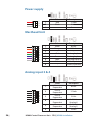
26 Power supply
26 Masthead Unit
26 Analog input 3 & 4
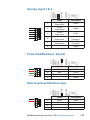
27 Analog input 1 & 2
27 Pulse (Paddlewheel - Speed)
27 Man Overboard Button input
28 Digital output (Alarm)
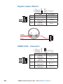
28 NMEA 0183 - Channel 2
29 NMEA 0183 - Channel 1
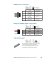
29 Network (NMEA 2000 compatible)
29 USB update port
30 Reset button
30 Ethernet port
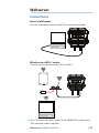
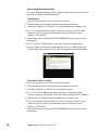
31 Webserver
31 Connections
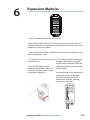
33 Expansion Modules
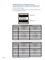
34 H5000 Expansion Module wiring
35 H5000 Expansion Module wiring example
36 Module Jumpers

6 | Contents | H5000 Installation
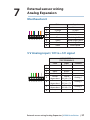
37 External sensor wiring
Analog Expansion
37 Masthead unit
37 5 V Analog input / 0 V to +5 V signal
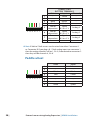
38 Paddle wheel
39 Paddle wheel & Sea temperature
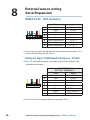
40 External sensor wiring
Serial Expansion
40 NMEA 0183 - GPS Antenna
40 Halcyon Gyro Stabilized Compass - HGSC
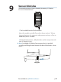
41 Sensor Modules
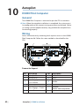
42 Autopilot
42 H5000 Pilot Computer
42 General
42 Wiring
43 Power
43 Drive
44 Engage (Clutch)
44 Alarm
45 NMEA 0183
45 Rudder
45 Remote
46 Simnet (Network)
46 Turning on for the rst time
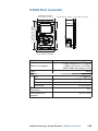
47 H5000 Pilot Controller
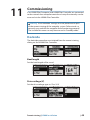
49 Commissioning
49 Dockside
57 Maintenance
57 General maintenance
58 Software upgrade
58 H5000 CPU
59 H5000 Pilot Computer / Pilot Controller
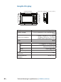
59 Graphic Display
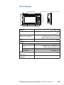
60 Race display
60 Analog / Serial expansion module
60 Navico NMEA 2000 devices
61 Technical drawings &
speci cations
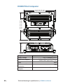
61 H5000 Central Processor Unit - CPU
62 Graphic Display
63 Race display
64 H5000 Pilot Computer
65 H5000 Pilot Controller

| 7
Introduction | H5000 Installation
Introduction
About B&G
B&G has welcomed the constant challenge to develop new electronic
solutions for every sailor’s need. Harnessing technical developments
and providing proven solutions has continued to be the focus that
keeps B&G on the leading edge of advanced marine electronics.
Proven in the world’s most testing environments, B&G o ers the most
accurate and reliable systems used by blue water cruisers, single-
handed racers and record breakers alike, rmly establishing ourselves
as one of the leading innovators of the most highly advanced marine
electronics. B&G is renowned for tried and trusted solutions and is
ever evolving to o er the best technology to the customer.
About this manual
Instructions in this handbook describe the installation and routine
maintenance of the H5000 system.
1

8 | System introduction | H5000 Installation
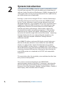
System introduction
The innovative B&G H5000 instrument system is powered by a smart
Central Processing Unit (CPU) with the ability to run three levels of
software, Hydra, Hercules and Performance. H5000 is designed for all
sailing types from cruising to racing and provides the sophistication
you need without over-complication.
Running a system with an integral CPU has a wealth of advantages
including web-browser based setup via the new H5000 interface,
for easy set-up, calibration, commissioning, backup/restore and
advanced diagnostics. It also expands the system’s communications
capabilities, with dual NMEA 0183 ports with selectable message
con guration, Ethernet link to the webserver and the ability to
interface with other software apps. Add a wireless router and
you bene t from tablet/smartphone integration. A CPU provides
enhanced sensor support and speci c sailing features like wind
correction for heel/trim angle and true wind correction – improving
the data displayed to the user and guiding the autopilot. It also
simpli es seemingly complex calibrations through AutoCal
calibration routines.
The H5000 CPU delivers enhanced HV display control, letting you
alternate the displays between two variables, for more e cient
display use, and provides support for both expansion modules
and many of B&G’s existing sensors. In addition, the CPU provides
advanced MOB function with dedicated MOB button input and dead
reckoning of relative MOB position, allowing for tide, based on the
initial MOB position or as updated via AIS SART with compatible
equipment.
This manual describes the standard system and then describes how
the system can be expanded.
The system is connected together by the NMEA 2000®
communication network using Micro-C connectors, which handles
all of the data that travels between devices including the Central
Processor Unit, Pilot Computer, Modules, Analog Displays, Graphic &
Race Displays, Pilot Controller and HV Displays.
2

| 9
System introduction | H5000 Installation
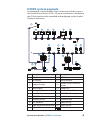
H5000 system example
An example of a typical H5000 system. At the centre of the system is
the Central Processor Unit (CPU). All sensor information is fed back to
the CPU and can be easily controlled and con gured via the Graphic
Display or webserver.
12V
12V
12V
12V
2 3 4 5 6 7
8912
10 11
1
18
17
T
T
13
19
16
15
14
12V
PILOT
20
WIFI-1
No. Description No. Description
1213 Masthead unit 11 3D Motion sensor
2HV Display 12 Alarm module
3Graphic Display 13 Wireless Access Point or
Router
4Race display 14 H5000 CPU
5Analog display 15 Man Overboard Button
6Zeus Touch 16 H5000 Pilot Computer
7H5000 Pilot Controller 17 Rudder Feedback Unit
8Heading sensor 18 Hydraulic Ram
9GPS antenna 19 Speed sensor
10 High-Resolution Barometer 20 Depth sensor
TMicro-C Terminator 12V 12 Volt DC power

10 | System introduction | H5000 Installation
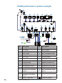
H5000 performance system example
12V
12V
2 3 4 5 6
13
16 17
14 15
1
25
24
T
T
27
28 29
19 20 20
18 23
21
22
78
11
1210
9
9
12V
12V
12V
26
ECHORADARCHART NAV INFO PAGES
MENU
PLOT
GO TO
MARK
VESSEL
WIN
IN
MOB ABC DEF
123
JKLGHI MNO
456
TUV
PQRS
WXYZ
7
STBY
AUTO
PWR
8
0
9
OUT
No. Description No. Description
1Fwd & Aft vertical MHU 16 Motion sensor
2HV Display 17 Alarm module
3Graphic Display 18 H5000 CPU
4Race Display 19 Man Overboard Button
5Analogue display 20 Analog module
6Zeus Touch 21 Analog module
7Zeus 22 Analog sensor
8H5000 Pilot Controller 23 H5000 Pilot Computer
9Analog module 24 Rudder Feedback Unit
10 Analog module 25 Hydraulic ram
11 Mast rotation sensor 26 Deckman via serial port
12 Serial Expansion Module 27 NMEA 0183 Tx / Rx
13 Halcyon Gyro Stabilized
Compass 28 Port & Starboard speed
sensor
14 GPS 29 Depth sensor
15 Barometric & Air temp
sensor
TMicro-C Terminator 12V 12 Volt DC power

| 11
System introduction | H5000 Installation
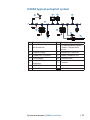
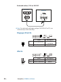
H5000 typical autopilot system
12V
1
T T
2
5
7
68
11
4
3
12V
10
9
D
PT
12V
No. Description No. Description
1Masthead unit 7
DST800 combined Speed
/ Depth / Temperature
sensor
2Graphic Display 8H5000 Pilot Computer
3H5000 Pilot Controller 9Rudder Feedback Unit
4GPS antenna 10 Hydraulic Ram
5Micro-C CAN bus
backbone 11 Compass
6H5000 CPU
TMicro-C Terminator 12V 12 Volt DC power

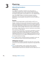
12 | Planning | H5000 Installation
Planning
Mounting locations
H5000 CPU
The H5000 CPU should be installed in a dry place with easy
accessibility. The enclosure is water resistant to IP65 but will not
survive prolonged immersion. The engine box is NOT a good place
to install your instrument system processors; it is hot and electrically
noisy. The H5000 CPU does not contain orientation sensitive
components so it is NOT necessary to mount the unit vertically,
however it is recommended to orientate the unit with all cable exits
downwards.
Displays
Choose the mounting locations carefully before you drill or cut.
Displays should be mounted so that the operator can easily use the
controls and clearly see the display screen. Ensure that the suncover
can be easily tted and removed. Be sure to leave a direct path for all
of the cables. B&G displays are high-contrast and anti-re ective, and
are viewable in direct sunlight, but for best results install the display
out of direct sunlight. The chosen location should have minimal glare
from windows or bright objects.
The enclosure that the display is mounted in should be dry and well
ventilated. The ventilation of the space behind the unit should be
enough to prevent excessive heat build up as a combined result of
radiated heat o the heat sink, and sunlight heating of the enclosure.
In very small enclosures, also subject to heating from the sun, it may
be required to t forced cooling.
Note: Graphic Displays should be located or mounted in such a way
as to retain access to the service port on the rear of the unit.
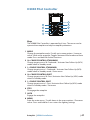
H5000 Pilot Controller
The H5000 Pilot Controllers should be mounted with special regard
to the units’ environmental protection, temperature range and cable
length.
Note: If installed outdoors, select a position and a mounting
option that prevents water from remaining on the display. It is
recommended to cover the units with their suncover when not in use.
3

| 13
Planning | H5000 Installation
General
Ensure that any holes cut are in a safe position and will not weaken
the boat’s structure. If in doubt, consult a quali ed boat builder.
Before cutting a hole in a panel, make sure that there are no hidden
electrical wires or other parts behind the panel.
Do not mount any part where it can be used as a hand hold, where
it might be submerged, or where it will interfere with the operation,
launching or retrieving of the boat.
Leave su cient clearance space to connect all relevant cables.
For overall width and height requirements, please see the
dimensions section and mounting template of each device.

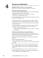
14 | System architecture | H5000 Installation
System architecture
NMEA 2000® device connection
All devices connect to the network via a Micro-C connector.
Essential network information
• The network consists of a linear “backbone” from which “drop cables”
connect to H5000 and NMEA 2000 devices
• H5000 products use Micro-C style connectors, this allows
compatibility with NMEA 2000 networks.
Note: Some B&G products use Simnet proprietary connectors, but are
compatible via adaptor cables.
• A single drop cable has a maximum length of 6 m (20 ft). The total
length of all drop cables combined should not exceed 78 m (256 ft)
• The network has a maximum cable length of 100 m (328 ft), between
any two terminators
• The network needs to have a Micro-C Terminator at each end of the
backbone. A Micro-C Terminator can be one of the following:
• A Micro-C Terminator blank plug
• A 508 model wind transducer (where the mast cable is one end of
the backbone)
Planning and installing a network backbone
The network backbone needs to run between the locations of all
products you want to install, typically in a bow to stern layout, and be
no further than 6 m from a device to be connected.
Choose from the following components to make up your network
backbone:
• Micro-C interconnecting cables
• Micro-C power cables - with or without termination
• T-connectors. Use at locations where you want to connect a device by
drop cable
Note: If using a 508 wind sensor connected directly to the network,
the mast cable should be connected as the nal length of cable at
one end of the backbone, as the sensor is tted with a termination
resistor.
Note Most NMEA 2000 devices can be connected directly to the
network backbone. Simnet devices can be connected to the Micro-C
CAN bus backbone by using adapter cables.
4

| 15
System architecture | H5000 Installation
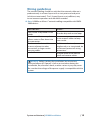
Wiring guidelines
The network cabling should be such that the network cable run is
predominantly in a linear layout with a start point and end point
(which are terminated). “Star” shaped layouts are ine cient, may
cause incorrect operation and should be avoided.
Note: H5000 uses Micro-C network cabling compatible with NMEA
2000 devices.
Don’t do this... Do this...
Don’t make sharp bends in the
cables Do make drip and service loops
Don’t run cables in a way that
allows water to ow down into
the connectors
Do tie-wrap all cables to keep
them secure
Don’t route the data cables
in areas adjacent to radar,
transmitter, or large current
carrying cables
If cables are shortened,
lengthened, or re-terminated, do
insulate and protect all wiring
connections
Do leave room at the back to
install and remove cables
!Warning : Before starting the installation, be sure to turn
electrical power o . If power is left on or turned on during the
installation, re, electrical shock, or other serious injury may occur.
Be sure that the voltage of the power supply is compatible with the
system.

16 | System architecture | H5000 Installation
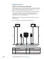
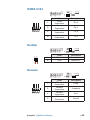
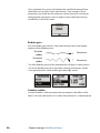
Network layout
Guideline maximum drop cable length
For best performance it is recommended that drop cables (x) are kept
short. However in some cases it may be necessary to utilise longer
drops, in this case they should not exceed 6 meters.
Note: The maximum cable length of the Micro-C network backbone
is 100 meters. For larger systems a network bridge should be
considered or use Mini-C cable for the network backbone which
would allow a maximum of 200 meters.
Backbone length is calculated by adding cable lengths a, b and c as
shown below.
Note: Cable lengths a & c should not exceed 6 meters.
1 1
11
1
2222
3 4
TT
a c
b
x
No. Description No. Description
1Network devices 3Micro-C T-Joiner
2Micro-C CAN bus
backbone 4Micro-C 4-way connector
TMicro-C Terminator

| 17
System architecture | H5000 Installation
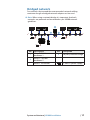
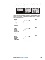
Bridged network
For networks that exceed the recommended network cabling
maximum length a bridged network adaptor can be used.
Note: When using a network bridge it is important that both
networks are powered and terminated as per H5000 network
guidelines.
12V
3
1 2
T
T
T
12V 12V
T
PILOT
No. Description No. Description
1Micro-C CAN bus
backbone 1 33rd party network bridge
2Micro-C CAN bus
backbone 2
TMicro-C Terminator 12V 12 Volt DC power supply

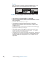
18 | System architecture | H5000 Installation
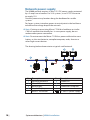
Network power supply
The H5000 network requires its own 12 V DC power supply protected
by a 5 amp fuse or breaker. For 24 V systems, use a DC-DC converter
to supply 12 V
Connect power at any location along the backbone for smaller
systems.
For larger systems introduce power at central point in the backbone
to balance the voltage drop of the network.
Note: If joining to an existing Micro-C CAN bus backbone or similar
CAN bus network that already has its own power supply, do not
make another power connection.
Note: Do not connect the Micro-C CAN bus power cable to the same
battery as the start batteries, autopilot computer, radar, thruster or
other high current devices.
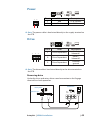
The drawing below demonstrates a typical small network.
12V
1
T T
5
2
34
6
P
T
12V
12V
7
No. Description No. Description
1Network backbone 5H5000 CPU
2Micro-C T-Joiner 6Sensor
3Race display 7H5000 Pilot Computer
4Graphic Display
TMicro-C Terminator 12V 12 Volt DC power supply

| 19
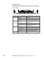
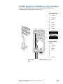
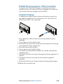
H5000 Central Processor Unit - CPU | H5000 Installation
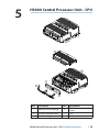
H5000 Central Processor Unit - CPU
1
2
3
4
5
6
No. Description No. Description
1Grommet retaining clip 4CPU lid with 6 x captive
screws
210 hole cable grommet 5CPU
35 hole cable grommet 6CPU terminals
5

20 | H5000 Central Processor Unit - CPU | H5000 Installation
Status LEDs
On the top of the CPU there are 4 diagnostic / status LEDs. These
LEDs will ash or change color to indicate system status as detailed in
the table below
POWER USB ETHERNETNETWORK
LED STATUS DESCRIPTION
POWER
No light No power
Solid green Power on
Solid red Voltage too high or too low
NETWORK
No light or not
ashing
No data being received or
transmitted
Flashing green Data being transmitted
Solid red Network not in use or
hardware error
USB
No light Default state when not in use
Flashing green Software upgrade in progress
Solid green Software upgrade successful
Solid red Software upgrade failed
ETHERNET Flashing green Data being transmitted
Page is loading ...
Page is loading ...
Page is loading ...
Page is loading ...
Page is loading ...
Page is loading ...
Page is loading ...
Page is loading ...
Page is loading ...
Page is loading ...
Page is loading ...
Page is loading ...
Page is loading ...
Page is loading ...
Page is loading ...
Page is loading ...
Page is loading ...
Page is loading ...
Page is loading ...
Page is loading ...
Page is loading ...
Page is loading ...
Page is loading ...
Page is loading ...
Page is loading ...
Page is loading ...
Page is loading ...
Page is loading ...
Page is loading ...
Page is loading ...
Page is loading ...
Page is loading ...
Page is loading ...
Page is loading ...
Page is loading ...
Page is loading ...
Page is loading ...
Page is loading ...
Page is loading ...
Page is loading ...
Page is loading ...
Page is loading ...
Page is loading ...
Page is loading ...
Page is loading ...
Page is loading ...
-
 1
1
-
 2
2
-
 3
3
-
 4
4
-
 5
5
-
 6
6
-
 7
7
-
 8
8
-
 9
9
-
 10
10
-
 11
11
-
 12
12
-
 13
13
-
 14
14
-
 15
15
-
 16
16
-
 17
17
-
 18
18
-
 19
19
-
 20
20
-
 21
21
-
 22
22
-
 23
23
-
 24
24
-
 25
25
-
 26
26
-
 27
27
-
 28
28
-
 29
29
-
 30
30
-
 31
31
-
 32
32
-
 33
33
-
 34
34
-
 35
35
-
 36
36
-
 37
37
-
 38
38
-
 39
39
-
 40
40
-
 41
41
-
 42
42
-
 43
43
-
 44
44
-
 45
45
-
 46
46
-
 47
47
-
 48
48
-
 49
49
-
 50
50
-
 51
51
-
 52
52
-
 53
53
-
 54
54
-
 55
55
-
 56
56
-
 57
57
-
 58
58
-
 59
59
-
 60
60
-
 61
61
-
 62
62
-
 63
63
-
 64
64
-
 65
65
-
 66
66


B&G H5000 Pilot Installation guide
- Category
- Processors
- Type
- Installation guide
Ask a question and I''ll find the answer in the document
Finding information in a document is now easier with AI


