Page is loading ...

Hoval United Kingdom
Hoval Ltd.
Northgate
Newark
Nottinghamshire NG24 1JN
Phone +44 1636 67 27 11
Fax +44 1636 67 35 32
Hoval Export
Hoval Aktiengesellschaft
Austrasse 70
9490 Vaduz
Principality of Liechtenstein
Phone +423 399 24 00
Fax +423 399 24 11
Subject to modifi cations | EN
Operating Instructions
UltraGas® (15-1000)
Condensing gas heating boiler
UltraGas® (15-90) UltraGas® (125-720)
UltraGas® (850-1000)
4 210 265 / 00 - 07/11

4 210 265 / 002 Table of contents
1. For an optimal use of the heating system, read the operating instructions!
1.1 Important addresses and telephone numbers .......................................................................................................3
1.2 Key to symbols used ................................................................................................................................................3
1.3 System data ............................................................................................................................................................... 4
1.4 Calculation basis ......................................................................................................................................................4
2. Safety information
2.1 Safety precautions ..................................................................................................................................................... 5
2.2 Intended use ............................................................................................................................................................... 5
3. Customer service
4. Functional principle of the heating system
5. System start-up
5.1 Checks prior to start-up ...........................................................................................................................................8
5.2 Switching on the system ........................................................................................................................................... 8
6. Heating system control
6.1 What is the function of the heating controller TopTronic® T? ................................................................................9
6.2 How you can save energy ........................................................................................................................................9
6.3 Basic display .............................................................................................................................................................9
6.4 Operating and display elements ............................................................................................................................ 10
6.4.1 Function of the operating elements............................................................................................................................10
6.4.2 Basic procedure for changing settings ....................................................................................................................... 10
6.4.3 What to do if... ............................................................................................................................................................11
6.4.4 Control elements on the boiler control panel ............................................................................................................12
6.5 Main settings ............................................................................................................................................................14
6.5.1 Changing the room temperature ............................................................................................................................14
6.5.1.1 Setting the daytime room temperature ..............................................................................................................................................14
6.5.1.1 Setting the reduced (night time) temperature....................................................................................................................................15
6.6 Operating modes .....................................................................................................................................................16
6.6.1 Operating mode functions .......................................................................................................................................... 16
6.6.2 Operating modes for holiday and absence? ..............................................................................................................17
6.6.3 Changing the operating mode - for “HOLIDAY TIL”, “ABSENT TIL” and “PARTY TIL” ................................................18
6.6.4 Changing operating mode - for “AUTOMATIC”, “SUMMER” , “HEATING”, “RED. HEATING” and “STANDBY” ..........19
6.7 Switching times (heating times) .............................................................................................................................20
6.7.1 Standard heating times ..............................................................................................................................................20
6.7.2 Table for recording individual switching times ............................................................................................................20
6.7.3 Changing the switching times (heating times) ...........................................................................................................21
6.7.4 Copying switching times.............................................................................................................................................24
6.8 Heating curve ...........................................................................................................................................................26
6.8.1 Heating curve (heating characteristic) information.....................................................................................................26
6.8.2 Changing the heating curve (heating characteristic) .................................................................................................27
6.9 Domestic hot water .................................................................................................................................................. 28
6.9.1 Adjusting the domestic hot water temperature ........................................................................................................... 28
6.9.2 Manual hot water loading ...........................................................................................................................................29
6.9.3 Domestic hot water economy temperature (reduced temperature)............................................................................30
6.10 Further settings ......................................................................................................................................................32
6.10.1 Setting the clock ......................................................................................................................................................... 32
6.10.2 Setting the date .......................................................................................................................................................... 33
6.10.3 Changing between summer and winter time ..............................................................................................................33
6.10.4 Setting the language ..................................................................................................................................................34
6.10.5 Reloading the standard switching times program - Deleting the own time program ..................................................35
6.10.6 Manual operating mode ............................................................................................................................................37
6.10.7 Alarms ........................................................................................................................................................................38
6.10.8 Changing the maximum boiler temperature ...............................................................................................................39
6.11 System information .................................................................................................................................................41
6.11.1 Information key for system temperatures and heating circuit information .................................................................. 41
6.11.2 Special symbols .........................................................................................................................................................42
6.11.3 Maintenance message ............................................................................................................................................... 42
6.11.4 Optional accessories .................................................................................................................................................42
7. Check list in case of faults
8. Controlling the water level
9. How you can save energy!
10. Hoval Service / Sales program

4 210 265 / 00 3
Operating instructions
1. For an optimal use of the heating system, read the operating instructions!
These instructions will provide you with all the information you need for an
optimal use of your heating system.
An optimally adjusted heating system can not only save you a lot of grief, but
also a lot of money.
1.1 Important addresses and telephone numbers
Heating installer: ......................................................................
......................................................................
Plumbing installer: ......................................................................
......................................................................
Electrical installer: ......................................................................
......................................................................
Chimney sweep: ......................................................................
......................................................................
Fuel supplier: ......................................................................
......................................................................
1.2 Key to symbols used
i
Instruction: Prompts you to carry out an action
Result: Shows the expected reaction to your action
Note: Provides important information
Safety information: Indicates an immediate hazard to persons
Warning information: Indicates danger to machines and installations
Energy saving tip: Provides energy saving information
ENERGY

4 210 265 / 004 Operating instructions
1.3 System data
To be completed by the heating installer!!
Order no.: .....................................................................
Boiler type: .....................................................................
Heating pump type: .....................................................................
Heating controller type: .....................................................................
Mixer type: .....................................................................
Calorifier type: .....................................................................
DHW sensor Yes No
Thermostat Yes No
Type of gas: Natural Gas H
Natural Gas L
Liquid Gas
Neutralisation unit Yes No
Condensate pump Yes No
Outside temperature sensor Yes No
Room temperature sensor Yes No
Combustion air supply Room Outdoor
Number of heating circuits: 1 2
3 4
Heating circuit HC = .....................................................................
Heating circuit MC1 = .....................................................................
Heating circuit MC2 = .....................................................................
Heating curve value HC = ....................................................................
Heating curve value MC1 = ..................................................................
Heating curve value MC2 = ...................................................................
1.4 Calculation basis
Lowest outdoor temperature: ................................................................ °C
Heat demand: .................................................................... kW
Max. flow temperature: .................................................................... °C

4 210 265 / 00 5
Safety information
2. Safety information
In the event of danger!
Cut off the fuel (gas) and electricity supplies
If you smell gas!
Do not smoke
No open fire
Avoid the occurrence of sparks
Do not switch on the light or other electrical appliances
Open windows and doors
Close the gas stop cock
Notify the heating company / installing contractor
Follow the safety regulations on the gas meter
Follow the safety regulations of the heating company
If you smell gas!
Turn the system off
Open windows and doors
Notify the heating company
Venting openings
Air inlets and outlets may not be closed. Closed venting openings can lead to in-
complete combustion and possible poisoning.
Exception: Your system operates room sealed - see page 4
Commissioning of a newly installed system may only be carried out by a qualified
installer. The installation control must be completed prior to commissioning -see
chapter 5.
2.1 Safety precautions
Checking the water level - see page 44
Commissioning of a newly installed system may only be carried out by a quali-
fied installer. The installation control must be completed prior to commissioning
-see chapter 5.
Maintain the room in which the boiler is held always clean and turn off the
burner before starting the cleaning to avoid any faults due to dusty combu-
stion air
2.2 Intended use
Intended use:
The UltraGas® boiler may only be operated with the fuels indicated in the
Information/Installation instructions.
The heat produced must be carried away by the heating water. All boiler ope-
nings must be closed during operation.
i

4 210 265 / 006 Customer service
The following information should be read before starting up the boiler!
Dear Customer,
With the Hoval UltraGas® you have acquired a product manufactured according to
the state-of-the-art and highest quality standards.
Please ensure that the delivery is consistent with your order and check it for com-
pleteness. Also check for possible damages during transport and inform the nearest
Customer Service centre about them. For insurance reasons it will not be possible
to accept any subsequent claims.
For the correct installation and operation of your Hoval UltraGas®, all applicable laws,
regulations and standards must be complied with; in particular the regulations of per-
tinent the energy supply company. In case of queries, please contact your specialist
installer or the nearest Hoval Customer Service centre.
Assembly or installation of the heating boiler may only be carried out by trained
personnel of a licensed installation company. Before starting the boiler for the first
time, an installation inspection and approval of the overall installation by the installer
are required.
To guarantee safe and trouble-free operation, operate your Hoval boiler only according
to these operating instructions.
The boiler may only be used for its intended purpose and fuels for which it is suitable
on the basis of its design and for which it has been approved by Hoval.
Do not carry out any changes to the system, otherwise all claims under the guarantee
will be waived. Conversion kits are to be installed and the installation approved by
authorised installers or by the Hoval Customer Service.
The reliable and safe functioning of a gas boiler, as well as the achievement of an
optimal effectiveness and clean combustion are only possible and guaranteed if the
system is maintained and cleaned at least once every year.
In the event of a fault or in case of damage, please contact the Hoval Customer
Service to inquire about the necessary repairs. In the meantime, shut down the unit
to avoid any damages.
With the acquisition of a Hoval unit you also obtain a comprehensive guarantee pro-
tection, as indicated in the guarantee conditions of the guarantee pass for your unit.
This guarantee is, however, dependent on the observance of the operating and instal-
lation instructions and on compliance with the applicable legal regulations. Non-com-
pliance with the above will invalidate all liability and warranty claims against Hoval.
Provided it is used correctly, your Hoval boiler will ensure you enjoy a well heated
home for many years.
The Hoval Customer Service
If you have any doubts in regard to the operation of your Hoval boiler, or minor faults
affect its correct functioning, please contact the nearest Hoval Customer Service
centre. A telephone call is often enough when it comes to solving small problems.
Our trained Customer Service staff will do everything in their hands to help you.
If a fault can not be solved in this way, a service technician will visit you in order to
solve the problem. We hope you understand that, except in urgent cases, this is not
always immediately possible.
Make use of the Hoval Customer Service offerings to lengthen the life of your boi-
ler.
3. Customer service
i

4 210 265 / 00 7
Functional principle of the heating system
4. Functional principle of the heating system
Components Function
Gas heating boiler Burns natural gas safely and environmen-
tally friendly. Extracts the heat from the ge-
nerated combustion gases and transfers
it to the heating water.
Calorifier It holds a reserve of domestic hot water
for consumption (e.g. for showering).
Boiler control unit
Controls and monitors the operation of the
heating boiler. Maintains the desired room
temperature optimally and fuel efficiently,
independently of the outside temperature
.
Radiator, floor heating Releases the heat of the heating water
into the room.
Heating pump Transports the heating water from the
heating boiler to the radiators and back to
the heating boiler, where it is reheated.
Mixing valve Adjusts the heating flow temperature by
admixing colder return water (water flow-
ing to the radiator) to maintain the desired
room temperature, independently of the
outside temperature.
Pressure gauge Displays the hydraulic pressure in the
heating system.
Air bleeder Eliminates any air to make sure that the
system contains only heating water.
Safety valve Prevents an overpressure in the system.
Diaphragm expansion tank Maintains the pressure in the system con-
stant.

4 210 265 / 008 System start-up
i
5. System start-up
Commissioning of a newly installed system may only be carried out by a qualified
installer. A full installation check must be completed prior to start-up.
- Set the main SYSTEM switch to “0”
- Open the shut-off valves in the flow and return lines.
- Open the gas shut-off cock in the boiler supply line
- Switch on the main switch outside the boiler room (if present).
Frequently, the heating system has an additional emergency switch that
switches off only the gas burner.
- With the UltraGas
®
, fill the odour trap (siphon) in the condensate drain
pipe with water before starting up the system.
5.1 Checks prior to start-up
Check the water level in the heating system.
The heating system must be filled with water and all the air removed. Observe the
regulations regarding antifreeze and water treatment.
Open the shut-off valves in the flow and return lines.
Check the fresh air supply to the heating system.
Check the settings for the operating modes
5.2 Switching on the system
Open the gas cock.
Switch on the main switch on the boiler.
Set the boiler control unit to the desired operating mode and temperature
i
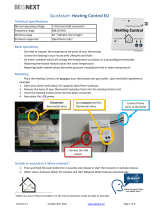
Depending on the working principle of the heating system selected, there may be extra components or
some may not be provided. Have your system explained in detail by the specialist.
Radiator(s) or
underfloor heating
where fitted
Heating pump
Heating boiler
Mixer valve
Water
heater
Chimney, flue
system
The hot water heated by the heating boiler is conveyed to the radiators, or is used to heat the domestic
hot water in the water heater.

4 210 265 / 00 9
Heating system control
6.1 What is the function of the heating controller TopTronic® T?
The boiler controller is, in conjunction with the temperature sensor connected
to it, so to speak, the brain of the heating system. Its main functions are:
- maintaining the desired room temperature independently of the outdoor
temperature
- heating the living space when required
- produce warm water (e.g. for showering) only when required
- displaying information
further functions:
- Input of desired temperatures and operating modes
- Turn the burner ON/OFF
- Temperature monitor
The correct settings for the heating system have already been applied by
Hoval, or the installer, during commissioning. Any changes to those settings
should only be carried out if you go away on a trip or if your home is to cold or
too warm. An overview of the most frequent questions/answers can be found
on pages 11 and 16 of these instructions.
6.2 How you can save energy
For your benefit and for the environment
Using energy more efficiently by avoiding unnecessary losses:
With little effort you can optimise the operation of your system and make it
worth while.
- You can save money. Enough money to pay your oil or gas bill every sixth
year
- Every year, you can save the energy equivalent of a bathtub full or heating
oil
In autumn, it is worth while turning the heating off again on warm days
This prevents the heating system from producing unnecessary heat in the
morning, due to low outdoor temperatures, and overheating the house. Turning
the heating on or off depending on the weather conditions is one of the most
effective energy saving measures. If you want to save yourself going down
the basement, you may want to consider acquiring a “remote control” from
Hoval, which will allow you to operate and control the heating comfortably
from your living room.
6.3 Basic display
The basic display shows the day of the week, date and time of the day, as well
as the current boiler temperature and room temperature (room station)
6. Heating system control
i
i
i
ENERGY

4 210 265 / 0010 Heating system control
6.4 Operating and display elements
6.4.1 Function of the operating elements
The central rotary pushbutton and the labelled keys are designed for easy
and straightforward operation.
Rotary pushbutton:
Change and store
values
6.4.2 Basic procedure for changing settings
An example
Select the desired function
Turn the rotary pushbutton to se-
lect or change the desired para-
meter (flashing word or number)
Press the Info key at any time to
go back to the basic display wi-
thout storing the values set
Press the rotary pushbutton to
store the value set
It is also possible to store the value
using the selected function key
Function keys
Function keys

4 210 265 / 00 11
Heating system control
Observation
It is too cold
It is too warm
From now on, equal day and
night temperatures should be
maintained continuously
This evening, the heating
should remain on for longer
A larger amount of hot water
is required
From now on, hot water but no
heating is required
Suddenly, there is no heating
or hot water; it is cold.
The room temperature setpoint
requires frequent adjustments
because it is too cold or too
hot
Today, I will be absent for seve-
ral hours during the day
I am travelling for a short peri-
od of time (e.g. 3 days)
I will be travelling for an inde-
finite period of time
In summer, it is too cold or too
warm.
Remedy
Set a higher value for the room temperature with and
the rotary pushbutton (page 14).
Set a lower value for the room temperature with and
the rotary pushbutton (page 14).
Set the operating mode to “HEATING” with (page 16,
19).
Set the operating mode to “PARTY” with and set the
desired time (page 16, 18).
Press for 3 seconds and set the additional loading time
(page 29).
Set operating mode to “SUMMER” with (heating off, only
hot water) (page 16, 19).
Check the boiler controller for alarms and consult a heating
engineer, if necessary. Check main switch (see page 12) and
gas supply
Change the set heating curve (page 27, 28).
Changing the heating curve is not sensible if your system is fitted
with a room sensor (or room station) and an outdoor sensor.
The correct settings for the heating curve are then provided
automatically. Consult a specialist, if necessary.
Set the operating mode to “ABSENT TIL” with and set
the return time (page 16-18).
Set the operating mode to “HOLIDAY TIL” with and set
the return date (page 16-18).
Set the operating mode to “RED. HEATING” with .
When returning, set the operating mode to “AUTOMATIC” (page
16, 17, 19) .
Indicates that the summer disconnection is active. Wenn
Ihnen If it is too cold, set the operating mode to “HEATING”
with (page 16, 19).
���
���
���
���
���
���
���
���
6.4.3 What to do if...
The following information can be used as a first level support in frequently
occurring situations.

4 210 265 / 0012 Heating system control
6.4.4 Control elements on the boiler control panel
1
5
910
Key Designation Function
1
Main switch
I = ON Boiler and illumination of Hoval logo in op-
eration
0 = OFF Boiler and burner are shut down
! Attention: No frost protection
2Daytime room temperature Set the daytime room temperature. Page 14
3Reduced room tempera-
ture
Set the night time room temperature (reduced hea-
ting). Page 15
4DHW temperature Set the domestic hot water temperature. Manual DHW
reloading. Page 28, 29
5
Rotary pushbutton Change the values by turning. Confirm the values by
pressing. Function selection by pressing and turning.
6
Information key
• Show the operating data on the display.
•
Return to the basic display without saving the values
.
See example on page 41
7Heating curve set-up Set the heating characteristics Page 27, 28
8 67 A 2nd electronic heating
controller can be installed
here (for 2nd home), if
required.
23412
11 13
14

4 210 265 / 00 13
Heating system control
Key Designation Function
8
Operating mode selection key
Select the operating modes
Holiday Turn off the heating system during the holidays (frost
protection) Page 16-18
Absence Temporarily switch off heating Page 16-18
Party Extended heating Page 16,18
Automatic Automatic heating according to the preset heating
times = normal heating Page 16,19
Summer only DHW; heating off Page 16,19
Constant heating
Constant heating mode Page 16,19
Reduced heating
Constant reduced heating mode Page 16,17,19
Standby
System switched off - Frost protection activated
Page 16,17,19
9
���
Manual mode / emission
measurement
For heating technician only or for preliminary acknowl-
edgement of a maintenance prompt (see chapter
6.11.3).
10 Display The basic screen shows the day of the week, date
and time of the day, as well as the current heat pro-
duction temperature or another temperature (system
dependent).
2
1
3
4
6
7
5
Possible readouts:
1 Active heating time 24h
2 Weekday display
3 Display of the active operating mode and the clock
programme
4 Time of the day
5 Selected operating mode
6 Date / Day / Month / Year
7 Heat production temperature or another tempera-
ture (system dependent).
11 Control panel fuse under
the hinged cover
Check the 6.3 A fuse if the display 11 stays dark. This
should only be done by the heating technician!
12 Reset button under the
hinged cover
Press the Reset button under the hinged cover if the
display shows “Error”. If this happens frequently, notify
your Customer Service centre.
13 Brief operating instructions
on the hinged cover
Special brief operating instructions are provided with
the heating control.
14 Burner error lamp Press the Reset button (see no. 12)
���

4 210 265 / 0014 Heating system control
6.5 Main settings
6.5.1 Changing the room temperature
6.5.1.1 Setting the daytime room temperature
Start - Basic display
Tap the “Daytime room tempera-
ture” key.
The daytime room temperature set-
point flashes.
Set the desired room temperature
by turning the “rotary pushbutton”.
The new “Daytime room tempera-
ture” setpoint appears on the dis-
play.
Tap the “Daytime room tempera-
ture” key to confirm the tempera-
ture setpoint.
MO. 16. AUG.'04
14:00 62.5C
ROOM DAY
20.0C
ROOM DAY
22.0C
These adjustments can also be
carried out on a room station.
If “MC1” is shown on the display,
you need to select the heating cir-
cuit. (Information on which heating
circuit to select for your home can
be found on page 4 of these in-
structions).
i
i
1
2
3
4
5
6
Setting range 5 - 30ºC
(Factory setting 20ºC)
i

4 210 265 / 00 15
Heating system control
6.5.1.1 Setting the reduced (night time) temperature
MO. 16. AUG.'04
14:00 62.5C
ROOM NIGHT
20.0C
ROOM NIGHT
18.0C
1
2
3
4
5
6
Start - Basic display
Tap the “Reduced room tempera-
ture” key.
The night time room temperature
setpoint flashes.
Set the desired room temperature
by turning the “rotary pushbutton”.
The new “Reduced room tempera-
ture” setpoint appears on the dis-
play.
Tap the “Reduced room tempera-
ture” key to confirm the tempera-
ture setpoint.
If “MC1” is shown on the display,
you need to select the heating
circuit. (Information on which hea-
ting circuit to select for your home
can be found on page 4 of these
instructions).
i
Setting range 5 - 30ºC
(Factory setting 16ºC)
i

4 210 265 / 0016 Heating system control
Operating mode
HOLIDAY
ABSENT
PARTY
AUTOMATIC
SUMMER
HEATING
RED. HEATING
STANDBY
Function
- Heating system off during holidays.
- Room temperature set to minimum (10ºC).
- Calorifier frost protected (5ºC).
- Heating system OFF
(heating temporarily switched off until set
time).
- Room temperature set to minimum (10ºC).
- Calorifier frost protected (5ºC).
- Extend heating (daytime room temperature)
up to set day/night time (you do not want to
reduce the room temperature at the preset
time).
- Automatic heating mode according to the
heating times set in the 1.switching time pro-
gram = normal heating mode.
- Heating system OFF
- DHW is produced at the times set in the swit-
ching time program (for showering, etc.)
- Frost protection active.
- The room temperature is not reduced during
the night.
- The rooms are continuously heated at the
set “daytime room temperature” .
- DHW mode according to switching program.
- The rooms are continuously heated at the
set “reduced room temperature” .
- Continuous reduced heating mode.
- Heating system OFF.
- Frost protection active.
- No DHW mode.
6.6 Operating modes
6.6.1 Operating mode functions
Application
You go on holiday for e.g. 1 week and you
know the return date.
Page 17,18
You leave home in the morning and come
back in the evening.
Page 17,18
You have guests in the evening.
Page 18
You want to heat as cost effectively and effi-
ciently as possible.
Page 19
Heating the rooms is unnecessary due to
the high outdoor temperatures.
Page 19
You prefer to heat the rooms also during the
night.
Page 19
You are travelling for an indefinite period of
time.
Page 17,19
You are travelling for an indefinite period of
time in spring or in autumn. It does not mat-
ter if the rooms are cold on return. You need
warm water on return. Page 17,19
iEnd of holiday = Return date Normal heating is resumed on the day of return!
Setting range: current date + 250 days.
To switch over to automatic mode prematurely
���
press the “operating mode” key for 3 sec.
i
Setting range: 0.5 - 24 h.
To switch over to automatic mode prematurely - press the “operating mode” key
���
for 3 sec.
iSetting range: 0.5 - 24 h.
To switch over to automatic mode prematurely - press the “operating mode” key
���
for 3 sec.
iFactory setting:
Heating: 06.00 - 22.00 Uhr
Reduced heating: 22.00 - 06.00 Uhr
Domestic hot water: 05.00 - 22.00 Uhr
i
Factory setting for domestic hot water: 05:00 - 22:00
Operating mode “Summer” can not be selected if each heating circuit is adjusted separately.

4 210 265 / 00 17
Heating system control
Function
- Heating system OFF / Calori-
fier frost protected (5°C)
- Room temperature set to mini-
mum (10°C)
Setting range:
current date + 250 days !
End of holiday = Return date
Normal heating is resumed on
the day of return!
Early return:
“Press” for 3 sec. to return
to “AUTOMATIC” mode (see
page 16, 18).
Heating temporarily interrupted
until set time.
Setting range: 0.5 - 24h
Continuous reduced heating and
DHW mode (reduced see page
30, 31) around the clock.
The entire heating system is
switched off and frost protected.
Calorifier frost protected!
6.6.2 Operating modes for holiday and absence?
Depending on the duration of your absence and what your requirements are in
regard to comfort, there are different operating modes available for interrupting or
reducing the heating. In any case you will be able to save a lot of energy and money
if the rooms are not heated or less heated during your absence.
The following table is intended as a guide for finding the best operating mode for
each particular case:
���
See following pages for a detailed description on how to set the operating modes.
You can return to the “AUTOMATIC” function (normal heating mode) at any time by “pressing” for 3
sec.
���
Application
You go on holiday for e.g. 1
week and you know the return
date.
You leave home in the mor-
ning and come back late in
the evening.
You are travelling for an inde-
finite period of time and want
the living area to be at the set
reduced temperature on re-
turn.
You are away for an indefinite
period of time during spring or
autumn and you don’t mind if
your home is cool on return.
Operating mode
"HOLIDAY TIL"
Heating system and DHW off
during holidays.
"ABSENT TILL"
Heating interrupted temporarily
"RED. HEATING"
Continuous reduced heating mode
"STANDBY"
System switched off - Frost
protection activated

4 210 265 / 0018 Heating system control
Tap the “Operating mode” key.
The note “OP. MODE” is displayed
for a short time.
The currently active operating
mode is then shown flashing on the
display.
Set the desired operating mode by
turning the “rotary pushbutton”:
The selected operating mode (e.g.
“HOLIDAY TIL” is shown flashing on
the display.
Tap the “rotary pushbutton” to con-
firm the selected operating mode.
Today’s date (“HOLIDAY TIL”) or
the current time (“ABSENT TIL”,
“PARTY TIL”) is shown flashing on
the display.
Turn the “rotary pushbutton” and
select:
Tap the “rotary pushbutton” to con-
firm the setting.
6.6.3 Changing the operating mode - for “HOLIDAY TIL”, “ABSENT TIL” and “PARTY TIL”
Procedure for activating the operating modes “HOLIDAY TIL”, “ABSENT TIL” or
“PARTY TIL”.
OP. MODE
AUTOMATIC
HOLIDAY TIL
HOLIDAY TIL
27.08
���
1
2
3
4
5
6
A black rectangle at the lower part
of the display points to the corre-
sponding symbol!
i
7
8
9
- for “HOLIDAY TIL”, the date of re-
turn from holiday.
- for “ABSENT TIL”, the expected
return time (within max. 24h).
- for “PARTY TIL”, the time the par-
ty is expected to end.
i
“HOLIDAY TIL”,
“ABSENT TIL” or
“PARTY TIL”.
i

4 210 265 / 00 19
Heating system control
6.6.4 Changing operating mode - for “AUTOMATIC”, “SUMMER” , “HEATING”, “RED. HEATING” and
“STANDBY”
Procedure for activating the operating modes “AUTOMATIC”, “SUMMER” , “HEA-
TING”, “RED. HEATING” and “STANDBY”
Follow the steps 1 to 3 described
in chapter 6.6.3 “Changing the
operating mode” on page 18!
Set the desired operating mode by
turning the “rotary pushbutton”:
The selected operating mode (e.g.
“RED. HEATING” is shown flashing
on the display.
Tap the “rotary pushbutton” to con-
firm the setting.
RED. HEATING
4
5
6
“AUTOMATIC”,
“SUMMER”,
“HEATING”,
“RED. HEATING”
or “STANDBY”.
i

4 210 265 / 0020 Heating system control
... pro Tag
1 Heizzyklus!
... pro Tag
2 Heizzyklen!
... pro Tag
3 Heizzyklen!
... pro Tag
1 Heizzyklus!
... pro Tag
2 Heizzyklen!
... pro Tag
3 Heizzyklen!
6.7 Switching times (heating times)
In this menu the switching time programs can be set individually for the hea-
ting and DHW modes.
The standard heating times preset by the manufacturer are overwritten. You
can, however, easily restore these at any time (see pages 35, 36).
It is possible to program up to 3 heating times per day.
The switching times are only active when the “AUTOMATIC” mode is se-
lected.
6.7.1 Standard heating times
Circuit Day Heating from-to
All heating circuits (HC,MC-1,MC-2)
Mo-So 06.00 - 22.00
Hot water circuit (DHW) Mo-So 05.00 - 22.00
Further standard programs can be - or could have been - set-up or enabled for programming by the
installer (P1-P3) see page 23.
A maximum of 3 heating times per
day are possible, e.g.:
6.7.2 Table for recording individual switching times
Switching times program for living area...............
(MC1)
Day
Cycle 1 Cycle 2 Cycle 3
from to from to from to
Mo
Di
Mi
Do
Fr
Sa
So
Switching times program for living area..............
(MC2)
Day
Cycle 1 Cycle 2 Cycle 3
from to from to from to
Mo
Di
Mi
Do
Fr
Sa
So
Switching times program for living area..............
(HC)
Day
Cycle 1 Cycle 2 Cycle 3
from to from to from to
Mo
Di
Mi
Do
Fr
Sa
So
Switching times program for calorifier
(DHW)
Day
Cycle 1 Cycle 2 Cycle 3
from to from to from to
Mo
Di
Mi
Do
Fr
Sa
So
i
i
i
i
per day
1 heating cycle
per day
2 heating cycles
per day
heating cycles
/