Page is loading ...

KVH, TracPhone, TracVision, and the unique light-colored dome with dark contrasting baseplate (Reg. No. 2,864,752) are
registered trademarks of KVH Industries, Inc. All other trademarks are property of their respective companies. The information in
this document is subject to change without notice. No company shall be liable for errors contained herein.
© 2021-2022 KVH Industries, Inc., All rights reserved. 54-1399 Rev. C | 72-0955-01/72-0956-01 1
TracPhone V30
Mounting Inside a TV5/TV6-sized Dome
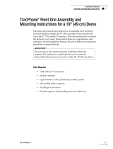
The following instructions explain how to install the TracPhone® V30 antenna inside a TracVision® TV5 or TV6-sized
dome.
Tools Required
In addition to all of the items provided in this kit, as well as
the V30 antenna installation kit and tools list, this
procedure requires the following tools and materials that
are not supplied:
• Flat-head and Phillips screwdrivers
• Torque wrench and sockets
• Socket wrenches
• Electric drill and drill bit:
TV5 dome: 3/8" (10 mm)
TV6 dome: 1/2" (13 mm)
• 1.5" (38 mm) hole saw
• Light hammer and center punch
• Adhesive tape
•Shop towels
• Self-vulcanizing tape or equivalent
• Silicone sealant or equivalent
Steps
Prepare the Mounting Site .................................................2
Mount the TV5/TV6-sized Baseplate .................................2
Install the V30 Inside the TV5/TV6-sized Baseplate ..........3
IMPORTANT!
These instructions assume that the TracPhone antenna
is not already mounted to the vessel. If it is mounted to
the vessel, you will first need to disconnect all power
from the antenna, detach it from the mounting surface,
and disconnect the cable.
Technical Support
Within Continental U.S.A.: 1 866 701-7103
Worldwide: +1 401 851-3806
Email: mvbsupport@kvh.com

2
Mounting V30 in TV5/TV6-sized Dome
Prepare the Mounting Site
Follow the same guidelines in the TracPhone V30
Installation Guide to choose a suitable mounting location
on the vessel. Then perform the steps below to prepare the
mounting site.
1. Unfold the antenna mounting template (supplied in the
TV5/TV6-sized dome kit) and place it onto the
mounting surface. Make sure the “FWD” (forward)
arrow points toward the bow and is parallel to the
vessel’s centerline (see Figure 1). Tape in place.
Figure 1: TV5/TV6-sized Dome Mounting Holes Layout
2. Using a light hammer and center punch, mark the
locations for the four mounting holes and cable access
hole on the mounting surface in the locations indicated
on the template.
3. Drill the four mounting holes at the locations you
marked in Step 2. Be sure to drill the correct size hole
for your dome size (TV5 or TV6) (see Figure 1).
4. Cut out a 1.5" (38 mm) cable access hole in the center
of the mounting bolt pattern. Smooth the edges of the
hole to protect the cable.
5. Clean and dry the antenna mounting surface.
6. Peel off the paper backing from the supplied foam seal
to expose the adhesive. Then press the foam seal
down firmly onto the mounting surface, ensuring the
hole in the foam seal aligns with the cable access hole
in the mounting surface.
Mount the TV5/TV6-sized Baseplate
1. Remove and save the #10-32 screws securing the
radome to the TV5/TV6-sized baseplate. Remove the
radome and set it aside in a safe place.
2. Place the TV5/TV6-sized baseplate over the holes
drilled in the mounting surface, making sure its
Forward arrow points toward the bow and is parallel
with the vessel’s centerline. The baseplate should rest
squarely atop the foam seal.
3. Apply a thin layer of the supplied anti-seize lubricant to
the threads of the four TV5/TV6 mounting bolts.
NOTE: The TV5-sized baseplate uses 1/4"-20 bolts. The
TV6-sized baseplate uses 3/8"-16 bolts.
4. At each of the four baseplate mounting holes, place a
flat washer on a mounting bolt and insert the bolt into
the hole from above (see Figure 2).
Figure 2: Mounting the TV5/TV6-sized Baseplate
5. Secure each mounting bolt to the mounting surface
using a flat washer and a lock nut from below. Tighten
all four bolts until the four rubber feet on the baseplate
are bottomed against the mounting surface and the
foam seal is fully compressed. For the TV5-sized
dome, tighten to approximately 60 in-lbs of torque. For
the TV6-sized dome, tighten to approximately 192 in-
lbs (16 ft-lbs) of torque.
Mounting Hole (x4)
TV5: Ø 3/8" (Ø 10 mm)
TV6: Ø 1/2" (Ø 13 mm)
Cable Access Hole
Ø 1.5" (Ø 38 mm)
TV5: 9" (229 mm)
TV6: 12" (305 mm)
TV5: 9" (229 mm)
TV6: 12" (305 mm)
Align Foam Seal
with Cable
Access Hole
FWD
CAUTION
Be sure to observe the safe handling
instructions in the Material Safety Data Sheet
(MSDS) provided with the anti-seize lubricant.
Mounting Bolt (x4)
Flat Washer (x4)
Rubber Foot (x4)
Mounting Surface
Flat Washer (x4)
Lock Nut (x4)
Antenna Baseplate
IMPORTANT: Apply
anti-seize to threads

3
Mounting V30 in TV5/TV6-sized Dome
Install the V30 Inside the
TV5/TV6-sized Baseplate
1. Remove and save the #10-32 screws securing the
radome to the V30 baseplate.
2. Remove the foam shipping restraints from the V30
antenna.
3. Route the antenna cable up through the cable access
hole in the mounting surface and the center of the
TV5/TV6-sized baseplate. Then connect it to the V30
antenna as directed in the V30 Installation Guide:
a. Make sure the antenna cable’s connector and the
cable connector on the bottom of the V30 antenna’s
baseplate are clean and dry.
b. Fill half of the inner body of the cable’s male
connector with the supplied silicone grease.
c. Connect and slowly hand-tighten the cable to the
V30’s baseplate connector.
d. Seal the cable connection with self-vulcanizing tape
or equivalent.
e. Secure the antenna cable near the antenna to
relieve stress.
f. Weatherproof and seal the cable access hole in the
mounting surface.
4. Carefully place the V30 onto the mounting platform
inside the TV5/TV6-sized baseplate. Align the V30’s
forward arrow with the TV5/TV6’s forward arrow.
5. Apply a thin layer of the supplied threadlocker to the
threads of the four 1/4"-20 V30 mounting bolts.
6. Secure the V30 antenna baseplate to the TV5/TV6
mounting platform using the 1/4"-20 bolts and flat
washers. Tighten to 60-65 in-lbs of torque.
7. Reinstall the radome onto the TV5/TV6-sized
baseplate. Secure in place with the #10-32 screws you
removed earlier. Hide and protect the screws with the
plastic screw caps.
Follow all remaining steps in the TracPhone V30
Installation Guide to complete the installation.
Figure 7: Mounting the V30 Inside the TV5/TV6-sized Dome
CAUTION
Be sure to observe the safe handling
instructions in the Material Safety Data Sheet
(MSDS) provided with the silicone grease and
threadlocker.
IMPORTANT!
You need to remove the radome from the V30 antenna
to mount inside a TV5/TV6-sized dome, but do not
remove the V30 antenna assembly from its baseplate.
1/4"-20 Bolt
& Flat Washer
Mounting Surface
TV5/TV6
Baseplate
Mounting Platform
Foam Seal
V30 Antenna
TV5/TV6-sized
Radome
Flat Washer
& Lock Nut
TV5: 1/4”-20
TV6: 3/8”-16
Bolt & Flat
Washer
TV5: 1/4”-20
TV6: 3/8”-16
/