Page is loading ...

Features
Conforms to EN54-2 and EN54-4 Standards*
Control panel hardware feature summary:
• 160 Character super-twist LCD readout
(4 lines x 40 characters/line)
• Membrane keypad with insert labels
• Expandable up to 512 points/32 zones
Supports conventional and addressable
inputs:
• MAPNET II
®
Addressable Devices including
isolator modules
• TrueAlarm
®
Addressable Analog Sensors**
• Nonvolatile flash EPROM memory
• Temperature compensated battery charger
• Battery supervision (low/no battery)
Software Features:
• Four operator access levels
• 300 Event historical alarm and fault logs
• Zonal and point alarm information
• Alarm resound feature
Programmable:
• Site specific programmable keys/LEDs
• Powerful custom control provides maximum
flexibility
Optional Voice Evacuation and Fire Brigade
phones:
• Single, dual, and triple channel
• Custom voice messages and tones
• 2-Way fire brigade voice communications
• 25 W and 100 W, 25 VRMS Amplifiers
Interface to Remote:
• MINIPLEX
®
Transponders
• 4604-9202UK Remote LCD Annunciator for
supplementary operations
Optional Modules:
• 4120 Network Interface
• Sounder outputs
• Conventional and addressable inputs
• Control relays with feedback
• Mimic panel modules
• Expansion power supplies
PULL DOOR TO OPEN
EMERGENCY OPERATING
INSTRUCTIONS
INDICATION OF ALARM, FAULT WARNING, OR DISABLED CONDITION:
- GENERAL VISIBLE INDICATOR AND AUDIBLE INDICATOR ON.
TO VIEW SUPPRESSED ALARM, FAULT, OR DISABLED INDICATIONS:
- PRESS "REVIEW" KEY LOCATED UNDER EACH VISIBLE INDICATOR.
- REPEAT UNTIL ALL SUPPRESSED INDICATIONS HAVE BEEN DISPLAYED.
TO SILENCE THE LOCAL AUDIBLE INDICATIONS:
- PRESS "PANEL SILENCE" KEY.
TO SILENCE THE ALARM SIGNALS:
- PRESS "SOUNDER" SILENCE/RESOUND" KEY.
TO RESTORE SYSTEM TO NORMAL:
-PRESS "RESET" KEY.
SYSTEM
FAULT
POWER
SITE SPECIFIC PROGRAMMABLE KEYS/LEDS
RESET
PANEL
SILENCE
FIRE
ALARM
REVIEW
ALARMS
FAULT
REVIEW
FAULTS
SOUNDER
FAULT/DISABLED
DISABLE/ENABLE
SOUNDERS
SOUNDERS
SILENCED
DISABLEMENT
REVIEW
DISABLED
ZONES
SOUNDER
SILENCE/RESOUND
*** System is Normal ***
09:36:24 MON 05-APR-1999
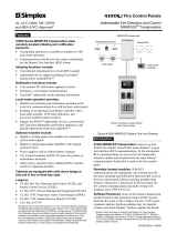
4100 FIRE ALARM CONTROL
4100/4120 Series Control and Indicating Equipment
(shown as a 6 unit panel with optional voice control)
Description
Simplex 4100/4120 Series Control and Indicating
Equipment provide an extensive and powerful feature
list to satisfy a wide variety of applications and local
requirements. They are on-site programmable to
provide mapping logic for inputs and outputs and for
custom labeling additions and revisions. Their flexible
site-specific software features can be quickly and
securely generated, modified, and archived by trained
service personnel using computer based programming
tools. With this flexibility, last minute changes can be
made on-site, minimizing delays in job completion.
Input point expansion is available up to a maximum of
512 points in any combination of input types.
NOTE: When these c.i.e. products are factory configured for 4120
Network Control panel operation, substitute 4100 for 4120.
Contact your local Simplex representative for additional
information about the 4120 Network.
* Refer to pages 6 and 7 for additional information on EN54 compatibility and
LPC testing status.
** MAPNET II addressable communications is protected under U.S. Patent #
4,796,025. TrueAlarm addressable smoke detection operation is protected
by one or more of the following U.S. Patents: 5,155,468; 5,173,683;
5,543,777; 5,400,014; 5,552,765; 5,552,763; DES. 377,460.
TrueAlarm
®
Fire Alarm Controls
EN54 Compliant* 4100 and 4120 Series Fire Alarm
Control and Indicating Equipment (c.i.e)
© 1999 Simplex Time Recorder Co. All rights reserved. S4100-0025 (EN54) 5/99

Operator Interaction
The illustration below identifies the LCD readout and
the primary operator indicators and switch functions.
When the internal access door is lowered, the additional
keypad shown is available for extended operator
functions. Some of the features include:
• Bright LED indicators and LCD alphanumeric
information for accurate status presentation
• Nomenclature that is provided by insert, allowing the
terminology to be revised to suit local language
needs
• Four site-specific programmable LEDs and switch
keys for use as required by the individual location
• Typical LCD information is displayed in sequence:
Line 1: First zone in alarm/Menu
Line 2: Menu information
Line 3: Most recent zone in alarm
Line 4: Total event counts
Password Access
Four levels of password protection are available.
Typical access divisions are per the following:
Operation Level
View software revision, test indicators
Access alarmed zones not shown
Display suppressed faults or disablements
1
Silence local sounder
Reset latching fault conditions
Silence fire alarm sounders
Resound fire alarm sounders
Initiate reset process
Disable/enable points, zones, or outputs
Set time and date, View historical logs
2
Clear historical logs, Manually control points and lists 3
Disconnect or adjust main or standby power
Modify program contents (EXEC)
Alter site-specific data (CFIG)
4
Simplex Time Recorder Co. 2 S4100-0025 (EN54) 5/99
SYSTEM
FAULT
POWER
ZN
1
SIG
2
AUX
3
FB
4
IO
5
MAP
6
P
7
A
8
ZONE
9
NET
-
FUNC
0
DEL
ENTER CLR
MENU
SITE SPECIFIC PROGRAMMABLE KEYS/LEDS
RESET
PANEL SILENCE
REVIEW
ALARMS
FIRE
ALARM
REVIEW
FAULTS
FAULT
DISABLE/ENABLE
SOUNDERS
SOUNDER
FAULT/DISABLED
SOUNDER
SILENCE/RESOUND
SOUNDERS
SILENCED
REVIEW
DISABLED
ZONES
DISABLEMENT
NEXT PREV
*** System is Normal ***
09:36:24 MON 05-APR-1999
4 X 40 LCD READOUT, LED backlighted during
normal conditions and abnormal operating
conditions, provides up to 40 characters for custom
label information
EXTENDED FUNCTION KEYPAD (accessible
with door open) select and scroll through display
prompts for locating additional system information,
performing maintenance functions
YELLOW FAULT LED flashes
when a new fault event is received,
REVIEW FAULTS KEY steps
through fault events
YELLOW DISABLEMENT LED
flashes when a new disablement
event is received, REVIEW
DISABLED ZONES KEY steps
through disabled zones
YELLOW SOUNDER FAULT LED flashes when there is a fault
on a sounder circuit and turns on steady when a sounder circuit
is disabled, DISABLE/ENABLE SOUNDERS KEY allows all
sounders to be disabled simultaneously
YELLOW SOUNDERS SILENCED LED turns
on to indicate that the sounder points have been
turned off, SOUNDER SILENCE/RESOUND
KEY silences the sounders when on and will
resound them when pressed again
RESET KEY initiates system reset process
PANEL SILENCE KEY turns off the local sounder
YELLOW SYSTEM FAULT LED turns on to indicate a system fault
GREEN POWER LED turns on whenever the c.i.e. is powered,
either mains or battery
FOUR PROGRAMMABLE
SWITCHES WITH YELLOW
LEDs provide custom operations
labeling (labels insert into a
pocket)
RED FIRE ALARM LED flashes when a
new alarm event is received and REVIEW
ALARMS KEY steps through alarm events
STATUS INDICATOR LEDs provide system status indications
in addition to LCD information, LEDs flash to indicate the
condition and change to steady on after one minute
Operator Control Panel Functions

Master Controller Module
The 4100/4120-7014 Master Controller Board provides
system control, synchronization, and supervision of all
modules, continuously scanning each module for status
changes. Features include:
• Operator’s Panel with LCD and operator keys
• General Fault Output
• General Alarm Output, form “C” contact output
• RS-232 Dual Port Communications Module,
one port is dedicated to control the user interface
panel, one port is unassigned (can be connected to
remote LCD Annunciator 4604-9202UK)
• Battery Charger for up to 110 Ah Batteries
– Batteries up to 42 Ah may be mounted in the bottom
of the control cabinet
– Batteries larger than 42 Ah mount external to main
control cabinet
• Intelligent Power Supply:
– Two isolated outputs of 4 Amps each at 28.5 VDC
when mains powered (24 VDC nominal during
battery operation)
– Tap “B” provides 4 A for general purpose sounder
circuits and control power
– Tap “A” provides 2 A (typical) for sounder circuits
controlling “clean” loads with controlled inrush
current and proper transient suppression (actual
available power depends on total system power
requirements)
Optional Modules Description
• Conventional Zone Circuits:
– Eight circuit zone modules provide system expansion
as Class B operation
– Capable of supporting two-wire Simplex smoke
detectors and electronic heat detectors plus normally
open contact devices (manual stations, mechanical
heat detectors, etc.)
• Sounder and Speaker Circuits:
– Two, four, or six circuit modules provide Class B
system expansion
– Circuit ratings: 2 A @ 24 VDC; 50 W @ 25 VRMS
(for speaker circuits), or for up to 6 telephones
– Supervised for opens, grounds, and wire-to-wire
shorts
– Dual and Triple channel modules have integral
switching relays for selecting the proper audio
channel output
– Outputs can be programmed for temporal code or
march time code
• RS-232 Dual Port Communication Module:
– Up to four additional RS-232 modules total
– Each port can be vectored by event category
• Auxiliary Control Relays:
– Built-in fuse protection per contact
– Feedback tracks on/off status of remote devices
– 4100-3001, four CPU controlled relays, DPDT
contacts rated for 2 A @ 24 VDC
– 4100-3002, four CPU controlled relays, DPDT
contacts rated 10 A @ 24 VDC
– 4100-3003, eight CPU controlled relays, SPDT
contacts rated 3 A @ 24 VDC
• LED Annunciation:
– Optional interface modules are available for remote
and/or local control panel annunciation. The LEDs
are programmable for slow rate, fast rate pulse, or
steady illumination.
• 64/64 LED/Switch Controller:
– Interfaces up to 64 LEDs and 64 switches to the
master controller via serial communications
– Continuously monitors switches for changes in status
– Supervises and controls LEDs
– Supervises LED/switch module placement
• 24 Point I/O Graphic Interface:
– Each of the 24 points can be individually configured
as either a switch input or a lamp driver output
– 150 mA lamp driver output (+24 VDC common)
– Outputs can be steady, slow pulse, or fast pulse
– Switch inputs can monitor two position or three
position switches
– Lamp test input
• LED/Switch Modules:
– Modules contain socketed LEDs to allow
interchanging with different color LEDs to indicate
function
– Switch modules can be used to perform manual
control such as for HVAC, pressurization fans,
damper control, speaker circuits, etc.
• MAPNET II
®
, TrueAlarm
®
Addressable
Module:
– Connections for up to 120 MAPNET II addressable
devices or TrueAlarm analog sensors per module
– MAPNET II Line Isolator Modules are available for
protecting Class A addressable circuit loops from
short circuits
• Remote Unit Interface (RUI) Modules:
– Provides a supervised serial communication channel
for control and monitoring of remotely located mimic
panels, MINIPLEX transponders, and I/O panels
Simplex Time Recorder Co. 3 S4100-0025 (EN54) 5/99

MINIPLEX
®
Distributed Module Operation
– Up to 31 MINIPLEX transponders can be controlled
from the c.i.e.
– Allows remote location of: amplifiers, MAPNET II
and TrueAlarm interface modules, conventional zone
circuits, sounder circuits, and auxiliary control
circuits
– Up to four RUI modules can be installed in the c.i.e.
4604-9202UK Remote LCD Annunciator
For supplementary applications, the model
4604-9202UK remote LCD annunciator provides an
informational display similar to that on the front of the
c.i.e. Details are as follows:
• Surface mounted, cabinet included
• LED backlighting for easy reading
• Backlighting is off during battery power except
during keypad activity (when activity ceases, the
backlighting will time out and again turn off)
• Connections are serial communications via RS-232
wiring
• Distance is up to 25 ft (7.6 m)
• Dimensions: 12 13/16” W x 9 7/8” H x 2 1/8” D
(325 mm x 251 mm x 54 mm)
SYSTEM
FAULT
POWER
ZN
1
SIG
2
AUX
3
FB
4
IO
5
MAP
6
P
7
A
8
ZONE
9
NET
-
FUNC
0
DEL
ENTER CLR
MENU
SITE SPECIFIC PROGRAMMABLE KEYS/LEDS
RESET
PANEL SILENCE
REVIEW
ALARMS
FIRE
ALARM
REVIEW
FAULTS
FAULT
DISABLE/ENABLE
SOUNDERS
SOUNDER
FAULT/DISABLED
SOUNDER
SILENCE/RESOUND
SOUNDERS
SILENCED
REVIEW
DISABLED
ZONES
DISABLEMENT
NEXT PREV
*** System is Normal ***
09:36:24 MON 05-APR-1999
4604-9202UK LCD Annunciator
Audio Control Board Features
Message Memory - Custom Message Data
Routing Matrix - Input/Output Switching
Audio Inputs:
• Master Microphone
• Remote Microphone #1 (Optional)
• Remote Microphone #2 (Optional)
• Primary Voice/Tone Generator (Optional)
• Secondary Voice/Tone Generator (Optional)
• Phone to Audio Interface
Audio Outputs:
• Channel 1, Single Channel
• Channel 2, Dual Channel
• Channel 3, Triple Channel
• Local Panel Speaker
Audio Tones:
• Slow Whoop - Slowly ascending tone from 200 to
830 Hz in 2.5 seconds, recommended for fire alarm
and no other purpose
• High/Low - Free-running signal with a high
frequency of 750 Hz for 100 msec and a low
frequency of 500 Hz for 400 msec
• Horn - Continuous 500 Hz tone primarily used for
coded systems
• Chime - 600 Hz fundamental tone with a 1.5 sec
duration, used as a free-running tone or for coded
operation
• Beep - 500 Hz tone of 0.7 sec on, 0.7 sec off
• Stutter - 500 Hz tone with equal on and off times of
100 ms
• Wail - Ascends, then descends between 600 to
940 Hz
• GSA Tone - Continuous 2000 Hz tone
• Bell - A fundamental frequency of 350 Hz with
prominent harmonics at 700 Hz and 2100 Hz
Zone coded signaling is available using tones or
spoken numbers. Spoken coded messages can be used
in place of conventional pulse tone coding eliminating
counting and interpretation of the zone coded location.
For example, a fire alarm zone such as 1st Floor East
Smoke Detector Room 23 will be Code 1123.
Two possible transmission schemes are:
1. Conventional Zone coded Signaling where
T = Tone: T...T...TT...TTT...T...T...TT...TTT...
2. Spoken Coded Signaling :
code, one..one..two..three...
code, one..one. two..three
The Digital Audio Controller has the ability to precede
spoken codes with phrases and alert tones. As an
alternative, the previous example could have been
preceded with a chime tone. The word “code” could be
replaced with the phrase “Doctor Firestone, please
dial...”.
Preprogrammed custom messages are available
on request. Up to five minutes of special phrases and
messages are available to meet specific applications.
Audio Amplifiers:
• Models are available with 25 VRMS output and rated
at 25 W output without a dedicated power supply and
with 100 W output with a dedicated power supply
• Frequency response of 120 to 12,000 Hz
• Battery backup capability
• Integral amplifier monitor for supervised operation
• Optional redundant operation automatically
switches-over from primary to backup amplifier
Simplex Time Recorder Co. 4 S4100-0025 (EN54) 5/99

One-Way Communications Systems:
• Single and dual channel audio
• Triple channel audio with a dedicated microphone
channel
• Multiple supervised remote microphone inputs
• Multiple built-in selectable tones
• Spoken voice coding
• Multiple digitally recorded human voice messages
• Digitized voice/tone generation
• Automatic or manual audio control
• Separate evacuation, drill, and optional “all clear”
voice messages and tones
• Ready-to-talk indicator for microphone
• Optional synchronized redundant voice tone
generator
• Local panel speaker for tone/message broadcast
verification
• MINIPLEX voice transponders for distributed audio
Fire Brigade Telephone Systems:
• Telephone to audio interface
• Multiple remote master phones
• Ring signal on remote telephone indicates call
request
• Telephone circuits are supervised for open and short
circuit conditions
General
Systems with audio provide one-way voice
communication, alarm tones, and/or digitally
prerecorded voice messages to alert occupants of fire or
other emergency situations. Evacuation signaling may
be automatically generated via alarm initiated event
programs in the 4100 Master Controller or by
firefighting personnel operating the system microphone.
The system may also be equipped with a Fire Brigade
Master Telephone module to provide the Fire
Commander with two-way communications with
firefighters or fire wardens located remotely throughout
the building.
Operation
Audio Control Board provides routing and pre-
amplification of digitized alarm tones and voice
messages. Actual tones and voice messages are digitally
recorded and stored in the audio control board’s
message memory. When called upon, an integral Voice
Tone Generator (VTG) recreates the audio waveforms
of the prerecorded voice/tone messages with completely
natural sound. The Audio Control board receives
instructions from the Master Controller to direct the
routing of the audio tones, codes, prerecorded or
manual voice messages to the appropriate audio output
circuits.
Simplex Time Recorder Co. 5 S4100-0025 (EN54) 5/99
PULL DOOR TO OPEN
EMERGENCY OPERATING
INSTRUCTIONS
INDICATION OF ALARM, FAULT WARNING, OR DISABLED CONDITION:
- GENERAL VISIBLE INDICATOR AND AUDIBLE INDICATOR ON.
TO VIEW SUPPRESSED ALARM, FAULT, OR DISABLED INDICATIONS:
- PRESS "REVIEW" KEY LOCATED UNDER EACH VISIBLE INDICATOR.
- REPEAT UNTIL ALL SUPPRESSED INDICATIONS HAVE BEEN DISPLAYED.
TO SILENCE THE LOCAL AUDIBLE INDICATIONS:
- PRESS "PANEL SILENCE" KEY.
TO SILENCE THE ALARM SIGNALS:
- PRESS "SOUNDER" SILENCE/RESOUND" KEY.
TO RESTORE SYSTEM TO NORMAL:
-PRESS "RESET" KEY.
SYSTEM
FAULT
POWER
SITE SPECIFIC PROGRAMMABLE KEYS/LEDS
RESET
PANEL
SILENCE
FIRE
ALARM
REVIEW
ALARMS
FAULT
REVIEW
FAULTS
SOUNDER
FAULT/DISABLED
DISABLE/ENABLE
SOUNDERS
SOUNDERS
SILENCED
DISABLEMENT
REVIEW
DISABLED
ZONES
SOUNDER
SILENCE/RESOUND
*** System is Normal ***
09:36:24 MON 05-APR-1999
4100 FIRE ALARM CONTROL
One-Way Voice
Communications Microphone
Two-Way Firefighter
Master Phone
Telephone Circuit
Selector Switches
Master Controller
Audio Control Switch Module
Local Panel
Speaker
Voice Communication Components
Audio Component Details

Simplex Time Recorder Co. 6 S4100-0025 (EN54) 5/99
System Type (select 4100 prefix for stand-alone systems, 4120 prefix for networked systems)
4100/4120- Description LPC Status Quantity Standby Alarm Module Size
8001 Basic Fire Control Panel
8010 Miniplex Control Panel
8201 Control Panel with Audio
8210 Miniplex Control Panel with Audio
8019 Miniplex Transponder
(1)
Choose
One
See below
Master Controller Option
4100/4120- Description LPC Status Quantity Standby Alarm Module Size
4100-7014 Standard (2)
8” Internal
16” Retainer
4120-7014
EN54 Master
Controller
Assembly with
Display
For 4120 Network N.A.
Choose
One
625 mA 675 mA
10” Internal
16” Retainer
System Requirements
4100/4120- Description LPC Status Quantity Standby Alarm Module Size
6027 CE Mark Option
6081 Version 8 Software
6051 Non Power-limited
(2)
Required
Not applicable
Conventional Zone Circuits
4100/4120- Description LPC Status Quantity Standby Alarm Module Size
5004 8 Zone Class B (2)
As Required
75 mA 195 mA 2” Internal
Sounder and Speaker Circuits
4100/4120- Description LPC Status Quantity Standby Alarm Module Size
4001 Two Circuit Class B 16 mA 33 mA
4205 Dual Circuit, Triple Channel Class B 25 mA 80 mA
4321 Six Circuit Class B
(2)
As Required
25 mA 70 mA
2” Internal
Auxiliary Relay Control
4100/4120- Description LPC Status Quantity Standby Alarm Module Size
3001 Four Relays, 2A with Feedback 15 mA 75 mA 2” Internal
3002 Four Relays, 10A with Feedback
N.A.
15 mA 175 mA 4” Internal
3003 Eight Relays, 3A with Feedback (2)
As Required
25 mA 280 mA 2” Internal
Power Supply Options
4100/4120- Description LPC Status Quantity Standby Alarm Module Size
0157
8 A Intelligent Power Supply with
Charger, 230 VAC
–– –– 6” Internal
0158 8 A Power Supply, 230 VAC –– ––
0164
Temperature Compensated Battery
Charger, 230 VAC
(2)
As Required
–– ––
4” Internal
Interface Options
4100/4120- Description LPC Status Quantity Standby Alarm Module Size
0110 MAPNET II Addressable Zone Module 470 mA 490 mA 4” Internal
0113 Dual RS232 Module 132 mA 132 mA
0304 Remote Unit Interface (RUI)
(2)
As Required
85 mA 85 mA
2” Internal
Audio Controller Board Options
4100/4120- Description LPC Status Quantity Standby Alarm Module Size
0210 Single Channel Operation 185 mA 185 mA
0211 Dual Channel Operation 220 mA 220 mA
0212 Triple Channel Operation
(3)
Choose One as
Required
220 mA 220 mA
12” Internal
(1) LPC (Loss Prevention Council) Approval pending for 4100 model series (PIDs) only. (2) LPC Approval pending.
(3) Tested by LPC to verify that no detrimental effect occurred to mandatory EN54 functions.
Module size: “Internal” = only occupies space behind retainer panel.
“Retainer” = only occupies space at retainer panel level and internal modules can be located behind.
Module Size Reference: Each unit of space has 16” (406 mm) of panel width available. (8” = 203 mm, 4” = 102 mm, 2” = 51 mm)
Product Selection
(LPC approval status designated per model number, see legend below)

Simplex Time Recorder Co. 7 S4100-0025 (EN54) 5/99
Audio Amplifiers (supervisory current is with “switch to battery” selected)
4100/4120- Description LPC Status Quantity Standby Alarm Module Size
0251 25 VRMS, 25 W, without Power Supply 36 mA 2.2 A 2” Internal
0263
25 VRMS, 100 W, with 230 VAC Power
Supply
(3)
As Required
68 ma 8.75 A 8” Internal
Audio Equipment Options
4100/4120- Description LPC Status Quantity Standby Alarm Module Size
0254 Microphone and Enclosure 3 mA 7 mA
0255 Master Phone
(3)
22 mA 142 mA
4” Retainer
0206 Redundant Tone Generator 45 mA 45 mA ––
0215 Phone Riser Terminal Board
0220
Standard Message Set (Custom
Messages are Available)
N.A.
As Required
Not applicable
Annunciation Equipment
4100/4120- Description LPC Status Quantity Standby Alarm Module Size
0301 64/64 LED/Switch Controller, Internal (2) 15 mA 260 mA
0302 24 Point I/O Graphic Interface, Internal N.A. 34 mA 75 mA
2” Internal
0431 Eight Red LED Module
0432 16 Red/Yellow LED Module
0433
8/8 Momentary Switch/Yellow LED
Module
0434
8/16, 3 Position Maintained
Switch/Yellow-Yellow LED Module
0435 8/16 Momentary Switch/LED Module
(2)
As Required
Not applicable 2” Retainer
Network Equipment
Model Description LPC Status Quantity Standby Alarm Module Size
4120-6014 Modular Network Interface Board 35 mA 35 mA 2” Internal
4120-0142 Wired Media Card 40 mA 40 mA
4120-0143 Fiber Optic Media Card
N.A.
As Required
25 mA 25 mA
N.A.
Cabinets and Accessories
4100/4120- Description LPC Status Quantity Standby Alarm Module Size
2052 Four Unit
2053 Six Unit
with Glass Door
2062 Four Unit
2063 Six Unit
with Solid Door
Choose One Per
Cabinet
2975-9405 Four Unit Beige Cabinet, CE Compliant
2975-9406 Six Unit Beige Cabinet, CE Compliant
(2)
Choose One Per
Cabinet
2975-9801 Semi-Flush Trim N.A.
As Required
Not applicable
Remote Mount Options
4100/4120- Description LPC Status Quantity Standby Alarm Module Size
4604-9202UK Remote LCD Panel
One maximum if
required (see page 4)
60 mA 200 see p. 4
7401*
24 Point Graphic Interface Module,
Remote
42 mA +
switch loads*
78 mA +
outputs*
7402* 64/64 LED/Switch Controller, Remote
67 mA +
switch loads*
285 mA fully
loaded*
6 1/2” x12 1/4”
(165 x 311 mm)
7403* 32 Point LED Driver Module, Remote
7404* 32 Point Switch Input Module, Remote
current is included
with control module
3 1/4” x 12 1/4”
(83 x 311 mm)
0440 Remote Microphone Enclosure 3 mA 7 mA
0441 Remote Phone
N.A.
As Required
N.A.
4” Retainer
(2) LPC Approval pending.
(3) Tested by LPC to verify that no detrimental effect occurred to mandatory EN54 functions.
* Refer to Simplex document S4100-0005 for additional information.
Product Selection
(Continued)

S4100-0025 (EN54) 5/99
Gardner, Massachusetts 01441-0001 USA
visit us on the world wide web at www.simplexnet.com
All specifications and other information shown were current as of printing and are subject to change without notice.
Simplex, the Simplex logo, MAPNET, and TrueAlarm are either trademarks or registered trademarks of Simplex Time Recorder Co. in
the U.S. and/or other countries.
Model Number Size Height Cabinet Width Cabinet Depth Door Width
2975-9405 4-Unit 36 1/4” (921 mm)
2975-9406 6-Unit 52 1/8” (1324 mm)
25 3/4
(654 mm)
6 3/4”
(171 mm)
26 3/8”
(670 mm)
7 3/4"
(197 mm)
3 3/4"
(95 mm)
See chart
3"
(76 mm)
2 1/4"
(57 mm)
Installation Detail Side View
IMPORTANT: Distance between close coupled dual cabinets
must be no less than 3 inches (76 mm) and no
more than 24 inches (610 mm)
Input Power Requirements
Mains Input, 230 VAC base models
1 A maximum
Mains Input with 230 VAC expansion power supply
2 A maximum
Mains Input, 4100-0263, 100 W Amplifier
2 A maximum per amplifier
195 to 253 VAC,
50/60 Hz
Environmental
Ambient Temperature Range
23°F to 113°F (-5° C to 45° C)
Relative Humidity Range
5% to 95%, condensation or ice formation is permissible
on the outside of the unit
Solar Radiation
700 W/cm
2
Mounting Information
General Operating Specifications
/