Page is loading ...

1
Shower & Bath Enclosure
Installation Instructions
Thank you for purchasing Heirloom Home Shower products. We are committed to providing our
customers with high quality products at a competitive price.
Please read all instructions carefully before and during installation
★Professional help is required for installation.
These installation instructions should be used as a guideline. Your specific shower or
bath enclosure may differ from the figures shown in these instructions. This instruction
is for shower models as follows: S-3460, SE-3460, S-3460GB, SE-3460GB, SL-3460, and SL-
3460GB.
★Additional Installation Tools:
3” Dry wall screws
Silicone sealant Phillips head screwdriver Flat head screwdriver
Power drill Polyurethane Foam (4 cans)
★Prepare Mounting Boards for Grab Bars for S-3460GB, SE-3460GB, and SL-3460GB
a. Prepare two pieces of 20-1/2” long of 2X10, and two pieces of 32” long S1S
b. Mount 20-1/2” (2X10) boards to the backwall studs horizontally 43” (top edge) above
the floor and 1-1/4” from the sidewalls.
c. Mount 32” S1S boards to the sidewalls 43” (top edge) above the floor and back ends are
pushed against the backwall.
d. The grab bars shall be mounted to these boards from inside the shower.
★The shower is delivered in a wood crate with carton box contents as follows:
Box 1: Two big side aluminum-framed glass panels

2
Box 2: Function panel with pressure valve, water hoses, body jets, and electronic
control
Box 3: Two framed glass back wall panels
Box 4: Shower base and top, and hardware box
Box 5: Two front panels, top and bottom tracks, two 90 degree aluminum channel angles
★Hardware included:
1.
Drain with flexible hose if you ordered 1-1/2” drain. It doesn’t come with a drain piece or
flexible hose if you ordered 2” drain. You can buy 2” drain at a hardware store.
2.
up washers and decorative chrome covers for mounting the function panel to back walls
3.
7/8” iron screws (8pieces), ½” stainless steel screws (20 pieces), and 1/4" (4 pieces) screws
4. Glass shelf and its mounting bolts, washers, rod connectors and nuts
5. Shower head sliding bar and its mounting bolts, washers and nuts.
6.
Flexible water hose for hand-held shower and through-wall elbow, washers and a ring nut.
7. Hand-held shower head
8. Door rollers (the spring-loaded rollers shall be installed at doors’ bottom)
9.Door handles
10.
Shampoo and soap dispensers, their mounting base and its mounting bolts, washers,
nuts (4)
★1. Pre-installation
a. Check the area you want to install your unit for the following:
b. Water hook-ups, one hot and one cold with ½” FIP female connectors on ½” PEX or
flexible hoses. Floor drain (2” hard-plumbed drain is the US standard). This unit
doesn’t come with water supply hoses and 2” shower drain piece.
c. Measure the area to ensure that once the unit is installed, the screw holes located at the
top of the enclosure walls will align with a wall stud.
d. 120V wall outlet preferably located at 82” above the floor 16” from the corner so that
you can access it easily for the future.

3
Please watch this video for details: Water Supply Options:
https://www.youtube.com/watch?v=D_md6CufrxY
★2. Base PreparationS-3460 Base Preparation: https://youtu.be/ltiGsR16G_I
a. Remove the shower base from its packaging.
b. Spray Polyurethane foams to the back side of the base (clear of the passage of drain
pipes) (let the foam set)
c. Remove all protective covering films from the base.
d. Adjust the feet of the base so that the base is level when lying flat on the ground.
e. For 1-1/2” using the drain piece provided: Check e-j. Remove the plastic tubing and
unscrew the top from the white plastic drain.
f. Place the top portion into the drain hole in your base.
g. Apply silicone sealant to the bottom portion of the white plastic drain (about ¼” from
the edge of the rim) and place it over the drain hole from the underside of the base.
h. Screw the top of the plastic drain into the bottom until tight. Do not over tighten as
this may crack the plastic.
i. Reattach the plastic piping to the plastic drain. The flexible drain pipe may Kink at the
turns and to cause slow drainage. Polyurethane foam may be used at the turn to
prevent the pipe kink.
j. Extend the flexible hose and feed it into the floor drain. You may use 1-1/4” to 2”
coupling to secure the drain hose to your floor drain.
k. For 2” drain, simply hard-plumb the 2” drain with PVC pipe to the base. The base is
set and secured to its designed location.
★3. Front Frame Assembly: connection of big stiles to tracks
a. Assemble the front frame of two front panels and two straight door tracks.
b. It is recommended to work on a big working table covered with a soft blanket
c. The wide track is the bottom track and narrow track is the top. Each track has an U
groove for door rollers.

4
d. The U groove on the top track faces inside and U opens toward top (Flat edge of the
track is on top).
e. The U groove on the bottom track faces inside and U opens toward bottom.
f. Connect tracks to the vertical stiles with two metal screws as shown by the illustration.
g. The pictures below are for illustration of how stiles and tracks are attached only. The
tracks for S-3460 are straight.

5
h. Please check this video: S-3460 Front Frame Assembly:
https://www.youtube.com/watch?v=6Jotui2rvrk
★4. Front frame assembly: connection of glass panels to tracks
a. Attach the inside-edge of the front panel to the tracks with panel clips.

6
b. Use Part#C1 and C2glass clip to fix the glass to the tracks, top and bottom.
★5. Glass Door Assembly
a. Install the door rollers as
shown below. The screws in the
top rollers are for the height
adjustment. The springs in the
bottom rollers push the rollers
upward against the U track.
b. Locate handle holes on the
doors and install water seal
strips with magnets (dark
brown) on the edges near the
door handles and clear strips
(4) to the other edges as shown
by the illustration.
c. Please check this videoS-3460
Door Preparation:
https://youtu.be/zvgSg1VL4kQ

7
★6. Back wall Assembly
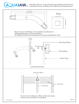
a. Install glass shelf, hand-held sliding bar, towel bar if applicable, soap/shampoo
dispensers if applicable, mirror if applicable, through-wall elbows to back walls through
pre-drilled holes.
b. Please check the installation diagrams below:
Through-wall Elbow Installation
Shelf Installation
Shampoo Dispenser Installation

8
★7. Glass Door Installation (Do this step after step 9)
Hand-held shower
Hand-shower head
sliding bar
Hand-held shower water
hose connection from the
elbow
Door Handle Installation
a. Put rollers on top of the doors into
the top rail first.
b. Then put the rollers on the bottom
into the bottom rail by pushing the
rollers downward to cut into the U
tracks.
c. Adjust the screws on the top rollers if
necessary.
d. Install the door handles.
e. Install the magnetic door seals to the
front edges of the doors.
f. Install the L door seals to the back
edges of the doors, making sure the
L pointing outward to the front the
glass panels.

9
Door roller in top track
(31 stands for glass)
Door roller in lower track
★
★★
★
8.
Unit Assembly
a. Connect the front frame to the channeled angles
on both sides (drawing on page 3)
b. Connect left back panel to the left side panel
from the back with ½” screws and set them in
place on the base.
c. Connect right back panel to the right side panel
from the back with ½” screws and set them in
place on the base.
d. Place front-frame-angles assembly onto the base.
You need two people to move the assembly. Push
the assembly to let the edges of the side panels
fit into the channels.
e.Put the function panel close to its designated
place and connect hot and cold water supplies,
water supplies to overhead shower, hand-held
shower, body jets.
f. Connect electrical wires from the electronic
control to LED lights, Fan, and speaker. All wires
have a tag at the ends for its function. Connect
power supply transformer to the electronic
control and plug the power to the wall outlet.
g. Place the roof of the unit on top of the shower
enclosure, aligning it with the walls, and fixing it
to the wall studs through the edge foldup.
h.Please watch this video: S-3460 Overall Assembly:
https://youtu.be/qHHco9dYRO0
Backwalls are attached to the stiles
of the Side Walls with ½” screws

10
★9. Unit installation
a. Connect and secure all water lines to the shower enclosure. Make sure all connections
are water tight! If your unit comes with a built-in radio, plug it into a 120V outlet.
b. Match up the electrical wire connectors (by pictures on the tags) for LED lights,
speaker, and fan. (The DC powers both lights If your unit has both dome and panel
LED lights.)
c. You may apply silicone sealant to the outer edge of the base.
d. Secure the unit to the wall using the 3” dry wall screws. Drill a pilot hole (1/8”) on the
top of the angle toward wall studs. You have to drill in a slanted angle. Drive the dry
wall screws through the holes. The screws MUST be screwed into a stud or a drywall
anchor.
★10. Caulking
Use silicon sealant to
seal all the seams or
joints from inside
the shower
.
/