Baldwin Boxall CPS Operating instructions
- Type
- Operating instructions

CALLCARE Installation Leaflet Revision 2.05
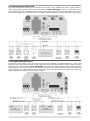
WIRING DETAILS
WHAT IS CALLCARE ?
CALLCARE is an Addressable Call System which
only requires two com mon connections to operate
(W e call this the Network). This m ak es it ideal f or
upgrading an older system using the existing wiring
and new installations are very straight forward.
Expansion is also sim ple as new units only require
a connection to the nearest or most convenient part
of the network.
The heart of the system can either be the CPSU
M AST E R P OW E R SU PP LY H UB or for smaller
system s, we recomm end the CLED32 D ISP LAY
CONTROLLER which is a combined LED Display
and Power Supply in a single unit. CALL POINTS
are located in the bedrooms, lounges and comm on
rooms where a call is to be generated. All call points
can generate two levels of call (standard patient call
& em ergency staff call) P EAR L EADS plug onto the
call points to provide a portable call button and
generate a standard call. In toilets and bathrooms
CEILING PULL SWITCHES are fitted over the toilet
and/or bath. They are connected directly back to a
call point to provide the reset. Locate Call Points
away from the bath/shower/sink or outside the
room. The LED DISPLAY UNITS show the number
of the call point(s) which are calling, together with
sounding an alarm. Any number of Display Units
may be connected to a system and they are
generally located around the building in corridors
and/or at nurses s tations depending on the
establishment. OVERDOOR LIGHTS are an
optional item and are generally located above the
door outside a room to indicate the call point inside.
These mimic the confidence LED on the call point
and are available with an integral sounder fitted.
Doors can be monitored with the use of the DOOR
MONITORING POINT connected to door contacts.
This unit is similar to the call point with a keyswitch
which can be used to isolate the unit when the door
is in use. The confidence LED lights green to
indicate the door is isolated. On very large systems
or system s with great cable loading, an additional
B OO S T ER PO W ER SU PP LY may be required.
T h i s is similar to the Power supply and houses an
additional battery. Radio tone pagers, auxiliary
sounders, strobe lights etc. m ay be connected to
the system via the Display unit, which has an output
for this purpose.
IMPORTANT
The Social Services and Health Authorities control
Nursing & Residential Hom es and the requirements
vary depending on the area. Please check that the
equipm ent you have specified and the location of
the equipm ent is acceptable before you start
installation.
GENERAL
Ceiling pull switches connect directly to a call
point which provides the reset facility. Any closing
contact will need a call point to trigger the system
and this becom es the reset point.
Standard Overdoor Lights require an additional
connection from the call point(s) they are to operate
with. (This could be one of the ‘spare’ cores in the 4
core cable)
Remote Reset is available on the CLED32 Display
Controller & CPSU by connecting a switch to the
reset pints. (This function is not normally allowed in
nursing & residential hom es)
WIRING GENERAL
Locate the power supply hub near the centre of the
building and run ‘spurs’ from this point via each call
point, overdoor light and display in each area. Avoid
running cables alongside fluorescent lighting, m ains
switchgear, lift machinery or high voltage cables.
W e do not recom mend cable ‘rings’ as this
increases cable loading and m ak es fault finding
more complicated. To calculate how m any ‘spurs’
you will require depends upon the am ount of
equipm ent you have on the network. Please read
the section on CABLE RESTRICTIONS for m ore
information.
CABLE
Do not use solid core cable as it is fragile and not
flexible. Four core stranded security alarm cable
(7/0,2) is ideal for all parts of the system wiring.
E XI ST IN G C AB L E
The CALLCARE system is ideal for use where the
existing cable may be used. Check the cables are
in good condition m echanically & Electrically.
1ST FIX
Call Points, Overdoor Lights & LED Displays require
1 Gang 25mm depth plastic backbox (Crabtree
9047 or similar) or m etal backbox for flush
mounting. The CLED32 Display Controller requires
a 3 Gang 30m m depth plastic backbox (MK K2153)
for surface m ounting or a 35mm depth m etal
backbox (VOLEX VX7301) for flush m ounting.
E QU IP M EN T L O CAT IO N
Mount Call Points above final bed head height to
stop damage to pear leads when beds are moved.
Avoid locating call points above radiators or any
heat source as this may af fect the front panel.
CLED99 Display & CLED32 Display Controller
should be m ounted in a suitable location to attract
attention. CPSU & CPSUB are supplied in surf ace
mounting boxes measuring W 230x180x85mm . You
should m ount these units in an accessible position.
After first fix, remove units from site and cover
mounting boxes with plank plates until 2n d fix.

CALLCARE Installation Leaflet Page 2
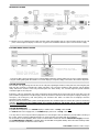
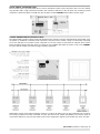
NEW INSTALLATIONS
Locate the CPSU or CLED32 Power supply near the centre of the building and run ‘spurs’ from this point via each call
point, overdoor light and display in each area. A typical new installation with two ‘spurs’ from the Power Supply.
EXISTING WIRING INSTALLATIONS
The CALLCARE system is ideal for use in older buildings where the existing cable may be used. A typical upgrade
using the existing wiring with the addition of an extra display & call points simply connected to the nearest call points.
SYSTEM OPERATION
The resident calls by pressing the call area on the call point, operating the button on the pear lead, removing the pear
lead from the call point or operating the ceiling pull switch. The call point confidence light operates and the display
unit(s) indicate the number of the call point and pulse the alarm slowly. The overdoor light will operate with the
confidence light on the call point.
Emergency calls are generated only at the call point by pressing both call and reset areas at the same time. The call
point confidence light flashes and the display shows the number as before but the alarm pulses rapidly indicating an
emergency call. Emergency calls take priority over standard calls which are held but not displayed until the
emergency call is cancelled.
When no calls are active on the system, the display flashes two confidence lights to indicate the system is functioning
c o rre ct l y. I mporta nt: T h e CALLCARE syste m uses soft to uch sw i tche s and s hould only be ope rate d w i th lig ht
pressure from a finger.
SYSTEM INFORMATION
A system must comprise of ; 1 x CLED32 Display Controller and 1 x CCRPJ Call Point OR
1 x CPSU Master Power Supply Hub, 1 x CLED99 Display Unit and 1 x CCRPJ Call Point.
You may wish to connect up the above equipment on a short length of wire to familiarise yourself with the working of
the system. Please read the Cabling Restrictions on page 12 before proceeding with the installation.
We recommend a backup battery in the event of a mains failure and this fits into the C PSU Pow e r Suppl y enclosure.
The C LED3 2 Displ ay C ontr olle r is supplied with a 9Volt Ni-MH rechargeable battery which fits into the battery holder
located on the printed circuit board of the CLED32.

CALLCARE Installation Leaflet Page 3
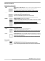
ORDERING INFORMATION
POWER SUPPLY CONTROLLERS
CPSU
Master Power Supply Unit with space for 12V 1.9/2.4 Ah Sealed Lead Acid
Battery.
Supports up to 80 CCRPJ Call Points and up to 99 Call Point Addresses.
Space for a backup battery 12Volt 1.9/2.4 Ah Sealed Lead Acid
Self contained surface mounting enclosure: W230mm x H 180mm x D95mm
No User Controls but should be located in an accessible position.
CPSUB
Booster Power Supply Unit with space for 12V 1.9/2.4 Ah Sealed Lead Acid
Battery.
For larger systems used in conjunction with CPSU.
Space for a backup battery 12Volt 1.9/2.4 Ah Sealed Lead Acid
Self contained surface mounting enclosure: W230mm x H 180mm x D95mm
No User Controls but should be located in an accessible position.
CLED32
Display Controller with Mute and Reset buttons.
Combined Power Supply and Display unit for systems of up to 32 Call Point
Addresses. Supplied with back up battery 8.4Volt 200mAh Ni-MH which fits into
battery holder on rear of unit.
Requires 3Gang backbox MK-K2136 (or similar) for surface mounting or
VOLEX VX7301 (or similar) 35mm depth metal backbox for flush mounting
Locate in a suitable position to attract staff attention and to allow operation of
controls.
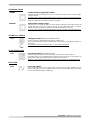
CALL POINTS / ADDRESSABLE CALLING DEVICES
CCRPJ
Call Point with two levels of call (Call & Emergency)
Required for each calling location on the system.
Requires 1Gang 25mm depth backbox (Plastic Round Cornered or metal flushing box)
Locate above final bed height to prevent damage to unit. Do not locate over heat
source.
CAODL
Room Controller with sounder, used with Ceiling Pull Switch & Slave Call / Resets
Combines the functions of an addressable call point and overdoor light in one unit.
Ideally suited to multiple disabled toilets when used in conjunction with CCS Ceiling Pull
Switch and CRP Slave Reset Point.
Requires 1Gang 25mm depth backbox (Plastic Round Cornered or metal flushing box)
Locate in a suitable position to attract staff attention outside the room or toilet.
DISPLAY UNITS
CLED99
LED Display Unit with integral sounder.
Any number may be used on a single system to identify the calling Call Points.
Requires 1Gang 25mm depth backbox (Plastic Round Cornered or metal flushing box)
Locate in a suitable position to attract staff attention with the audible sounder.

CALLCARE Installation Leaflet Page 4
OVERDOOR LIGHTS
CBODL
Simple Overdoor Light with Sounder.
Optional item located outside the room to indicate the status of the call point within.
Integral sounder.
Requires 1Gang 35mm depth backbox (Plastic Round Cornered or metal flushing box)
Locate in a suitable position to attract staff attention outside the room.
Requires additional connection back to the call point.
CAMODL
Addressable Overdoor Light.
Ideal for use as a ‘follow the light’ or ‘end of corridor’ indicator or to monitor several call
points with one single unit. Connects directly to the network and does not require
additional cabling. Jumper to enable unit to indicate emergency calls only.
Requires 1Gang 25mm depth backbox (Plastic Round Cornered or metal flushing box)
CELING PULL SWITCH
CCS
Ceiling Pull Switch with twin confidence LED’s
Used to generate call from bathroom, toilet or shower room.
This unit must be connected to an addressable calling device to provide the address on
the system.
Self contained surface mounting enclosure – No Backbox Required.
SLAVE RESET POINT
CRP
Slave Reset Point with confidence LED
Used in conjunction with the CCS and CAODL to provide the reset function or
used with CCRPJ as an additional slave reset point. This unit must be connected to an
addressable calling device to provide the address on the system.
Requires 1Gang 25mm depth backbox (Plastic Round Cornered or metal flushing box)
PEAR LEAD
CPL2
Pear Lead 2 Metre
Pear Leads plug into the front of the CCRPJ Call Point to provide a portable, easy to
operate call button. They are supplied in two and four metre lengths with a clip which
can be secured to bedding or clothing etc.

CALLCARE Installation Leaflet Page 5
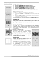
SYSTEM OPERATION Making a Standard Call
A Standard Call may be generated by any of the following:
• Pressing the Ca ll B u tt o n on the front of the Call Point
• Pressing the Pear Lead plugged into the front of the Call Point
• Un-plugging the Pear Lead from the front of the Call Point.
• Pulling the C e il in g P u ll S w it ch connected to the Call Point.
To Confirm a standard call has been generated, the Confidence LED w i l l li g h t .
Making an Emergency Call
An Emergency Call may be generated by any of the following:
• Pressing the C a ll B u tt o n & R eset Butt on simultaneously on the Call
Point.
• Pulling the C e il in g P u ll S w it c h connected to the Call Point if configured
by the installer to operate in this way.
To Confirm an emergency call has been generated, the Confidence LED flashes.
Resetting a Call
Make sure that the pear lead is not being activated and the call button is not
being pressed and press the Reset Bu tton on the call point.
The Confidence LED w i l l sw i tc h of f to c on f i rm t he ca l l i s re se t .
Showing a Standard Call
A Standard Call is shown on the LED displays with the calling point
numbers(s) scrolling automatically on the display. They may flash slowly or
remain steady on the display and the Sounder operates with a short
interrupted tone.
Showing an Emergency Call
An Emergency Call is shown on the LED displays
with the calling point numbers(s) scrolling
automatically on the display. They will flash rapidly
and the Sounder operates with a continuous pulsing
tone. Emergency calls take priority over standard
calls which are held in memory and only displayed
once all Emergency Calls are reset.
Overdoor Lights
Overdoor lights mimic the confidence LED on the
call points flashing slowly or steady for the standard
call and rapidly flashing for Emergency calls.
Remote Reset on the CLED32 Display Controller
It is possible to remotely reset any active call using
the Res et Butt on on the front of the Display
Controller. This will reset all active calls on the
system and may be disabled using by your installer.

CALLCARE Installation Leaflet Page 6
CCRPJ STANDARD CALL POINTS
Call Points are used to make calls and should be installed in every position where a call is to be reset or where
access to the emergency call is required. A standard call can be generated by the call button on the call point,
ceiling pull switch, pear lead and the removal of the pear lead, but emergency calls and call reset can only be
made at the call point. A maximum of 3 Ceiling pull switches (or any closing contact) may be connected to operate
one call point.
CALL POINT NUMBER SWITCHES
The 7 DIL switches set the number which is displayed when the call point is calling. Call Points may share the
same address, however calls can only be reset at the point from which they were generated. There is a full list of
the Call Point Address Switch Settings on page 14.
CCS CEILING PULL SWITCHES
A maximum of 3 CCS Ceiling Pull Switches may be connected to a single CCRPJ Call Point.

CALLCARE Installation Leaflet Page 7
CLED99 LED DISPLAY UNITS
Display units are used to alert staff and to indicate the calling room(s). They have a built in adjustable alarm which
has two distinctive sounds to indicate standard and emergency call. The call number is displayed with two large
numeric LED displays. There is practically no limit to the number of displays on a system provided the cabling
guidelines and restrictions are correctly followed. The display can store in memory and scroll up to 16 calls at any
time and emergency calls take priority over standard calls. The display can be configured to sound for emergency
calls only for use in Matrons office etc. The unit is fitted with an output, which can be used to drive radio tone
pagers or auxiliary equipment.
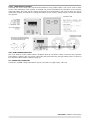
OUTPUT FOR AUX EQUIPMENT
The ‘T’ or Open Collector output on the display may be used to drive external equipment such as pagers etc. It is
possible to connect a relay to this terminal (See Diagram below) but an external 12volt DC supply will be required
as the +ve rail of the network is unsuitable. If the display is configured to only sound for emergency calls, the ‘T’
output will only respond to emergency calls. The output is active continuously while the display is sounding for
normal and/or emergency calls there is no change of state if more than one call is active.
The MAX loading on the ’T’ terminal is 100mA at 12volts DC and the minimum [ON] resistance is 100Ohms.
In the diagram above the LOAD could be a lamp, 12v Beeper or a relay coil if larger loads require switching. This
may be connected to the ‘R’ terminal of a call point on a separate system for zone indication. You will also need to
connect the network negative (-) on the two systems.
The Emergency Only Jumper also controls the output from the display and if this jumper is fitted then the open
collector output will only respond to emergency calls.
RADIO TONE PAGERS
Radio pagers are boxed with their own power supply, aerial and installation instructions. They are triggered from
the CALLCARE system via the ‘T’ terminal on the Display Unit (via a relay if necessary). If the display is configured
to only sound for emergency calls, the pager(s) will only respond to emergency calls. Please read the section on
the Display unit for more information.

CALLCARE Installation Leaflet Page 8
CLED32 DISPLAY CONTROLLER
The CLED32 is a combined addressable power supply & LED display unit, providing a flexible, cost effective
solution for small & medium sized call systems with a maximum of 32 Call Points. The unit is designed to be flush
or surface mounted into standard electrical backboxes. Always segregate low voltage & mains wiring.
MUTE AND RESET BUTTONS
The CLED32 Brings new features to the CALLCARE system with the addition of the RESET and MUTE buttons. The
mute button silences the audible alarm for a period of time. If a new call is generated, the audible alarm immediately
returns and the mute button must be pressed again to silence the new call audible alarm. There are four mute button
options set by the DIP switches. The reset button will reset all active calls on the system, if enabled by the DIP
switches. This button also serves as a self-test function.
INTEGRAL BACK UP BATTERY
The backup battery is continuously recharged from the mains supply and will typically support the system for 12 hours
in standby mode. The battery may be replaced using a Re-Chargeable Type 6F22 Ni-MH 8.4 Volt battery.
MAXIMUM SYSTEM SIZE USING CLED32
The CLED32 will support a maximum of 32 call points & 32 Overdoor lights or 22 Call Point with 22 Overdoor
lights and 1 LED display (The CLED99 LED Display will not respond to the mute function). The Call Points must
be addressed between Address 1 – Address 32 Any call point above address 32 will be ignored by the
CLED32.
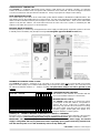
FUNCTION / FEATURE
DIP SW 1=UP 0=DOWN
1
2
3
4
5
6
7
8
Mute Button Disabled
1
1
-
-
-
-
-
-
Mute Timer = 2.5 minuets
0
0
-
-
-
-
-
-
Mute Timer = 7.5 minutes
1
0
-
-
-
-
-
-
Mute Timer = 15 minutes
0
1
-
-
-
-
-
-
Reset Button Disabled
-
-
1
1
-
-
-
-
Reset Button for Call Only
-
-
1
0
-
-
-
-
Reset Button Resets Calls & Emergency
-
-
0
0
-
-
-
-
Relay Operates for Calls & Emergency
-
-
-
-
0
-
-
-
Relay Operates for Emergency Only
-
-
-
-
1
-
-
-
Relay Relaxes when alarm muted
-
-
-
-
-
0
-
-
Relay Continues regardless of mute
-
-
-
-
-
1
-
-
Sound Using Call & Emergency Patterns
-
-
-
-
-
-
-
0
Sound Using continuous tone for all calls
-
-
-
-
-
-
-
1
JUMPER JP1 – CONNECT INTERNAL 9-18V SUPPLY TO RELAY ‘C’ TERMINAL
Fit jumper JP1 to connect the internal supply to the Relay ‘C’ terminal to provide voltage switching output from the
NO & NC terminals. Remove this jumper when using an external power source. Max current draw = 20mA.
IMPORTANT: The relay will only operate when the unit is powered from the mains supply. The internal
supply is unregulated and may vary between 9-18v DC depending upon system load. Driving external loads
from the internal power source will dramatically reduce backup battery life.
CONFIGURATION DIP SWITCHES
The features of the CLED32 are controlled with the
use of on-board DIP switches as shown below.
INTEGRAL RELAY OUTPUT
The CLED32 is fitted with an on-board relay, which
is configured via the DIP switches, and provides a
volt free, N.O or N.C contact set or voltage output.
The Relay only operates when the device is running
from mains power. This relay may be used to drive
sounders, pagers, strobe lights, auto diallers or to
integrate with BMS or SMS systems.

CALLCARE Installation Leaflet Page 9
CPSU MASTER POWER SUPPLY HUB
The Power Supply Hub provides the master signals and power for the network. The Power Supply requires a
mains supply connection and it houses the backup battery (12volt 1.9Ah/2.4Ah). There is a mains failure alarm
and unit status LED, the Yellow Mains LED is lit when mains supply is present, the DC LED indicates the 12v and
the red Micro LED flashes to indicate the unit is operating. Always segregate low voltage wiring from mains wiring.
CPSUB BOOSTER POWER SUPPLY
The Booster Power Supply is used to increase the amount of equipment and cable permitted on a system and
reproduces the signals from the Master Power Supply Hub. The Booster PSU requires a mains supply connection
and it houses the backup battery (12volt 1.9Ah/2.4Ah). A booster power supply may be required on existing wiring
installations because of the amount of cable loading, please read the cable restrictions section of this leaflet for
more information. The input to the Booster Power Supply MUST come directly from the output of the MPS unit.
Always segregate low voltage wiring from mains wiring.

CALLCARE Installation Leaflet Page 10
CBODL SIMPLE OVERDOOR LIGHT
The Overdoor Light is generally sited above a door to indicate the status of the call point in the room. The CBODL
only operates with a single call point and mimics the confidence indicator on the call point. For monitoring several
call points or where the light is over 5M from the call point use the CAMODL Addressable Overdoor Light.
CAMODL ADDRESSABLE OVERDOOR LIGHT
The Addressable Overdoor Light is physically identical to the standard overdoor light but being addressable, does
not require an additional connection to the call point. It may be used to monitor a range of consecutive call points
as an area indicator or to monitor several call points in one room. There are two banks of switches which set the
lowest & highest address that the unit is to respond to & is available with optional sounder, order code CAMODL.
An open collector output is provided to trigger auxiliary equipment.
Applications for this unit include monitoring exit doors or critical call points such as drug cupboards etc. Exit doors
are usually monitored and when activated, and the staff need to be alerted immediately. Set all door points to
consecutive addresses (say 90 to 99) and the unit can be configured to light and sound when any doors are open.

CALLCARE Installation Leaflet Page 11
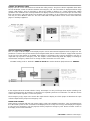
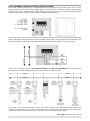
CAODL OVERDOOR LIGHT ROOM CONTROLLER WITH SOUNDER
The CAODL combines the functions of an addressable call point and overdoor light with sounder in an overdoor
light style unit. As can be seen from the diagram below, the circuit board is the same as a CCRPJ Call Point while
externally, the unit is a CBODL Overdoor Light. When used in conjunction with a Ceiling Pull Switch and Slave
Reset Point the unit becomes the ideal solution for multiple disabled toilets etc.
Any closing contact device can be connected to the CAODL to provide the call, reset and emergency signal to the
unit. The diagram on the left shows the connection method. The switches must be normally open momentary close
operation. Activation of the CALL and RESET buttons simultaneously will generate an emergency signal.
When used in conjunction with a CCS Ceiling Pull Switch and CRP Slave Reset Point the unit becomes the
ideal solution for multiple disabled toilets etc, as can be seen in the diagram below.
The CAODL can be used with mushroom “STOP” type buttons with key reset using both the normally open and
normally closed contact set in the button to generate the call and reset signals. Also, the unit can be connected to
a slave infra red receiver to allow emergency, call and reset from a wireless portable trigger.

CALLCARE Installation Leaflet Page 12
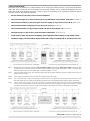
CABLE RESTRICTIONS
Locate the CPSU or CLED32 in a central location and run several spur cables from it in a ‘star’ format to minimise
cable runs. ‘Ring’ circuits are not recommended and should be avoided as they complicate installation. Run one
cable back to the PSU terminals from each corridor or wing etc, depending on the quantity of equipment. Please
read and adhere to the following restrictions:
• Do Not ‘Double up’ the cable cores used for the Network.
• The maximum single spur cable run must not exceed 100 Metres using 0.22mm2 CSA Cable. (See Note 1)
• The maximum number of Call Points and/or Overdoor Lights per spur must not exceed 30. (Notes 1 & 2)
• The maximum number of Displays per spur must not exceed 3. (See Note 1)
• The maximum number of Call points per CPSU = 80 and for the CLED32 = 32. (See Note 3)
• The total amount of cable on the system is limited to 1000metres. (See Note 4 & 5)
• A v oid running cables near fluorescent lighting, mains switchgear, lift machinery or high voltage cables
• The mai ns s upply con necti on MUST NOT be made with a plug socket & should be exclusive to the unit.
N ot e 1 M a xi m um l i m it f o r S ec u ri t y A la r m C ab l e w it h a C SA o f 0 . 22 m m2 i s 1 0 0M . Ma xi m um li mi t fo r 0.5mm2 f l e x i s 20 0 M . T hi s l im i t i s f or c ab le
v o lt d ro p p u r po s es a nd a ss u m es t ha t un i t s a re l o c at e d a t r eg u la r i n te r v al s a l on g t h e l en g th of t he c a b le . I f i n d o ub t – u s e l ar g er c a b le ,
h owe v e r t h e l a rg e st c a bl e y o u c a n u se wi th t he p lu g o n te r m in a ls s up p li e d i s 2 x 0 . 5m m 2
N ot e 2. ‘ Ca l l P o in t s ’ in c l ud e CCRPJ P o i nt s . The Ceiling pull switches with LED confidence indicators consume very little current and are not
usually restricted in number.
Note 3. If your system requires more than 80 Call Points, fit a CPSUB Booster power supply.
Note 4. This is calculated using security alarm cable with a conducting area of 7/0,2. Multi core cables & Twin & Earth cable have a lower
total cable loading limit. I f yo u n e ed t o e xc e ed t hi s v al u e y ou wi l l n e ed t o f i t a CPSUB B o os t er P owe r S u pp l y t o s p l it t he c ab l e l o ad i ng .
Note 5 If you are using multi-core cable, only use two cores within it’s length to make the network connection. Every time another network
+ve and -ve are connected within a multi-core cable, we are increasing the cable loading on the system. For example 10 call points
connected on a 20 metre run of multi-core cable on separate pairs is equivalent to 200 metres of cable loading on the network.

CALLCARE Installation Leaflet Page 13
2ND FIX
TESTING & COMMISSIONING - MASTER POWER SUPPLY HUB & DISPLAY CONTROLLER (See Page 9 &
Page 8)
• Connect the unit to the mains supply via a 3 amp spur unit DO NOT USE A PLUG & SOCKET.
• With no outputs connected, switch the power on & the unit will bleep or run through the display
segments*.
• After a pause, the Yellow and Green LED will be lit and the red LED or display dots* will be flashing.
• When running the unit from the battery, the Yellow LED will not be lit & the alarm will sound intermittently.
• Do not switch on by connecting the battery, the surge may blow the fuse.
• Switch the power supply off and connect one of the spurs to one of the output terminals ready to test the
first call point. * - CLED32 Display Controller Only.
CALL POINTS/DOOR POINTS (See Page 3)
Before we can test a call point, we will need to set the number switches. (See Page 14) As an example, we will set
this call point to address 1. (Set Switch 1 OFF and all others ON)
• Connect the first call point to the network +ve and -ve.
• Switch the Power Supply on and wait for the call point confidence LED will flash once.
• Press the call area on the call point and the confidence LED will flash about once a second.
• Press the reset area and the confidence LED will stop flashing.
DISPLAY UNITS (See Page 7)
• Switch the power supply off and connect the first display to the network +ve and -ve.
• Switch the Power Supply on and the display will perform a self test.
• When this is complete, two dots will flash slowly on the display to confirm the system is operating
correctly.
• You may configure any display to only respond to emergency calls by fitting a jumper (See Page 7)
STANDARD CALL TEST
• Press the call area on the call point and the confidence LED will flash about once a second.
• After a short delay, the display will flash ‘1’ and the alarm will sound every three seconds.
• Press the reset area and the confidence LED will stop flashing.
• The display alarm will stop sounding and the two confidence lights will flash slowly.
EMERGENCY CALL TEST
• Press the call and reset area on the call point at the same time and the confidence LED will flash rapidly.
• After a short delay, the display will flash ‘1’ and the alarm will sound twice a second.
• Press the reset area and the confidence LED will stop flashing.
• The display alarm will stop sounding and the two slow flashing dots will return.
OVERDOOR LIGHTS AND CEILING PULL SWITCHES (See Page 3 and Page 9)
• Connect and test the call point before connecting the overdoor lights and/or Ceiling pull switches.
• The Overdoor lights & Ceiling Pull Switch confidence LED will mimic the confidence LED on the call point.
• Test all ceiling pull switches connected to each call point.
BOOSTER POWER SUPPLY (See Page 9)
• Before connecting the Booster Power Supply input, connect & test the Master power supply circuit.
• Connect the master circuit to the Booster Power Supply input terminals.
• Connect the Booster Power Supply to the mains supply via a 3 amp spur unit.
• With no outputs connected, switch the power on and the unit will bleep for about four seconds.
• Providing the input is connected & the master circuit is running, the red LED will be pulsing once a
second.
• When running the unit from the battery, the Yellow LED will not be lit and the alarm will sound
continuously.
• Switch the power supply off and connect a spur to the output terminals ready to test the next call point.
ALWAYS CHECK ALL CALL POINT ADDRESSES ARE CORRECT BEFORE LEAVING SITE!
If you are in any doubt about the operation of a unit, please refer to the fault finding section on page 14.
ALL UNITS ARE FITTED WITH REVERSE POLARITY PROTECTION AND WILL BLOW THE FUSE OR
CAUSE THE POWER SUPPLY TO PERMANENTLY RESET IF CONNECTED INCORRECTLY!

CALLCARE Installation Leaflet Page 14
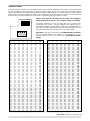
SWITCH SETTINGS
Each call point has a bank of seven switches which set the number displayed and recorded on the printer when
the unit is calling. Several call points can have the same number, but a call can only be reset at the call point
where it was initiated. The table below shows the available number settings. To set the number, turn the call point
upside down and set the switches as follows : ON is upwards (towards the word ‘ON’) & OFF is down (away from
the word ‘ON’) The call point below is set to address 1 (Switch 1 OFF and Switches 2-7 ON)
Address Switches
Address Switches
1
2
3
4
5
6
7
ADD
1
2
3
4
5
6
7
ADD
OFF
ON
ON
ON
ON
ON
ON
1
OFF
OFF
ON
ON
OFF
OFF
ON
51
ON
OFF
ON
ON
ON
ON
ON
2
ON
ON
OFF
ON
OFF
OFF
ON
52
OFF
OFF
ON
ON
ON
ON
ON
3
OFF
ON
OFF
ON
OFF
OFF
ON
53
ON
ON
OFF
ON
ON
ON
ON
4
ON
OFF
OFF
ON
OFF
OFF
ON
54
OFF
ON
OFF
ON
ON
ON
ON
5
OFF
OFF
OFF
ON
OFF
OFF
ON
55
ON
OFF
OFF
ON
ON
ON
ON
6
ON
ON
ON
OFF
OFF
OFF
ON
56
OFF
OFF
OFF
ON
ON
ON
ON
7
OFF
ON
ON
OFF
OFF
OFF
ON
57
ON
ON
ON
OFF
ON
ON
ON
8
ON
OFF
ON
OFF
OFF
OFF
ON
58
OFF
ON
ON
OFF
ON
ON
ON
9
OFF
OFF
ON
OFF
OFF
OFF
ON
59
ON
OFF
ON
OFF
ON
ON
ON
10
ON
ON
OFF
OFF
OFF
OFF
ON
60
OFF
OFF
ON
OFF
ON
ON
ON
11
OFF
ON
OFF
OFF
OFF
OFF
ON
61
ON
ON
OFF
OFF
ON
ON
ON
12
ON
OFF
OFF
OFF
OFF
OFF
ON
62
OFF
ON
OFF
OFF
ON
ON
ON
13
OFF
OFF
OFF
OFF
OFF
OFF
ON
63
ON
OFF
OFF
OFF
ON
ON
ON
14
ON
ON
ON
ON
ON
ON
OFF
64
OFF
OFF
OFF
OFF
ON
ON
ON
15
OFF
ON
ON
ON
ON
ON
OFF
65
ON
ON
ON
ON
OFF
ON
ON
16
ON
OFF
ON
ON
ON
ON
OFF
66
OFF
ON
ON
ON
OFF
ON
ON
17
OFF
OFF
ON
ON
ON
ON
OFF
67
ON
OFF
ON
ON
OFF
ON
ON
18
ON
ON
OFF
ON
ON
ON
OFF
68
OFF
OFF
ON
ON
OFF
ON
ON
19
OFF
ON
OFF
ON
ON
ON
OFF
69
ON
ON
OFF
ON
OFF
ON
ON
20
ON
OFF
OFF
ON
ON
ON
OFF
70
OFF
ON
OFF
ON
OFF
ON
ON
21
OFF
OFF
OFF
ON
ON
ON
OFF
71
ON
OFF
OFF
ON
OFF
ON
ON
22
ON
ON
ON
OFF
ON
ON
OFF
72
OFF
OFF
OFF
ON
OFF
ON
ON
23
OFF
ON
ON
OFF
ON
ON
OFF
73
ON
ON
ON
OFF
OFF
ON
ON
24
ON
OFF
ON
OFF
ON
ON
OFF
74
OFF
ON
ON
OFF
OFF
ON
ON
25
OFF
OFF
ON
OFF
ON
ON
OFF
75
ON
OFF
ON
OFF
OFF
ON
ON
26
ON
ON
OFF
OFF
ON
ON
OFF
76
OFF
OFF
ON
OFF
OFF
ON
ON
27
OFF
ON
OFF
OFF
ON
ON
OFF
77
ON
ON
OFF
OFF
OFF
ON
ON
28
ON
OFF
OFF
OFF
ON
ON
OFF
78
OFF
ON
OFF
OFF
OFF
ON
ON
29
OFF
OFF
OFF
OFF
ON
ON
OFF
79
ON
OFF
OFF
OFF
OFF
ON
ON
30
ON
ON
ON
ON
OFF
ON
OFF
80
OFF
OFF
OFF
OFF
OFF
ON
ON
31
OFF
ON
ON
ON
OFF
ON
OFF
81
ON
ON
ON
ON
ON
OFF
ON
32
ON
OFF
ON
ON
OFF
ON
OFF
82
OFF
ON
ON
ON
ON
OFF
ON
33
OFF
OFF
ON
ON
OFF
ON
OFF
83
ON
OFF
ON
ON
ON
OFF
ON
34
ON
ON
OFF
ON
OFF
ON
OFF
84
OFF
OFF
ON
ON
ON
OFF
ON
35
OFF
ON
OFF
ON
OFF
ON
OFF
85
ON
ON
OFF
ON
ON
OFF
ON
36
ON
OFF
OFF
ON
OFF
ON
OFF
86
OFF
ON
OFF
ON
ON
OFF
ON
37
OFF
OFF
OFF
ON
OFF
ON
OFF
87
ON
OFF
OFF
ON
ON
OFF
ON
38
ON
ON
ON
OFF
OFF
ON
OFF
88
OFF
OFF
OFF
ON
ON
OFF
ON
39
OFF
ON
ON
OFF
OFF
ON
OFF
89
ON
ON
ON
OFF
ON
OFF
ON
40
ON
OFF
ON
OFF
OFF
ON
OFF
90
OFF
ON
ON
OFF
ON
OFF
ON
41
OFF
OFF
ON
OFF
OFF
ON
OFF
91
ON
OFF
ON
OFF
ON
OFF
ON
42
ON
ON
OFF
OFF
OFF
ON
OFF
92
OFF
OFF
ON
OFF
ON
OFF
ON
43
OFF
ON
OFF
OFF
OFF
ON
OFF
93
ON
ON
OFF
OFF
ON
OFF
ON
44
ON
OFF
OFF
OFF
OFF
ON
OFF
94
OFF
ON
OFF
OFF
ON
OFF
ON
45
OFF
OFF
OFF
OFF
OFF
ON
OFF
95
ON
OFF
OFF
OFF
ON
OFF
ON
46
ON
ON
ON
ON
ON
OFF
OFF
96
OFF
OFF
OFF
OFF
ON
OFF
ON
47
OFF
ON
ON
ON
ON
OFF
OFF
97
ON
ON
ON
ON
OFF
OFF
ON
48
ON
OFF
ON
ON
ON
OFF
OFF
98
OFF
ON
ON
ON
OFF
OFF
ON
49
OFF
OFF
ON
ON
ON
OFF
OFF
99
ON
OFF
ON
ON
OFF
OFF
ON
50
Address settings shown in grey are not available when using the CLED32 Display Controller
1 2 3 4 5 6 7
ON DIP
Always check that all call points are set to the correct address
before leaving site as this is a very common reason for returning.
Call points addresses can be set while the unit is powered and
connected to the system. Only the settings in the following list are
valid address settings. Illegal address settings are indicated with the
Call Point confidence LED permanently lit or flashing rapidly. The Call
Point will not operate when the unit is set to an illegal setting.
Important: Call Points connected to the CLED32 Display Controller
will only operate between the address 1 and address 32. If you
required addresses 1-99, you must use the CPSU Master Power
Supply.

CALLCARE Installation Leaflet Page 15
FAULT FINDING
Please refer to the fault finding chart on page 16 for more information before reading network faults
NETWORK FAULTS - WHERE TO START?
The best approach to fault finding on the network is to start from the Master Power Supply Hub and
disconnect each spur in turn to establish where the fault is. This will instantly reduce the amount of units and
wiring which will require further investigation.
NETWORK FAULTS - VOLT DROP
Volt Drop faults are only likely to occur at installation, if the cable restrictions have not been adhered to or if
there are any bad or loose connections on the Network wiring. A cable short down a long run may appear to
be a volt drop fault but the units nearer to the short will have no supply and appear ‘dead’.
Typical volt drop symptoms are:
• LED displays fading or dim (especially when many segments are alight e.g. ‘88’)
• LED displays alarm tone fading or quiet.
• No operation from call point or call points resetting themselves automatically.
• Overdoor lights fading or dim (especially when more than one call active)
NETWORK FAULTS - SIGNAL CORRUPTION
Signal corruption occurs where the signals from the call points are prevented from getting to the displays.
This is achieved by having a slight short across the network - not enough to blow the fuse or cause the power
supply to reset. The most likely causes are damp, cable damage or non CALLCARE unit connected to the
network (e.g. Lamps Buzzers etc) This often occurs on existing wiring installations where not all of the old
parts of the system have been removed from the wiring.
Typical signal corruption symptoms are:
• LED displays confidence lights permanently lit. (See Page 7)
• LED displays confidence lights permanently off. (But volts present on Network)
• Numbers ‘frozen’ on displa y s .
• LED display alarm sounding continuously.
*It is possible for signal corruption to appear only locally so that only some displays are displaying the faults,
although this is very unlikely and will only occur on systems with large cable runs.
NETWORK FAULTS - CABLE LOADING
This is very similar to signal corruption but is unlikely to occur on systems with less than 50 call points unless
multi-core cable has been used extensively. The total cable loading prevents the signals from the call points
getting through to the displays. It can not be traced down to one spur but appears when all wiring is
connected. It is possible for damp cable to exhibit the symptoms of a cable loading fault but this can be
traced down to one spur.
Typical capacitance symptoms are:
• Call Point confidence LED flashing but does not sound on displays.
• Displays sound for calls then go back to dots, then show call number again intermittently.
• Faults similar to signal corruption but can not be found on one single cable ‘spur’.
• Number’s ‘frozen’ on displays.
• LED display alarm sounding continuously.
If you have more than one CPSUB Booster Power Supply on the system, check that the input to both
boosters comes directly from the Master circuit. (not from another booster) The cure is straightforward -
either remove some cable from the system or fit a CPSUB Booster Power Supply to supply one of the cable
spurs. The CPSUB Booster Power Supply may be fitted alongside the CPSU Master Power Supply.

CALLCARE Installation Leaflet Page 16
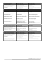
POWER SUPPLY FAULTS
SYMPTOM
REMEDY
Yellow LED off and/or Mains
Failure Alarm Sounding
No Mains Supply to unit
Check Mains Supply
Transformer Damaged (ie with a drill!)
Check holes in boxes!
CPSU Green LED off or Red LED not
flashing and/or Alarm sounding
continuously
On board 1 Amp fuse blown
Check Fuse
On board fuse holder loose around fuse
Check Fuse Holder
Short on Network wiring
Remove or eliminate Output connections
Flat or faulty battery
Check Battery
CALL POINT FAULTS
SYMPTOM
REMEDY
Confidence LED on continuously but not
indicating on Display
Illegal switch setting on call point
See Page 14
See NETWORK FAULTS page 14
See page 3
Confidence LED on continuously or
Call point will not reset.
Ceiling pull switch permanently shorted
Remove or eliminate ceiling pull switch
Pear Lead shorting
Remove or eliminate pear lead
Call Point Generates Emergency when
reset pressed
Condensation or damp on ceiling pull
switch
Check for water damage or stains on
plaster
Phantom calls from call point
Damaged cable to ceiling pull switch
Remove or eliminate ceiling pull switch
cable
No Operation from call point
No Supply to call point
Check Supply on Network
Network voltage below 7 volts
Measure network supply
See NETWORK FAULTS on page 14
Call point resets on its own
Intermittent supply to call point
Check connections
Intermittent connection on power supply
Check master power supply connections
No input to Booster Power Supply
Check master circuit
DISPLAY FAULTS
SYMPTOM
REMEDY
No confidence dots flashing on display or
display ‘locks up’ showing number or dots
permanently lit but not flashing
No Supply to display
Check supply
See NETWORK FAULTS on page 14
Display shows number but does not sound
Emergency calls only jumper fitted
Remove jumper (See Page 7)
No output from ‘T’ terminal.
Wiring error
See Page 7
Emergency calls only jumper fitted
Remove jumper (See Page 7)
BOOSTER SUPPLY FAULTS
SYMPTOM
REMEDY
CPSUB Yellow LED off and/or Mains
No Mains Supply on CPSUB
Check Mains Supply
Failure Alarm Sounding continuously
Transformer Damaged with a drill
Check holes in boxes!
CPSUB Green LED off or Red LED not
On board 1 Amp fuse blown
Check Fuse
flashing and/or Alarm sounding
continuously
On board fuse holder loose around fuse
Check Fuse Holder
Short on Network wiring
Remove or eliminate Output connections
Flat or faulty battery
Check Battery
CPSUB Red LED off or flashing slowly
(about one flash every two seconds)
No input signals from Master Circuit
Check master circuit (See Page 9)
-
 1
1
-
 2
2
-
 3
3
-
 4
4
-
 5
5
-
 6
6
-
 7
7
-
 8
8
-
 9
9
-
 10
10
-
 11
11
-
 12
12
-
 13
13
-
 14
14
-
 15
15
-
 16
16


Baldwin Boxall CPS Operating instructions
- Type
- Operating instructions
Ask a question and I''ll find the answer in the document
Finding information in a document is now easier with AI
Other documents
-
 Videotree Videospa VSPA19LCD-AE1W User manual
-
 EUfire NC951 Design & Installation Manual
-
ML Accessories OP9RCD User manual
-
ATC WEL3000 Installation, Operation & Maintenance Manual
-
Protec EVC40 Commissioning Manual
-
 ITLONG ITL-2MJ-A User manual
-
Eaton FX6000 addressable panel range Installation guide
-
-
-
Drive Medical Overdoor Exercise Pulley Owner's manual


