Page is loading ...

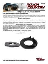
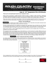
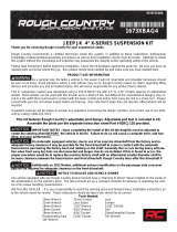
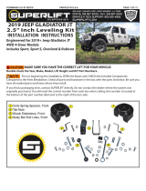
JEEP JK 2 1/2” SUSPENSION KIT
Thank you for choosing Rough Country for all your suspension needs.
Rough Country recommends a certified technician install this system. In addition to these instructions, professional
knowledge of disassemble/reassembly procedures as well as post installation checks must be known. Attempts to install
this system without this knowledge and expertise may jeopardize the integrity and/or operating safety of the vehicle.
Please read instructions before beginning installation. Check the kit hardware against the kit content list on this page and
the kit layout on the back page. Be sure you have all needed parts and know where they go. Also please review tools
needed list and make sure you have needed tools. As a general rule, the taller a vehicle is, the easier it will roll. Seat
belts and shoulder harnesses should be worn at all times. Avoid situations where a side rollover may occur.
Rough Country makes no claims regarding lifting devices and excludes any and all implied claims. We will not be re-
sponsible for any product that is altered.
This system was developed to provide a level stance to the Jeep after it is lifted. You will note that the front lift is 2.5”
and the rear lift is 2”. This is intentional and is the look most often requested. Also you will note that this lift does not
modify the front or rear track bar or its mounting points. This will result in what is generally considered an insignificant
shift in both the front and rear axle of approx 1/4 of an inch. Rough Country offers an optional rear track bar bracket to
address this. Please call your nearest Rough Country dealer to inquire.
This suspension system was developed using a 285/75R17” tire with factory wheels. If bigger/wider tire are used with the
factory wheels or factory offset wheels you must carefully check the clearance during turning between the tires and the
lower control arm and the front sway bar link before driving. If you have any questions concerning the design, function,
and correct use of our products contact us at 800-222-7023.
IMPORTANT NOTES : The draglink must be adjusted to the center steering wheel BEFORE the vehicle is driven.
Failure to do so will cause a computer error in the Jeep’s traction control system.
On Automatic equipped vehicles; due to use of an oversize driveshaft from the factory and inadequate
factory clearance it may be possible for the front driveshaft to come in to contact with the automatic transmis-
sion pan tearing the factory boot and rubbing on the shaft. Generally this occurs during heavy articulation when
front sway bar links are disconnected and longer shocks are installed. If this is found to occur, the proper pro-
cedure would be to replace the oversize factory shaft with an aftermarket smaller diameter shaft to increase
clearance between the transmission and front driveshaft. Rough Country does offer this driveshaft if needed.
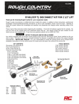
Kit Contents:
2— Front Coil Spring Spacers
2— Front Brake Line Brkts
2— Rear Coil Spring Spacers
2— Front Shock Extension
2— Rear Shock Extension
2—Rr Brake Line Ext Brkts
1--Poly Bag Containing:
2-.1/2” X 2 1/2” Bolts
2-1/2” lock washers
4-10mm x 80mm Bolts
4-10mm flat washers
2-Rear spacer retainers
2-12mm nuts
2-12mm x 65mm bolt
2-washers
2-5/16 x 3/4” bolt
2-5/16” nuts
4-5/16” washers
4-1/4” x 1” Bolts
4-1/4” Lock Nuts
8-1/4” Flat washers
92165600 REV1
Rear Spacer Retainers (2)
Rear Shock
Extender
Bracket (2)
Rear Coil Spacer (2)
Front Coil Spacer (2)
Front Shock Bracket(2)
Rear Brake Line Brkts
Front Brake Line Brkts

FRONT INSTALLATION INSTRUCTIONS
1. Chock the rear wheels and jack up the front of the vehicle and support the vehicle with jack stands so that the front
wheels are off the ground.
2. Using a 19mm deep well socket remove the front tires/wheels,
3. Using a 18mm socket and wrench remove the bottom sway bar bolts. Retain hardware for later use. See Photo 1
4. Using a 18mm socket and wrench remove the lower shock bolt. See Photo 2. Retain the lower hardware for reuse.
5. Using a 10MM socket, remove the brake line bracket from
the stock location.
6. Push down on the axle to allow room for the coils to be re-
moved. Remove coil springs, and factory spring isolator.
7. Install the new spacer over the factory bump stop with the
factory isolator as shown See Photo 3.
8. Reinstall the factory coil spring. Be sure to rotate the spring
until the pigtail hits the stop. See Photo 4.
9. Install the brake line extension bracket with the stock hard-
ware to the frame. Install the stock line to the bracket with the
supplied 1/4” x 1’ bolt, washers and nut. See Photo 5.
Photo 1 Photo 2
Photo 3
Photo 4
Tools Needed:
10mm Wrench
14mm Socket
16mm Wrench
16mm Socket
18mm Wrench
18mm Socket
19mm Deep Well Socket
Jack
Jack Stands
Size Grade 5 Grade 8
5/16” 15 ft/lbs 20 ft/lbs
3/8” 30 ft/lbs 35 ft/lbs
7/16” 45 ft/lbs 60 ft/lbs
1/2” 65 ft/lbs 90 ft/lbs
9/16” 95 ft/lbs 130 ft/lbs
5/8” 135 ft/lbs 175 ft/lbs
3/4” 185 ft/lbs 280 ft/lbs
Class 8.8 Class 10.9
6MM 5 ft/lbs 9 ft/lbs
8MM 18ft/lbs 23 ft/lbs
10MM 32ft/lbs 45ft/lbs
12MM 55ft/lbs 75ft/lbs
14MM 85ft/lbs 120ft/lbs
16MM 130ft/lbs 165ft/lbs
18MM 170ft/lbs 240ft/lbs
Torque Specs:
Photo 5

Photo 10
10. Install the shock bracket as shown in Photo 6 on the lower front mount at this time with supplied 12mm sleeves,
12mm x 65mm bolts and 5/16” x 3/4” bolts. See Photo 7. Tighten using a 18mm for the12mm bolt and a 1/2” for the
5/16”.Please note that there is a right and left side and the bracket will only install one way.
11. Install the stock shock with the factory bolt in the lower shock mount and tighten using a 18mm socket and wrench.
12. Reinstall the front tires/wheels and tighten to factory specifications.
13. Remove the jack stands and lower the vehicle to the ground. Install the sway bar links on the sway bar using
factory hardware using a 18mm wrench after the vehicle is on the ground. Do not install the sway bar link on
the sway bar until the sway bar is on the ground.
14. The draglink must be adjusted to center the steering wheel BEFORE the vehicle is driven. Failure to do so will
cause a computer error with the Jeep’s traction control system and will result in odd handling and poor performance.
Photo 6 Photo 7
REAR INSTALLATION INSTRUCTIONS
1. Chock front wheels and jack up the rear of the vehicle and support the vehicle with jack stands so that the rear
wheels are off the ground. Remove the rear tires/wheels, using a 19mm deep well socket.
2. Remove the upper shock bolt using a 16mm socket and wrench. Remove the lower shock bolt using a 18mm socket
and wrench and remove the factory shock. See Photo 7. Retain the lower shock hardware for reuse.
3. Using a 18mm socket and wrench remove the bottom sway bar bolts. Retain hardware for later use. See Photo 8.
5. Using a 10mm wrench remove the bolt holding the brake line to the frame. See Photo 9.
6. Attach the brake line bracket to the location on the frame where the factory bracket was attached. Tighten using a
10mm wrench and stock hardware. Secure the factory bracket to the bottom hole of the relocation bracket using a
7/16 wrench and the supplied .250-20 x 1” bolts, washers, and nuts. See Photo 10.
Photo 7 Photo 8
Photo 10
Photo 9

7. Push down on the axle to allow enough room for stock coil
spring to be removed. Remove the stock coil spring and isola-
tor.
8. Install the new coil spring spacer with supplied washer/nut
retainer and secure the assembly with supplied 1/2” x 2 1/2”
bolt & lock washers through the factory coil mount as shown
in Photo 12,13 & 14.
9. Install the factory coil spring isolator as shown. See Photo 15.
10. Install the top of the coil back onto the coil seat. When install-
ing the bottom of the coil into the seat rotate the coil until the
pigtail hits the spring stop. Lower vehicle slightly, watching
coils to assure they properly seat on top.
11. Reinstall the sway bar link using a 18mm socket and wrench
using the stock hardware. Install the brake line bracket re-
moved in step 5 using factory hardware.
12. Install the rear shock extender brackets with the supplied 10mm x 80mm bolts/washers as shown in Photo 16. Re-
install the shock in the lower mount with factory hardware using a 18mm wrench.
13. Reinstall the rear tires/wheels and tighten to factory specifications. Lower the vehicle to the ground.
Photo 12
Photo 14
Photo 13
Photo 15 Photo 16
POST INSTALLATION
1. Check all fasteners for proper torque. Check to ensure there is adequate clearance between all rotating, mobile,
fixed and heated members. Check steering for interference and proper working order. Test brake system.
2. Perform steering sweep. Cycle the steering from full turn to full turn to check for clearance. Failure to perform in-
spections may result in component failure.
3. The draglink must be adjusted to the center steering wheel BEFORE the vehicle is driven. Failure to do so will
cause a computer error with the Jeeps traction control system and result in odd handling and poor performance.
4. Using an certified alignment professional with experience in aligning lifted vehicles, get an alignment done to factory
specifications.
5. Readjust headlights to proper settings. MAINTENANCE INFORMATION
It is the ultimate buyers responsibility to have all bolts/nuts checked for tightness after the first 500 miles and then every
1000 miles. Wheel alignment steering system, suspension and driveline systems must be inspected
by a qualified professional mechanic at least every 3000 miles.
INSTALLING DEALER - it is your responsibility to install the warning decal and forward these installation instructions on
to the vehicle owner for review. These instructions should be kept in the vehicle for its service life.

Thank you for choosing Rough Country for your suspension needs.
Rough Country recommends a certified technician install this system. In addition to these instructions, professional
knowledge of disassemble/reassembly procedures as well as post installation checks must be known. Attempts to install
this system without this knowledge and expertise may jeopardize the integrity and/or operating safety of the vehicle.
Please read instructions before beginning installation. Be sure you have all needed parts and know where they go.
Please review tools needed list and make sure you have needed tools.
PRODUCT USE INFORMATION
If question exist we will be happy to answer any questions concerning the design, function, and correct use of our prod-
ucts by calling 1-800-222-7023.
This bracket is to allow the rear axle to be centered after installing the 2 1/2” kit from Rough
Country. Normally when the 2 1/2” kit is installed the rear axle pulls slightly to the passenger side ( approx.
1/4”). Installing this optional bracket will return the axle to center under the rear of the Jeep.
TOOLS NEEDED:
The following tools will be needed to complete this installation:
21MM Socket/Wrench
22MM Socket/Wrench
3/4” Socket/Wrench
INSTALLATION INSTRUCTIONS
1. Park the vehicle on a level surface and chock the front wheels.
2. Jack up the rear of the vehicle and place jack stands under the frame rails just forward of the rear lower control
arms. Lower the rear of the vehicle onto the jack stands.
3. Support the rear axle using a floor jack.
4. Remove the track rod from the frame mount using a 21mm wrench—driver side of vehicle. It may be necessary to
raise or lower to take the pressure off of the track rod bolt.
5. Place the bracket on the factory mount and install the supplied 3/8” x 1” Bolts , washers and Flange lock nuts as
shown in the factory holes. Do not tighten at this time. See Photo 1.
6. Using the track bar bracket as a template mark and drill a 13/32” hole in the top of the original track bar mount from
the top.
7. Install using the .375-16 x 1” bolt, washer through the drilled hole from the top and secure with flange nut using a
9/16” wrench and socket. See PHOTO 2.
92116700
Photo 1
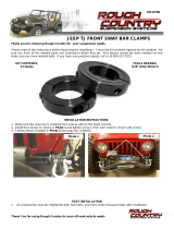
JEEP JK REAR TRACK ROD BRACKET
(FOR USE WITH 2 1/2” KIT)
Install crush sleeve and bracket on frame Install the 1/2” x 1 1/4” bolt
Photo 2

8. Insert the supplied sleeve, inside the factory track bar mount. Insert the supplied 14mm” x 80mm” bolt through the
bracket, factory mount, and sleeve secure using the washer and nut. Do fully tighten. See Photo 3.
9. Tighten all track rod bracket hardware.
10. Install the rear Rough Country Performance 2.2 shock in the factory location using the factory hardware. Tighten the
upper mount using a 16mm wrench and a 18mm wrench for the lower.
11. Reinstall the rear tires/wheels and tighten to factory specifications. Lower the vehicle to the ground.
12. After the vehicle is on the ground, install the stock track rod in the lower hole of the new track rod bracket with the
stock hardware. See Photo 4. It may be necessary to pull the axle over to the passenger side to align the hole in the
bracket with the track rod bushing.
The top hole is for 6” of lift, middle for 4” of lift and the bottom hole is for 2.5”-3.5” of lift.
The passenger side mount on the track bar will be installed in a later step.
13. Tighten all hardware using a 3/4”, 21mm & 22mm sockets/wrench.
14. Jack up the rear of the vehicle and remove the jack stands.
15. Lower vehicle to the ground.
MAINTENANCE INFORMATION
It is the ultimate buyers responsibility to have all bolts/nuts checked for tightness after the first 500 miles and then every
1000 miles. Wheel alignment steering system, suspension and driveline systems must be inspected by a qualified pro-
fessional mechanic at least every 3000 miles.
Thank you for purchasing a Rough Country Suspension Component.
Photo 3 Photo 4
Install the track bar in the new bracket
By purchasing any item sold by Rough Country, LLC, the buyer expressly warrants that he/she is in compliance with all
applicable Federal, State, and Local laws and regulations regarding the purchase, ownership, and
use of the item. It shall be the buyers responsibility to comply with all Federal, State and Local laws
governing the sales of any items listed, illustrated or sold. The buyer expressly agrees to indemnify
and hold harmless Rough Country, LLC for all claims resulting directly or indirectly from the purchase,
ownership, or use of the items.
/